Page is loading ...

ISTRUZIONI E AVVERTENZE PER L’INSTALLATORE
INSTRUCTIONS AND RECOMMENDATIONS FOR THE INSTALLER
ANWEISUNGEN UND HINWEISE FÜR DEN INSTALLATEUR
INSTRUCTIONS ET AVERTISSEMENTS POUR L’INSTALLATEUR
INSTRUCCIONES Y ADVERTENCIAS PARA EL INSTALADOR
INSTRUÇÕES E AVISOS PARA O INSTALADOR
Serie R20
Automazione per cancelli a baente
Swing gates automaons
Automasierung für Drehtore
Automasme pour portails à baant
Automasmos para cancelas baentes
Automações para portões de batente
Istruzioni originali
IS10 Rev.05 09/07/2018

3
EN
3
General safety precauons
Failure to respect the informaon given in this manual may cause personal injury or damage to the
device.
This installaon manual is intended for qualied personnel only.
ROGER TECHNOLOGY cannot be held responsible for any damage or injury due to improper use or any use other the intended usage indicated in
this manual.
Installaon, electrical connecons and adjustments must be performed by qualied personnel, in accordance with best pracces and in
compliance with applicable regulaons.
Read the instrucons carefully before installing the product. Bad installaon could be dangerous.
Before installing the product, make sure it is in perfect condion: if in doubt, do not use the equipment and contact qualied personnel only.
Do not install the product in explosive areas and atmospheres: the presence of inammable gas or fumes represents a serious safety hazard.
Before installing the motorisaon device, make all the necessary structural modicaons to create safety clearance and to guard or isolate all the
crushing, shearing, trapping and general hazardous areas.
Make sure the exisng structure is up to standard in terms of strength and stability.
ROGER TECHNOLOGY is not responsible for failure to observe Good Working Methods when building the frames to be motorised, or for any
deformaon during use.
The safety devices (photocells, safety edges, emergency stops, etc.) must be installed taking into account: applicable laws and direcves, Good
Working Methods, installaon premises, system operang logic and the forces developed by the motorised door or gate.
The safety devices must protect against crushing, cung, trapping and general danger areas of the motorised door or gate.
The European standards EN 12453 and EN 12455 dene the minimum safety requirements for the operaon of automac doors and gates. In
parcular, these standards require the use of force liming and safety devices (sensing ground plates, photocell barriers, operator detecon
funcon etc.) intended to detect persons or objects in the operang area and prevent collisions in all circumstances.
Where the safety of the installaon is based on an impact force liming system, it is necessary to verify that the characteriscs and performance
of the automaon system are compliant with the requisites of applicable standards and legislaon.
The installer is required to measure impact forces and programme the control unit with appropriate speed and torque values to ensure that the
door or gate remains within the limits dened by the standards EN 12453 and EN 12455.
ROGER TECHNOLOGY declines all responsibility if component parts not compable with safe and correct operaon are ed.
Display the signs required by law to idenfy hazardous areas.
Each installaon must bear a visible indicaon of the data idenfying the motorised door or gate.
An omnipolar disconnecon switch with a contact opening distance of at least 3mm must be ed on the mains supply.
Make sure that upline from the mains power supply there is a residual current circuit breaker that trips at no more than 0.03A and overcurrent
cutout upstream of the electrical system in accordance with best pracces and in compliance with applicable regulaons.
When requested, connect the automaon to an eecve earthing system that complies with current safety standards.
During installaon, maintenance and repair operaons, cut o the power supply before opening the cover to access the electrical parts.
The electronic parts must be handled using earthed anstac conducve arms.
Only use original spare parts for repairing or replacing products.
The installer must supply all informaon concerning the automac, manual and emergency operaon of the motorised door or gate, and must
provide the user with the operang instrucons.
The packaging materials (plasc, polystyrene, etc.) should not be discarded in the environment or le within reach of children, as they are a
potenal source of danger.
Dispose of and recycle the packing components in accordance with the standards in force.
These instrucon must be kept and forwarded to all possible future user of the system.
Declaraon of Conformity
I the undersigned, as acng legal representave of the manufacturer:
Roger Technology - Via Bocelli 8, 31021 Bonisiolo di Mogliano V.to (TV)
hereby DECLARE that the appliance described hereaer:
Descripon: Swing gate automaon
Model: serie R20
Is conformant with the legal requisites of the following direcves:
• Direcve 2004/108/EC (EMC Direcve) and subsequent amendments;
• Direcve 2006/95/EC (Low Voltage Direcve) and subsequent amendments;
and that all the standards and/or technical requirements indicated as follows have been applied:
EN 61000-6-3
EN 61000-6-2
EN 60335-1
EN 60335-2-103
Last two gures of year in which marking was applied | 03.
Place: Mogliano V.to Date: 02-01-2003 Signature

8
DESCRIZIONE DESCRIPTION BESCHREIBUNG DESCRIPTION DESCRIPCIÓN DESCRIÇÃO
1 Automasmo R20 Automasm R20 Automasierung R20 Automasme R20 Automasmo R20 Automasmo R20
2 Centrale di comando Control panel Steuerung Centrale de commande Central de mando Central de comando
3 Seleore a chiave Key selector Schlüsseltaster Sélecteur à clé Selector de llave Selector de chave
4 Lampeggiante Flashing light Blinkleuchte Clignotant Luz intermitente Lampejante
5 Antenna Antenna Antenne Antenne Antena Antena
6 Fotocellula esterna External photocell Externe Lichtschranke
Cellule photoélectrique
externe
Barrera fotoeléctrica
exterior
Sensor fotoelétrico
externo
7 Fotocellula interna Internal photocell Interne Lichtschranke
Cellule photoélectrique
interne
Barrera fotoeléctrica
interior
Sensor fotoelétrico
exterior
8
Fermo meccanico in
apertura
Gate open mechanical
stop
Mechanische Feststell-
vorrichtung beim Önen
Butée mécanique en ou-
verture
Tope mecánico de aper-
tura
Retentor mecânico em
abertura
R20/300
R20/302
R20/3115
R20/300
R20/302
R20/3115
R20/500
R20/502
R20/500
R20/502
165 mm120 mm
320 / 520 mm
858.5 mm / 1088.5 mm
= 320 mm
= 520 mm
= 858.5 mm
= 1088.5 mm
1 IMPIANTO TIPO SERIE R20 • STANDARD INSTALLATION R20 RANGE • ANLAGETYP SERIE R20 • INSTALLATION
TYPE SÉRIE R20 • INSTALACIÓN TIPO SERIE R20 • SISTEMA DO TIPO SÉRIE R20
2 DIMENSIONI • DIMENSIONS • AUSSENMASSE • DIMENSIONS • DIMENSIONES • DIMENSÕES

9
R20/300
Motoriduore eleromeccanico per cancelli a baente no a 400 kg, larghezza anta no a 2,5 m - CORTO - VELOCE • Electromechanical gear motor for swing
gates weighing up to 400 kg, up to 2.5 m wide wing - SHORT - FAST • Elektromechanischer Getriebemotor für Drehtore bis zu 400 kg, Flügelbreite bis zu 2,5 m
- KURZ - SCHNELL • Motoréducteur électromécanique pour portails à baant jusqu’à 400 kg, largeur vantail jusqu’à 2,5 m - COURT - RAPIDE • Motorreductor elec-
tromecánico para cancelas baentes de 400 kg de peso máx., 2,5 m de anchura máx. - CORTO - RÁPIDO • Motor redutor eletromecânico para portões de batente
até 400 kg, largura da pornhola até 2,5 m - CURTO - RÁPIDO.
R20/302
Motoriduore eleromeccanico per cancelli a baente no a 400 kg, larghezza anta no a 3,5 m - CORTO - LENTO • Electromechanical gear motor for swing gates
weighing up to 400 kg, up to 3.5 m wide wing - SHORT - SLOW • Elektromechanischer Getriebemotor für Drehtore bis zu 400 kg, Flügelbreite bis zu 3,5 m - KURZ -
LANGSAM • Motoréducteur électromécanique pour portails à baant jusqu’à 400 kg, largeur vantail jusqu’à 3,5 m - COURT - LENT • Motorreductor electromecánico
para cancelas baentes de 400 kg de peso máx., 3,5 m de anchura máx. - CORTO - LENTO • Motor redutor eletromecânico para portões de batente até 400 kg,
largura da pornhola até 3,5 m - CURTO - LENTO.
R20/500
Motoriduore eleromeccanico per cancelli a baente no a 400 kg, larghezza anta no a 3,5 m - LUNGO - VELOCE • Electromechanical gear motor for swing ga-
tes weighing up to 400 kg, up to 3.5 m wide wing - LONG - FAST • Elektromechanischer Getriebemotor für Drehtore bis zu 400 kg, Flügelbreite bis zu 3,5 m - LANG -
SCHNELL • Motoréducteur électromécanique pour portails à battant jusqu’à 400 kg, largeur vantail jusqu’à 3,5 m - LONG - RAPIDE • Motorreductor electromecánico
para cancelas batientes de 400 kg de peso máx., 3,5 m de anchura máx. - LARGO - RÁPIDO • Motor redutor eletromecânico para portões de batente até 400 kg,
largura da portinhola até 3,5 m - LONGO - RÁPIDO.
R20/502
Motoriduore eleromeccanico per cancelli a baente no a 400 kg, larghezza anta no a 5 m - LUNGO - LENTO • Electromechanical gear motor for swing gates
weighing up to 400 kg, up to 5 m wide wing - LONG - SLOW • Elektromechanischer Getriebemotor für Drehtore bis zu 400 kg, Flügelbreite bis zu 5 m - LANG -
LANGSAM • Motoréducteur électromécanique pour portails à battant jusqu’à 400 kg, largeur vantail jusqu’à 5 m - LONG - LENT • Motorreductor electromecánico
para cancelas batientes de 400 kg de peso máx., 5 m de anchura máx. - LARGO - LENTO • Motor redutor eletromecânico para portões de batente até 400 kg, largura
da portinhola até 5 m - LONGO - LENTO.
R20/3115
Motoriduore eleromeccanico per cancelli a baente no a 400 kg, larghezza anta no a 2,5 m - CORTO - VELOCE, alimentazione 115 Vac • Electromechanical
gear motor for swing gates weighing up to 400 kg, up to 2.5 m wide wing - SHORT - FAST, 115 VAC power supply • Elektromechanischer Getriebemotor für Drehtore
bis zu 400 kg, Flügelbreite bis zu 2,5 m - KURZ - SCHNELL, Stromversorgung 115 V AC • Motoréducteur électromécanique pour portails à battant jusqu’à 400 kg,
largeur vantail jusqu’à 2,5 m - COURT - RAPIDE, alimentation 115 Vac • Motorreductor electromecánico para cancelas batientes de 400 kg de peso máx., 2,5 m
de anchura máx. - CORTO - RÁPIDO, alimentación 115 Vca • Motor redutor eletromecânico para portões de batente até 400 kg, largura da portinhola até 2,5 m -
CURTO - RÁPIDO, alimentação 115 Vac.
R20/300 R20/302 R20/500 R20/502 R20/3115
ALIMENTAZIONE MOTORE BRUSHLESS • BRUSHLESS MOTOR POWER
SUPPLY • EINSPEISUNG BRUSHLESS MOTOR • ALIMENTATION MOTEUR
BRUSHLESS • ALIMENTACION MOTOR BRUSHLESS • ALIMENTAÇÃO MO-
TOR BRUSHLESS
V 230 Vac 50 Hz 230 Vac 50 Hz 230 Vac 50 Hz 230 Vac 50 Hz 230 Vac 50 Hz
POTENZA NONIMALE • RATED POWER • NENNLEISTUNG
PUISSANCE NOMINALE • POTENCIA NOMINAL • POTÊNCIA NOMINAL
W 200 215 200 215 200
CORRENTE • CURRENT • STROM • COURANT • CORRIENTE • CORRENTE
A 1,1 1,2 1,1 1,2 1,1
INTERMITTENZA • JOGGING • AUSSETZENDER BETRIEB • INTERMITTENCE
• INTERMITENCIA • INTERMITÊNCIA
% 40 40 40 40 40
TERMO PROTEZIONE MOTORE • MOTOR OVERLOAD CUTOUT
• ÜBERHITZUNGSSCHUTZ MOTOR • THERMOPROTECTION MOTEUR
• TERMOPROTECCION DEL MOTOR • PROTECÇÃO TÉRMICA DO MOTOR
°C 140 140 140 140 140
TEMPERATURA DI ESERCIZIO • WORKING TEMPERATURE• BETRIEBSTEMPERA-
TUR • TEMPERATURE DE SERVICE • TEMPERATURA DE FUNCIONAMIENTO
• TEMPERATURA DE FUNCIONAMENTO
°C
-20°C +55°C
GRADO DI PROTEZIONE • PROTECTION RATING • SCHUTZGRAD •
DEGRE DE PROTECTION • GRADO DE PROTECCION • GRAU DE PROTEC-
ÇÃO
IP 43 43 43 43 43
PESO OPERATORE • OPERATOR WEIGHT • ANTRIEBSGEWICHT •
POIDS OPERATEUR • PESO DEL OPERADOR • PESO DO OPERADOR
kg 7,2 7,2 7,8 7,8 7,2
TEMPO APERTURA PER 90° • 90° OPENING TIME • ÖFFNUNGSZEIT FÜR 90° •
TEMPS OUVERTURE POUR 90° • TIEMPO PARA APERTURA DE 90° • TEMPO DE
ABERTURA PARA 90°
s 19“ 28“ 27“ 42“ 19“
VELOCITA‘ • WORKING SPEED • GESCHWINDIGKEIT DER TORBEWEGUNG
• VITESSE DE MANOEUVRE • VELOCIDAD DE MANIOBRA • VELOCIDADE
DE MANOBRA
cm/s 1,66 1,06 1,66 1,06 1,66
CONDENSATORE • CAPACITOR • KONDENSATOR • CONDENSATEUR •
CONDENSADOR • CONDENSADOR
µf 15 6,3 15 6,3 30
SPINTA • TRUST • SCHUB • POUSSEE • EMPUJE • IMPULSO
N 2500 2800 2500 2800 1800
CORSA • TRAVEL • HUB • COURSE • CARRERA • CURSO
mm 320 320 520 520 320
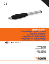
600
400
200
0
Kg
m
R20/300
R20/3115
1 2 3 4 5
600
400
200
0
Kg
m
R20/302
1 2 3 4 5
600
400
200
0
Kg
m
R20/500
1 2 3 4 5
600
400
200
0
Kg
m
R20/502
1 2 3 4 5
3 MODELLI E CARATTERISTICHE • MODELS AND SPECIFICATIONS • MODELLE UND EIGENSCHAFTEN
MODÈLES ET CARACTÉRISTIQUES • MODELOS Y CARACTERÍSTICAS • MODELOS E CARACTERÍSTICAS
4 DATI TECNICI • TECHICAL DATA • TECHNISCHE DATEN • DONNEES TECHNIQUES • DATOS TECNICOS •
CARACTERÍSTICAS TÉCNICAS
5 DIAGRAMMA DI UTILIZZO • WORKING DIAGRAM • VERWENDUNGSDIAGRAMM • DIAGRAMME
D’UTILISATION • DIAGRAMA DE UTILIZACION • DIAGRAMA DE UTILIZAÇÃO

10
IT
VERIFICHE PRELIMINARI PRIMA DELL’INSTALLAZIONE
Vericare che la struura del cancello sia robusta, che i cardini siano ben
ingrassa e che il movimento sia uido e regolare per tua la sua corsa
e senza ari.
Prevedere sempre una bauta meccanica di arresto in apertura e chiusura ben
ssata al suolo, dotata di un elemento elasco (esempio: gomma) che ausca
l’arrivo in bauta dell’anta.
In funzione al modello da installare, agli spazi e agli ingombri presen in sito e
in funzione all‘angolo di apertura desiderato, posizionare la staa posteriore sul
pilastro e vericare le misure di installazione indicate in tabella.
Le misure [A] e [B] devono essere sempre compabili con la corsa ule del pisto-
ne. Se la somma di [A]+[B] è maggiore della corsa massima, si deve accorciare la
staa posteriore, riducendo di conseguenza la misura [B]
NOTA: La punta del pistone deve convergere verso l‘anta.
EN
PRELIMINARY CHECKS
Check that the structure of the gate is sturdy and in good condion, that
the hinges are well greased and that the gate moves throughout its enre
travel smoothly without impediment or fricon.
Always install mechanical stops in the gate open and gate closed posions, ancho-
red securely to the ground and with elasc damper elements (e.g. rubber buer)
to aenuate the impact of the gate leaf against the stop.
Depending on the model installed, on the available space and any obstacles exis-
ng in the installaon site, and on the required angle of aperture, install the rear
bracket on the pillar and the check that the installaon measurements indicated
in the table are correct.
The measurements [A] and [B] must always be compable with the maximum
eecve travel of the piston. If the sum of the values [A]+[B] is greater than the
maximum travel, shorten the rear bracket to reduce measurement [B]
N.B: The end of the piston rod must meet the gate leaf.
DE
EINLEITENDE KONTROLLEN
Sicherstellen, dass die Struktur des Tors robust ist, die Angeln gut ein-
gefeet sind und die Bewegung über den gesamten Torlauf üssig und
regelmäßig, ohne Reibungen erfolgt.
Stets einen mechanischen Anschlag in Önung und Schließung vorsehen, der fest
am Boden verankert ist und über ein elassches Element (z.B.: Gummi) verfügt,
das den Anschlag des Torügels dämp.
Je nach zu installierendem Modell, Raum und Platzbedarf vor Ort sowie ge-
wünschtem Önungswinkel, den hinteren Bügel auf dem Pfeiler posionieren
und die in der Tabelle angegebenen Installaonsmaße überprüfen.
Die Maße [A] und [B] müssen immer mit dem Arbeitshub des Kolbens kompabel
sein. Wenn die Summe von [A]+[B] größer ist als der Maximalhub, muss man den
hinteren Bügel verkürzen und demzufolge das Maß [B] reduzieren
HINWEIS: Die Spitze des Kolbens muss zum Flügel gerichtet sein.
FR
CONTRÔLES PRÉLIMINAIRES
Vérier que la structure du portail soit robuste, que les gonds soient bien
graissés et que le mouvement soit uide et régulier sur toute la course et
sans froements.
Toujours prévoir une butée mécanique d‘arrêt en ouverture et fermeture bien
xée au sol, dotée d‘un élément élasque (exemple : caoutchouc) qui amorsse
l‘arrivée en butée du vantail.
En foncon du modèle à installer, des espaces et des encombrements présents
sur place et en foncon de l‘angle d‘ouverture souhaité, placer l‘étrier arrière sur
le pilier et vérier les cotes d‘installaon indiquées dans le tableau.
Les cotes [A] et [B] doivent toujours être compables avec la course ule du pis-
ton. Si la somme [A]+[B] est supérieure à la course maximale, raccourcir l‘étrier
arrière, en réduisant de conséquence la cote [B]
REMARQUE : La pointe du piston doit converger vers le vantail.
ES
COMPROBACIONES PRELIMINARES
Compruebe que la estructura de la cancela sea sólida, que los goznes es-
tén bien engrasados y que el movimiento sea uido y regular en toda su
carrera y no presente roces.
Monte siempre un tope mecánico para la apertura y el cierre bien jada al
suelo,dotada de un elemento elásco (ejemplo: goma) que amorgüe la llegada
de la hoja al cerrarse.
En función del modelo que se ha de instalar, del espacio y las dimensiones que
se encuentran in situ y en función del ángulo de apertura deseado, coloque el
estribo trasero sobre el pilar y consulte las medidas de instalación que guran
en la tabla.
Las medidas [A] y [B] siempre han de ser compables con la carrera úl del pistón.
Si la suma de [A]+[B] es superior a la carrera máxima, se deberá acortar el estribo
trasero, reduciendo por tanto la medida [B]
NOTA: La punta del pistón ha de converger hacia la hoja.
PT
CONTROLOS PRELIMINARES
Verique se a estrutura do portão é resistente, se as dobradiças estão
adequadamente lubricadas e se o movimento é uido e regular durante todo o
seu curso sem atritos.
Sempre preveja um batente mecânico de paragem em abertura e fecho bem
xo ao solo, fornecido de um elemento elásco (por exemplo,: borracha) que
amorteça a chegada em bada da pornhola.
Em função ao modelo a ser instalado, aos espaços e às dimensões presentes no
local e, dependendo do ângulo de abertura desejado, coloque o suporte traseiro
no pilar e verique as medidas de instalação indicadas na tabela.
As medidas [A] e [B] deverão sempre ser compaveis com o curso úl do pistão.
Se a soma de [A] + [B] for maior do que o curso máximo, é necessário encurtar o
suporte posterior, reduzindo assim a medida [B]
NOTA: A ponta do pistão tem que convergir no sendo da pornhola.
R20/300 - R20/302 - R20/3115
(Corsa massima • Max run = 320 mm)
A B C (max) D (max) E α°
130 130 90 730 90 90°
80 170 90 730 90 90°
80 210 90 730 90 90°
100 200 90 730 90 90°
120 140 90 730 90 100°
130 150 90 730 90 105°
150 100 90 730 90 120°
R20/500 - R20/502
(Corsa massima • Max run = 520 mm)
A B C (max) D (max) E α°
100 210 190 950 123 90°
150 210 190 950 123 90°
150 300 190 950 123 90°
250 180 190 950 123 110°
220 200 190 950 123 110°
180 130 190 950 123 120°
210 180 190 950 123 120°
C
B
D
A
E
6 VERIFICHE PRELIMINARI • PRELIMINARY CHECKS • EINLEITENDE KONTROLLEN • CONTRÔLES
PRÉLIMINAIRES • COMPROBACIONES PRELIMINARES • CONTROLOS PRELIMINARES

11
IT
FISSAGGIO STAFFE
1. Fissare la staa posteriore in bolla come da misure di installazione indicate al
paragrafo 6.
• Su pilastri in muratura ulizzare le stae predisposte per il po di materiale
con tasselli e vi adeguate.
• Su pilastri in ferro saldare la staa.
2. Con cancello completamente chiuso posizionare la staa anteriore, rispeando
le misure [D] e [E] e ssarla in bolla all’anta del cancello, come indicato in gura.
EN
FASTENING BRACKETS
1. Fasten the rear bracket in a perfectly level posion and in accordance with the
installaon measurements indicated in paragraph 6.
• For masonry/cement pillars, use the specic masonry brackets with suitable
anchor bolts and screws.
• With steel pillars, weld the bracket in place.
2. With the gate completely closed, t the front bracket to obtain the installaon
measurements [D] and [E], and fasten in a perfectly level posion to the gate
leaf as shown in the gure.
DE
BEFESTIGUNG DER BÜGEL
1. Den hinteren Bügel nivelliert nach den im Abschni 6 angegebenen Installa-
onsmaßen befesgen.
• Bei gemauerten Pfeilern die für dieses Material vorgesehenen Bügel mit
geeigneten Dübeln und Schrauben verwenden.
• Bei Eisenpfeilern den Bügel anschweißen.
2. Bei vollständig geschlossenem Tor den vorderen Bügel unter Einhaltung der
Maße [D] und [E] anbringen und nivelliert am Torügel befesgen, wie in der
Abbildung gezeigt.
FR
FIXATION DES ÉTRIERS
1. Fixer l’étrier arrière à niveau conformément aux cotes d’installaon indiquées
au paragraphe 6.
• Sur les piliers en maçonnerie, uliser les étriers prédisposés pour le type de
matériau avec chevilles et vis appropriées.
• Sur les piliers en fer, souder l’étrier.
2. Avec le portail enèrement fermé, placer l’étrier avant, en respectant les cotes
[D] et [E] et la xer à niveau avec le vantail du portail, comme indiqué dans la
gure.
ES
FIJACIÓN DE LOS ESTRIBOS
1. Fije el estribo trasero a plomo según las medidas de instalación indicadas en
el apartado 6.
• En pilares de hormigón ulice los estribos preinstalados para el po de ma-
terial con tacos y tornillos adecuados.
• Suelde el estribo en los pilares de hierro.
2. Con la cancela cerrada del todo coloque el estribo delantero, respetando las me-
didas [D] y [E] y jelo a plomo a la hoja de la cancela como se indica en la gura.
PT
FIXAÇÃO DOS SUPORTES
1. Fixe o suporte traseiro com um nível de bolha conforme as medidas de insta-
lação indicadas no parágrafo 6.
• Em pilares de alvenaria use os suportes adequados para o po de material
com buchas e parafusos apropriados.
• Em pilares de ferro solde o suporte.
2. Com o portão completamente fechado posicione o suporte dianteiro, respei-
tando as medidas [D] e [E] e xe-o com um nível de bolha à pornhola do
portão, conforme mostrado na gura.
60 mm
60 mm
7 FISSAGGIO STAFFE • BRACKETS FASTENING • BEFESTIGUNG DER BÜGEL • FIXATION DES ÉTRIERS •
FIJACIÓN DE LOS ESTRIBOS • FIXAÇÃO DOS SUPORTES

12
IT
INSTALLAZIONE
• Il pistone R20 può essere installato indierentemente a destra o a sinistra.
• Posizionare il pistone sulla staa posteriore e su quella anteriore lubricando
i pun di rotazione.
• Prima di ssare denivamente il pistone alle stae, procedere alla regolazione
dei micro interruori di STOP, come indicato al capitolo 10.
• Muovendo manualmente il cancello vericare che tua la corsa sia regolare e
senza ari.
• Fissare il pistone.
EN
INSTALLATION
• The R20 piston may be installed on the right or le hand side.
• Place the piston on the rear bracket and on the front bracket and lubricate the
pivot points.
• Before permanently fastening the piston to the brackets, adjust the stop micro-
switches as described in Chapter 10.
• Move the gate manually and check that it moves smoothly throughout its
enre travel without impediment or fricon.
• Fasten the piston.
DE
INSTALLATION
• Der Kolben R20 kann unterschiedslos rechts oder links installiert werden.
• Den Kolben am hinteren Bügel und am vorderen Bügel posionieren und die
Rotaonspunkte schmieren.
• Vor dem endgülgen Befesgen des Kolbens an den Bügeln die Endanschlag-
Mikroschalter einstellen wie in Kapitel 10 angegeben.
• Das Tor von Hand bewegen und prüfen, dass sein Lauf regelmäßig und
reibungslos erfolgt.
• Den Kolben befesgen.
FR
INSTALLATION
• Le piston R20 peut être installé indiéremment à droite ou à gauche.
• Placer le piston sur l’étrier arrière et l’étrier avant en lubriant les points de
rotaon.
• Avant de xer dénivement le piston aux étriers, procéder au réglage des
micro-interrupteurs d’arrêt, comme indiqué dans le chapitre 10.
• Tout en aconnant manuellement le portail, vérier que toute la course soit
régulière et dépourvue de froements.
• Fixer le piston.
ES
INSTALACIÓN
• El pistón R20 puede instalarse tanto a la derecha como a la izquierda.
• Coloque el pistón en el soporte trasero y en el delantero lubricando los puntos
de rotación.
• Antes de jar denivamente el pistón a los soportes, ajuste los
microinterruptores de stop, como se describe en el capítulo 10.
• Moviendo a mano la cancela, compruebe que toda la carrera sea homogénea
y no presente roces.
• Fije el pistón.
PT
INSTALAÇÃO
• O pistão R20 pode ser instalado quer no lado direito quer no lado esquerdo.
• Posicione o pistão na braçadeira traseira e na dianteira lubricando os pontos
de rotação.
• Antes de xar denivamente o pistão às braçadeiras, ajuste os micro inter-
ruptores de stop, conforme indicado no capítulo 10.
• Movendo manualmente o portão verique se todo o curso é regular e sem
atritos.
• Fixe o pistão.
1
2
8 INSTALLAZIONE AUTOMAZIONE R20 • INSTALLATION R20 DRIVE UNIT • INSTALLATION DES R20
ANTRIEBS • INSTALLATION DE ACTIONNEUR • INSTALACIÓN DEL ACTUADOR • INSTALAÇÃO
ACCIONADOR

14
IT
Le baute meccaniche del cancello in apertura e chiusura DEVONO
SEMPRE essere predisposte.
• Svitare la vite (1) e togliere la testata (2) del pistone.
• Slare il prolo di alluminio (3).
• Sbloccare il pistone (4) e portare il cancello in posizione di massima apertura
(5).
• Regolare il micro interruore di stop in apertura, facendolo scorrere
orizzontalmente (7) sopra alla chiocciola di bronzo.
• Chiudere completamente il cancello e regolare il micro interruore di stop
in chiusura.
• Movimentando le ante manualmente vericare l’intervento dei micro
interruori di stop.
• Fissare, ma non stringere, le vi (6) dei suppor (7) dei micro interruori.
• Bloccare il pistone ed eeuare alcune manovre per vericarne il
funzionamento.
• Bloccare denivamente i micro interruori con le vi (6).
• Inserire il prolo in alluminio (3) e chiudere con la vite (1) la testata (2) del
pistone.
EN
Mechanical stops in the gate open and gate closed posions must
always be used.
• Unscrew the screw (1) and remove the piston head (2).
• Remove the aluminium prole (3).
• Release the piston (4) and move the gate into the fully open posion (5).
• Adjust the stop microswitch in the open posion by sliding it horizontally (7)
above the bronze nut screw.
• Fully close the gate and adjust the stop microswitch in the close posion.
• Move the wings manually and check that the stop microswitches intervene.
• Fasten, but do not ghten, the screws (6) for the microswitch supports (7).
• Lock the piston and perform a few manoeuvres to check that it is working
correctly.
• Secure the microswitches by ghtening the screws (6).
• Insert the aluminium prole (3) and fasten the piston head (2) with the screw
(1).
DE
Die mechanischen Anschläge des Tors in Önung und Schließung
müssen immer angebracht werden.
• Die Schraube (1) ausschrauben und den Kopeil (2) des Kolbens enernen.
• Das Aluminiumprol (3) herausziehen.
• Den Kolben (4) entriegeln und das Tor in die maximale Önungsstellung (5)
bringen.
• Den Endanschlag-Mikroschalter beim Önen einstellen, dazu muss er
horizontal (7) auf die Schraubenmuer aus Bronze gleiten.
• Das Tor komple schließen und Endanschlag-Mikroschalter beim Schließen
einstellen.
• Durch manuelles Bewegen der Flügel das Auslösen der Endanschlag-
Mikroschalter prüfen.
• Die Schrauben (6) der Halterungen (7) der Mikroschalter befesgen aber
nicht festziehen.
• Den Kolben arreeren und einige Bewegungen durchführen, um die korrekte
Funkonsweise zu überprüfen.
• Die Mikroschalter mit den Schrauben (6) endgülg festziehen.
• Das Aluminiumprol (3) einsetzen und mit der Schraube (1) das Kopeil (2)
des Kolbens schließen.
FR
Les butées mécaniques du portail en ouverture et en fermeture doivent
toujours être prédisposées.
• Dévisser la vis (1) et rerer la tête (2) du piston.
• Déler le prol d’aluminium (3).
• Débloquer le piston (4) et porter le portail en posion d’ouverture maximale
(5).
• Régler le micro-interrupteur d’arrêt en ouverture, en le faisant coulisser
horizontalement (7) au-dessus de la vis en bronze.
• Fermer enèrement le portail et régler le micro-interrupteur d’arrêt en
fermeture.
• Tout en déplaçant manuellement les vantaux vérier l’intervenon des
micro-interrupteurs d’arrêt.
• Fixer, mais ne pas serrer, les vis (6) des supports (7) des micro-interrupteurs.
• Bloquer le piston et eectuer quelques manœuvres pour en vérier le
fonconnement.
• Bloquer dénivement les micro-interrupteurs avec les vis (6).
• Introduire le prol en aluminium (3) et fermer avec la vis (1) la tête (2) du
piston.
ES
Siempre han de estar preinstalados los topes mecánicos de la cancela al
abrirse y al cerrarse.
• Desenrosque el tornillo (1) y quite la cabeza (2) del pistón.
• Extraiga el perl de aluminio (3).
• Desbloquee el pistón (4) y coloque la puerta en la posición completamente abierta
(5).
• Ajuste el microinterruptor de stop durante la apertura, haciendo que se
desplace horizontalmente (7) encima de la tuerca de bronce.
• Cierre la cancela completamente y ajuste el microinterruptor de stop durante
el cierre.
• Moviendo las puertas manualmente comprobar el funcionamiento de los
microinterruptores de stop.
• Fije, pero no apriete, los tornillos (6) de los soportes (7) de los micro interruptores.
• Bloquee el pistón y haga algunas maniobras para vericar su funcionamiento.
• Bloquee denivamente los microinterruptores con tornillos (6).
• Coloque el perl de aluminio (3) y cierre con el tornillo (1) la cabeza (2) del
pistón.
PT
Os batentes mecânicos do portão em abertura e em fecho devem
sempre ser predispostos.
• Desenrosque o parafuso (1) e rere a cabeça (2) do pistão.
• Extraia o perl de alumínio (3).
• Desbloqueie o pistão (4) e leve o portão para a posição de máxima abertura
(5).
• Ajuste o micro interruptor de stop em abertura, deslizando-o horizontalmente
(7) acima da porca de bronze.
• Feche completamente o portão e ajuste o micro interruptor de stop no fecho.
• Movendo as pornholas manualmente verique a intervenção dos micro
interruptores de paragem.
• Fixe, mas não aperte, os parafusos (6) dos suportes (7) dos micro
interruptores.
• Bloqueie o pistão e realize algumas manobras para vericar o seu
funcionamento.
• Bloqueie denivamente os micro interruptores com os parafusos (6).
• Insira o perl em alumínio (3) e feche com o parafuso (1) a cabeça (2) do
pistão.
13 2
5
4 6 7 6 7
10 REGOLAZIONE MICROINTERRUTTORI DI STOP IN APERTURA E CHIUSURA • ADJUSTMENT OF
STOP MICROSWITCHES IN OPEN AND CLOSED POSITIONS • EINSTELLUNG DER ENDANSCHLAG-
MIKROSCHALTER BEIM ÖFFNEN UND SCHLIESSEN • RÉGLAGE MICRO-INTERRUPTEURS D’ARRÊT
EN OUVERTURE ET FERMETURE • REGLAJE DE LOS MICROINTERRUPTORES DE STOP DURANTE LA
APERTURA Y EL CIERRE • AJUSTE DOS MICRO INTERRUPTORES DE STOP EM ABERTURA E FECHO

15
IT
Tu i diri relavi alla presente pubblicazione sono di proprietà esclusiva di ROGER TECHNOLOGY.
ROGER TECHNOLOGY si riserva il dirio di apportare eventuali modiche senza preavviso. Copie, scansioni, ritocchi o modiche sono espressamente vietate
senza un prevenvo consenso scrio di ROGER TECHNOLOGY.
SERVIZIO CLIENTI ROGER TECHNOLOGY:
avo: dal lunedì al venerdì
dalle 8:00 alle 12:00 - dalle 13:30 alle 17:30
Telefono: +39 041 5937023
E-mail: support@rogertechnology.it
Skype: service_rogertechnology
EN
ROGER TECHNOLOGY is the exclusive proprietor holder of all rights regarding this publicaon.
ROGER TECHNOLOGY reserves the right to implement any modicaons without prior nocaon. Copying, scanning or any alteraons to this document are
prohibited without express prior authorised from by ROGER TECHNOLOGY.
ROGER TECHNOLOGY CUSTOMER SERVICE:
business hours: Monday to Friday
08:00 to 12:00 - 13:30 to 17:30
Telephone no: +39 041 5937023
E-mail: service@rogertechnology.it
Skype: service_rogertechnology
DE
Alle Rechte bezüglich dieser Veröentlichung sind ausschließliches Eigentum von ROGER TECHNOLOGY.
ROGER TECHNOLOGY behält sich das Recht vor, eventuelle Änderungen ohne Vorankündigung anzubringen. Kopien, Scannen, Überarbeitungen oder Änderungen
sind ohne vorherige schriliche Zusmmung durch ROGER TECHNOLOGY ausdrücklich verboten.
KUNDENDIENST ROGER TECHNOLOGY:
Akv: von montags bis freitags
von 8:00 bis 12:00 Uhr und von 13:30 bis 17:30 Uhr
Telefon: +39 041 5937023
E-Mail: service@rogertechnology.it
Skype: service_rogertechnology
FR
Tous les droits relafs à la présente publicaon apparennent exclusivement à ROGER TECHNOLOGY.
ROGER TECHNOLOGY se réserve le droit d’apporter des modicaons sans préavis. Toute copie, reproducon, retouche ou modicaon est expressément
interdite sans l’autorisaon écrite préalable de ROGER TECHNOLOGY.
SERVICE CLIENTS ROGER TECHNOLOGY:
ouvert : du lundi au vendredi
de 8h à 12h - de 13h30 à 17h30
Téléphone : +39 041 5937023
E-mail : service@rogertechnology.it
Skype : service_rogertechnology
ES
Todos los derechos de la presente publicación son de propiedad exclusiva de ROGER TECHNOLOGY.
ROGER TECHNOLOGY se reserva el derecho a aportar posibles modicaciones sin previo aviso. Las copias, los escaneos, retoques o modicaciones están
expresamente prohibidos sin la autorización previa por escrito de ROGER TECHNOLOGY.
SERVICIO AL CLIENTE ROGER TECHNOLOGY:
acvo: de lunes a viernes
de las 8:00 a las 12:00 - de las 13:30 a las 17:30
Teléfono: +39 041 5937023
Email: service@rogertechnology.it
Skype: service_rogertechnology
PT
Todos os direitos relavos a esta publicação são de propriedade exclusiva de ROGER TECHNOLOGY.
ROGER TECHNOLOGY se reserva o direito de fazer alterações sem aviso prévio. Cópias, digitalizações, alterações ou modicações são expressamente proibidas
sem o consenmento prévio por escrito da ROGER TECHNOLOGY.
SERVIÇO AOS CLIENTES ROGER TECHNOLOGY:
avo: de segunda-feira a sexta-feira
das 8:00 às 12:00 - das 13:30 às 17:30
Telefone: +39 041 5937023
E-mail: service@rogertechnology.it
Skype: service_rogertechnology
11 INFORMAZIONI E CONTATTI • ADDITIONAL INFORMATION AND CONTACT DETAILS • ZUSÄTZLICHE
INFORMATIONEN UND KONTAKTE • INFORMATIONS COMPLÉMENTAIRES ET CONTACTS INFORMACIÓN
ADICIONAL Y CONTACTOS • INFORMAÇÕES ADICIONAIS E CONTATOS
/