Page is loading ...

Part No. 52201072
High Performance
Dissolved Oxygen Sensors
Instruction Manual
58 037 204 - 58 037 207
58 037 404 - 58 037 407
58 037 010 (357-210)
58 037 202 (367-210)

IMPORTANT SAFETY INFORMATION
This manual includes safety and critical information with the following designations and formats:
WARNING: POTENTIAL FOR PERSONAL INJURY.
CAUTION: possible product damage or malfunction.
NOTE: important operating information.
Part 34 100 2016, a 25mL bottle of O
2
-Electrolyte included with the 52 201 067 dissolved oxygen
probe has an associated Material Safety Data Sheet included with this sensor. Maintain a copy
of the MSDS in your material safety file.
This document contains proprietary information, which is protected by copyright. All rights are
reserved. No part of this document may be photocopied (other than where specifically noted),
reproduced or translated, into another language without the prior written consent of Mettler-
Toledo Thornton, Inc.

1
INTRODUCTION
This manual covers installation, operation and
maintenance of the Mettler-Toledo Thornton
High Performance Dissolved Oxygen (DO)
Sensors. For information on the measuring
instruments, consult their respective manuals.
The dissolved oxygen sensor consists of:
• 52 201 067 analog DO Probe or 52 003 821
ISM DO Probe, and electrolyte bottle
• 58084012 (17490) Flow housing with 1/4”
NPTF ports
• DO Preamplifier with 770MAX or 2000
sensors, or VP cable with M300 sensors, or
AK9 cable with M300 ISM sensors.
For a complete measurement system with model
2000 or 770MAX Instruments, a patch cord is
also required. The sensors for M300 instruments
include a cable identified below.
Complete
Sensor
Preamp or cable Instrument
58037010
(357-210)
58037011 (357-201)
preamp
770MAX
58037201
58037202
58037203
58037204
52300107 1 m cable
52300108 3 m cable
52300109 5 m cable
52300110 10 m cable
M300
58037404
58037405
58037406
58037407
100000102 1 m cable
100000302 3 m cable
100000502 5 m cable
100001002 10 m cable
M300 ISM
58037202
(367-210)
580370203 (367-201)
preamp
2000
These sensors are designed for monitoring low
concentrations of dissolved oxygen in power
plant, semiconductor, and pharmaceutical pure
water samples and similar applications. They
provide long-term operation with minimal
maintenance.
OVERVIEW OF OPERATION
These DO sensors use a gas permeable
membrane to separate the sample from the
electrochemical cell inside. Oxygen diffuses
through the membrane in direct proportion to the
partial pressure of oxygen outside the sensor.
The cathode and anode inside the probe are
polarized with a voltage to enable the
electrochemical reaction of oxygen. Oxygen is
reduced at the cathode while the anode is
oxidized, producing a small current in direct
proportion to the amount of oxygen reacting.
The very small current developed by these
sensors allows them to have a long life with low
maintenance.
A guard ring electrode around the cathode
prevents extraneous oxygen either from within
the probe or from the sides of the membrane
from causing a response. This enables
especially rapid response to low ppb samples
after air calibration or other exposure to high
oxygen concentrations.
Temperature compensation adjusts for the
changing permeability of the membrane with
temperature. In addition, the instrument uses the
temperature value to convert the oxygen partial
pressure signal to a dissolved oxygen
concentration value by compensating for the
changing solubility of oxygen with temperature.
For calibration, the probe is normally removed
from the flow housing for exposure to air which
provides a standard oxygen partial pressure. An
instrument setting (with M300 or 2000
instrument) or automatic atmospheric pressure
measurement (with 770MAX instrument)
accounts for differences in barometric pressure
during calibration.
ISM Models
5803740X model sensors include Intelligent
Sensor Management with the measurement
circuit, analog to digital conversion and
extensive memory contained within the sensor.
The integrated ISM functionality allows
extensive monitoring of the sensor. Stored in the
sensor are the serial number, type of sensor,
order number, calibration data and temperature
exposure data.
When starting up, the following processes are
initiated automatically: digital communication,
plug & measure, pre-calibration, predictive
maintenance.

2
INSTALLATION
The sensor location should be in a protected
indoor area with reasonably stable and uniform
temperature with no radiant sources of heat
such as steam pipes nearby.
Sample line design and installation must
preserve the integrity of the very low DO
concentrations to be measured. Fittings,
flowmeters and all connections must be gas tight
to prevent aspirating traces of air which would
cause erroneous readings.
Stainless steel sample lines are recommended
to prevent permeation of oxygen into the
sample. If a length of flexible line must be used,
make it as short as possible (< 3 ft, 1 m), thick
walled and of a material with low permeability
such as PVDF, polypropylene or Nylon. Silicone
and PVC (Tygon) are NOT recommended for
low ppb samples.
IMPORTANT: Before installation, the probe
electrolyte solution must be replaced to
correct for any drying in storage and to
achieve full response and stability. Follow
the Service Procedure.
The sample system should be able to provide
between 50 and 1000 mL/min flowrate.
1. Mount the flow housing, allowing room
above the probe for convenient removal for
calibration as shown in Figure 1.
2. For models with preamp, mount the preamp
box using the mounting holes and hardware
appropriate for the panel. Orient the preamp
box with the probe cable coming out of the
top. See Figure 1. The preamp box must be
earth grounded, either by mounting screws
fastened to a grounded panel or by a user-
supplied earth ground cable. Locate the
preamp above or to the side of the housing
to keep any dripping water away from the
preamp. The distance between the probe
and preamp must be less than the 3 ft (1 m)
cable length between them. Connect the
patch cord from the instrument (not included
with sensor) to the bottom connector of the
preamp box.
3. Flush the upstream sample line at high
flowrate to remove any debris and/or
corrosion products before connecting the
flow housing.
4. Install appropriate fittings to the 1/4” NPT
ports of the flow housing using PTFE
tape
or pipe sealant.
CAUTION: Tighten fittings only one turn past
hand tight. Do not over-tighten or the flow
housing tapered pipe threads may be
stripped.
5. Connect the sample line and drain to the
fittings. The bottom port is the inlet.
CAUTION: Use a second wrench when
connecting the sample line to a compression
fitting to prevent over-tightening the pipe
thread into the flow housing and possibly
stripping the threads.
6. IMPORTANT: Be sure the electrolyte
solution has been replaced in the probe
before proceeding. Connect the cable to the
connector of the probe by rotating until the
they are aligned and the parts slide together.
Tighten the connector by hand only.
7. Remove the protective cap and Install the
probe in the flow housing. Set the sample
flowrate at 50 – 1000 mL/min. Save the cap
for protection when the probe is removed
from the flow housing.
8. After at least 6 hours of powered operation
including at least an hour of acclimation to
the process sample, perform an air
calibration as described below.
9. For 58 037 202 (367-210) models only, find
the Adder (A) value from the label on the
preamp VP cable. Enter that value as the
Adder (A) in the Model 2000 transmitter via
MENUS / Edit Sensor Cal to compensate for
any offset in the preamp circuit.

3
CALIBRATION
Calibration of the probe calculates new
calibration constants for the sensor—an Adder
(zero or offset) and a Multiplier (span or slope).
The Cell Adder is normally near zero,
accounting primarily for zero offset in the
electronics. The Multiplier is nominally 1.0 and is
recomputed whenever an air calibration is
performed.
Calibration data for the 58 037 204 - 58 037 207
sensors used with the M300 is accessed via the
CAL / Edit mode.
Calibration data for the 58 037 010 (357-210)
sensor used with the 770MAX is stored in non-
volatile memory and can be viewed under the
Measurements / Page Down menu for the
appropriate channel.
Calibration data for the 58 037 202 (367-210)
sensor used with the Mettler-Toledo Thornton
2000 instrument can be viewed at any time
under the MENUS / Edit Sensor Cal menu as
described in the 2000 instruction manual.
For most applications, air provides the most
reliable standard for calibration. Its composition
is consistent and requires compensation only for
barometric pressure. Because the electrical zero
of the probe coincides very closely with zero DO
concentration, a one-point air calibration is
normally sufficient.
The probe is exposed to air which provides a
standard oxygen partial pressure. An instrument
setting or measurement accounts for differences
in barometric pressure during calibration.
NOTE: For rated stability, the probe must be
connected to a powered instrument for at least 6
hours before calibrating or measuring to assure
full polarization of the internal electrodes. If this
is not possible, calibrate at startup and again
after 6 hours.
When the equipment will be used as portable
instrumentation and power is frequently
disconnected, use an accessory Polarization
Module to maintain probe polarization while
power is off.
Air Calibration Procedure
1. For highest accuracy with a Mettler-Toledo
Thornton M300 or 2000 instrument,
determine the atmospheric pressure existing
on site based on an accurate barometer.
(For a 770MAX system, a built-in electronic
barometer automatically measures and
compensates for atmospheric pressure.)
2. Activate the HOLD function in the
instrument, if required, to prevent activation
of alarm relays and to hold analog outputs at
their current value.
3. Shut off the sample flow to the flow housing.
4. Remove the probe from the housing by
loosening the red threaded sleeve and blot
the tip of the probe dry with a soft lint-free
tissue.
5. Hang the probe in open air, away from heat
sources and wait for stable DO and
temperature readings—typically about 10
minutes.
6. Step through the instrument CALIBRATION
menu to set the barometric pressure (M300
and 2000 instruments only). Perform a one-
point air calibration.
7. When complete, reinstall the probe in the
flow housing and tighten the threaded
sleeve.
8. Cycle the sample flow on and off to remove
any retained bubbles. Restore flow to 50 –
1000 mL/min.
9. When the measurement has returned to its
normal value and is stable, deactivate the
HOLD function in the instrument or allow it
to time out.
Electrical Zero Calibration Procedure
With sensors using a preamp, an electrical zero
can be performed to eliminate offset in the
preamplifier. Electrical Zero Calibration can
usually be done more reliably than the System
Zero Calibration Procedure below. Refer to the
770MAX or 2000 Instrument instruction manual
for details.

4
System Zero Calibration Procedure
System zero calibration is rarely required with
this sensor which has its electrical zero very
close to zero concentration. If system zero
calibration is attempted, a true zero calibration
standard is required.
NOTE: Improper zero calibration is a frequent
source of measurement error. The best standard
is nitrogen of 99.995% purity which can be
slowly fed through the flow housing in place of
the sample. Sulfite solutions may not reach a
true zero—see the Zero Verification section
following.
1. Be sure the instrument and probe have been
powered for at least 6 hours previous to
calibration. Activate the HOLD function to
disable the relays and to hold analog
outputs at their current value.
2. Shut off the sample flow to the flow housing.
3. Connect pure nitrogen to the inlet of the flow
housing.
4. Wait for a completely stable reading—
typically an hour. Verify that the reading is
acceptably close to zero.
5. Step through the instrument CALIBRATION
menu to perform a zero calibration.
6. When complete, disconnect the nitrogen and
perform an air calibration if needed.
7. Reinstall the probe in the flow housing and
restore sample flow.
8. When the measurement has returned to its
normal value, deactivate the HOLD function
in the instrument or allow it to time out.
Zero Verification
A zero verification may be performed with a
sulfite solution. It is not recommended to
calibrate in this solution since it sometimes
produces a concentration of 1-3 ppb rather than
a true zero. Use the same procedure as for
nitrogen zero calibration except use the
following zero solution in a narrow-mouth flask
or bottle in which the DO probe has been
immersed.
A stock solution of 500 mg/L of cobalt chloride
(CoCl
2
) in deionized or distilled water may be
made and stored up to 2 years.
The final zero DO solution consists of adding 10
grams of sodium sulfite (Na
2
SO
3
) to 200 mL of
the above stock solution. This must be made up
fresh within 60 minutes of use since air will
oxidize and deactivate it.
Calibration Diagnostics
The Adder is recalculated whenever a zero
calibration is performed. The displayed value is
in nanoAmps and is typically within ± 0.2 for a
functioning probe and preamp. The Multiplier is
recalculated whenever an air calibration is
performed and is typically within 0.5 to 2.0 for a
functioning sensor.
The instrument manual describes how to display
the raw probe current in normal operation, which
is nominally -350 nA in air.
PROBE STORAGE
Store the probe at room temperature with the
protective cap in place. For long term storage,
more than 3 months, remove the electrolyte and
rinse internal parts with deionized water. Allow
to dry and re-assemble. The electrolyte must
then be replaced before reinstalling.
SERVICE
Cleaning
Any accumulation of solids on the membrane
surface or in the flow housing should be washed
off or cleaned briefly with an agent suitable for
removing it. If physical cleaning is needed, use a
lint-free cloth or tissue that will not clog the
protective membrane screen. The frequency of
cleaning will vary widely, depending on the
content of the sample and must be established
by experience.
WARNING: USE STANDARD PRE-
CAUTIONARY MEASURES IN HANDLING
ANY ACIDS USED FOR CLEANING.

5
Service Indications
The electrolyte should be replaced at startup or
later if response to a near-zero solution or gas is
not low enough or fast enough. After 2 minutes
in a very low oxygen sample, the reading should
drop below 10% of the air reading. After 10
minutes, the reading should drop below 1%.
(e.g. readings in air are near 8000 ppb so in 10
minutes, response should be below 80 ppb.)
The membrane body and electrolyte should be
replaced if a visual inspection shows signs
of mechanical damage. They should also be
replaced if the sensor has a slow response,
shows instability or if the sensor cannot be
calibrated.
The complete probe should be replaced if a
visual inspection shows a crack in the glass of
the interior body or if the sensor shows leakage
current. (With electrolyte and membrane body
removed and the internal body carefully dried
there should be a zero reading.)
Service Procedure
WARNING: THE DO PROBE CONTAINS A
FEW DROPS OF ALKALINE ELECTROYTE.
CONTACT OF ELECTROLYTE WITH
MUCOUS MEMBRANE OR EYES IS TO BE
AVOIDED. THEREFORE WEAR SAFETY
GLASSES FOR DISASSEMBLY. IF SUCH
CONTACT OCCURS, THE AFFECTED AREA
SHOULD BE WELL RINSED WITH WATER. IN
THE CASE OF ACCIDENT, OR SHOULD
ADVERSE SIGNS APPEAR, GET IMMEDIATE
MEDICAL ATTENTION.
Perform probe disassembly only in a clean work
area.
1. Unscrew the cap sleeve from the probe
shaft and carefully pull it off the sensor.
2. Eject the membrane body from the cap
sleeve by pushing it from the end with the
flat finger tip. (Before electrolyte is refilled,
the membrane body must be removed from
the cap sleeve.)
3. Rinse the interior body with demineralized
water and carefully dab it dry with a paper
tissue.
4. Examine the O-rings visually for mechanical
defects, and replace if necessary.
5. Half-fill the membrane body with electrolyte.
NOTE: The electrolyte bottle is equipped with a
special pouring system. To ensure proper
functioning, hold the bottle vertically, upside-
down.
6. Make sure that all air bubbles are removed
from the membrane body. Air bubbles can
be removed by carefully tapping on the
membrane body.
7. Slip the membrane body over the interior
body while holding the sensor in a vertical
position. The excess electrolyte will be
displaced and must be absorbed with a
paper tissue.
NOTE: No electrolyte, sample media or
contamination may be present between the
membrane body and the cap sleeve. Be sure
both parts are clean and dry.
8. Carefully slip the cap sleeve over the fitted
membrane body, holding the sensor in a
vertical position and screw it tight.
9. After changing electrolyte or membrane
body, the sensor must be repolarized for 6
hours and recalibrated.
10. Place the system in operation. Because of
the major disturbance of this service, stable
measurement in the low ppb (µg/L) range
may require several hours to achieve.
After a day, re-calibrate to restore full accuracy.
Troubleshooting
One of the most common problems with DO
measurement is air leaks into the sample. This
results in higher than actual, flow-sensitive
readings. A simple test for this is to raise the
flowrate about 50%. If the DO reading
decreases significantly, this is evidence of a leak
since the higher flowrate dilutes the leak. If this
is observed, check and tighten all fittings,
flowmeters, valves, etc upstream of the sensor.
Decreasing DO reading with increasing flowrate
may also occur if an excessively gas-permeable
sample line is used. Shorten the gas-permeable
length or change materials of the sample line.

6
An increase in DO reading at higher flowrate
may indicate the original flowrate was
inadequate or the membrane was coated. Clean
the membrane as described in the
Service/Cleaning section.
Refer to the Calibration Diagnostics section for
information on acceptable probe signal range.
NOTES:
1. DIMENSIONS IN PARENTHESIS ARE MILLIMETERS.
2. SENSOR / FLOW HOUSING ASSEMBLY MUST BE IN UPRIGHT POSITION AS SHOWN.
3. ALLOW APPROXIMATELY 8 IN. (200 mm) CLEARANCE TO REMOVE SENSOR.
4. ORIENT PREAMPLIFIER BOX WITH VP CABLE AT TOP.
Figure 1 — Mounting and Dimensions of Mettler-Toledo Thornton Dissolved Oxygen Sensors.
Model 58 037 20X and 58 037 40X Sensors do not use the preamp shown and instead include a
longer VP or AK9 cable that connects directly to the M300 or M300 ISM Instrument, respectively.

7
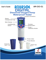
Figure 2 - Probe Component Identification for Maintenance Purposes
VP Connector (AK9 Connector for ISM sensor)
Pg 13.5 Threaded Sleeve
Washer
O-ring
Anode
Cathode and Guard Ring
Membrane Body
Cap Sleeve
Protective Cap

8
SPECIFICATIONS
Sample Flowrate 50 – 1000 mL/min
Sample Temperature: 0 – 60 °C (32 – 140 °F) for compensation; can tolerate 100 °C (212 °F)
Sample Pressure: 0 – 5 bar (0 – 72 psig)
Sample Connections: 1/4” NPTF
Wetted Materials: p
olyacetal flow housing, polyphenylene sulfide probe, PTFE
membrane (reinforced with stainless steel mesh and silicone rubber),
Viton and silicone rubber o-rings
Cable length:
M300 & M300ISM up to 33 ft (10 m)
770MAX up to 300 ft (91 m)
2000 up to 200 ft (61 m)
Weight: 0.5 lb (1 kg)
System Accuracy: ±1% of reading or 1 ppb, whichever is greater
Response Time: 98% response in 90 seconds
Measurement Range: 0 – 10,000 ppb (µg/L) with auto-ranging
S
PARE PARTS
Replacement probe (analog) 52 201 067
Replacement ISM probe 52 201 209
Electrolyte (25 mL bottle) 34 100 2016
Membrane kit including electrolyte, 4 membranes and o-ring sets 52 200 024
Single membrane body 52 200 071
Replacement preamp for 2000 Instrument 58 037 203 (367-201)
Replacement preamp for 770MAX Instrument 58 037 011 (357-201)
Replacement flow housing 58 084 009 (17490)
Replacement VP cables for M300 Instrument
1 m 52 300 107
3 m 52 300 108
5 m 52 300 109
10 m 52 300 110
Replacement AK9 cables for M300 ISM Instrument
1 m 100000102
3 m 100000302
5 m 100000502
10 m 100001002
Accessory Polarization Module (analog sensor) 52 200 893

9
OXYGEN SOLUBILITY
Air-saturated water at 1 atmosphere, 760 mmHg
Temperature
(°
°°
°C)
Oxygen Concentration
(mg/L)
0
14.57
1
14.17
2
13.79
3
13.43
4
13.08
5
12.74
6
12.42
7
12.11
8
11.82
9
11.53
10
11.26
11
11.00
12
10.75
13
10.50
14
10.27
15
10.05
16
9.84
17
9.63
18
9.43
19
9.24
20
9.06
21
8.89
22
8.72
23
8.55
24
8
.39
25
8.24
26
8.10
27
7.95
28
7.82
29
7.68
30
7.55
31
7.43
32
7.31
33
7.19
34
7.07
35
6.96
36
6.85
37
6.74
38
6.63
39
6.53
40
6.43
41
6.33
42
6.23
43
6.13
44
6.04
45
5.94
46
5.85
47
5.76
48
5.66
49
5.57
50
5.48
ALTITUDE VS PRESSURE
If calibration is performed at high elevations and
a barometer is not available, this table provides
an approximate atmospheric pressure setting.
Altitude
(ft) (m)
Atmospheric
Pressure
(mmHg)
-500 -152 773
0 0 760
500 152 747
1000 305 734
2000 610 708
3000 914 682
4000 1219 666
5000 1524 642
6000 1829 619

10
WARRANTY
This Warranty is given expressly and in lieu of all other warranties, express or implied. The Buyer agrees
that there is no warranty of merchantability and that there are no other warranties, express or implied,
which extend beyond the description on the face of this agreement.
Mettler-Toledo Thornton, Inc. (hereinafter referred to as The Company) warrants to the original Buyer
each electrode, component, or instrument manufactured and/or sold by The Company to be free from
defects in material and workmanship in normal use and service for a period of one (1) year from
shipment, unless expressly stated otherwise by the product packaging or expressly agreed to in advance
by the Company. The obligation of The Company under this warranty is limited to repair or replacement of
the defective product at The Company’s discretion. All warranty claims shall be returned to The Company
pursuant to The Company’s Returned Goods Authorization program. Shipping costs (including return
shipping) are the responsibility of The Buyer. The Company assumes no responsibility for any direct or
indirect costs associated with removal of defective products, or re-installation of replacement products.
The Company shall not be responsible for damage to any electrode, component, or instrument resulting
from misuse, negligence, accident or resulting from repairs, alterations, or installations made by any
person or firm not duly authorized by The Company. No agent is authorized to assume for The Company
any liability except as above set forth. The Company warrants that services will be performed in a
workmanlike manner in conformity with standard industry practice. Should any nonconformity be
detected within 30 days after the work is completed and prompt notification is made by Buyer in writing to
the Company, Company will supply the necessary service, direction, or consultation to correct the
nonconformity.
Returned Goods Policy: A Returned Material Authorization (RMA) number must accompany all returned
goods. This authorization is obtained by calling our Technical Service (800) 510-7873 or (781) 301-8600.
All transportation costs on authorized returns must be prepaid. Authorized replacement parts sent prior to
receipt and evaluation of merchandise being returned will be invoiced in full. Credit will be issued only
after the returned part is received and evaluated by factory personnel. The Company is not responsible
for products returned without proper authorization.
Factory Restocking Charge: Items returned to The Company more than 30 days after shipment will be
subject to a 25 % restocking charge, plus any additional charges for refurbishment to salable condition.
The Company will not accept returns more than 90 days after shipment, unless returned under warranty
or for non-warranty repair.
Special Products: Cancellation or return of special products will not be accepted.
Disclaimer of Damages:
In no event shall The Company be liable for any type of special consequential, incidental or penal
damages, whether such damages arise out of or are a result of breach of contract, warranty, tort
(including negligence), strict liability or otherwise. Such damages shall include, but not be limited to loss
of profits or revenues, loss of use of the equipment or associated equipment, cost of substitute
equipment, facilities, down time costs, increased construction costs or claims of The Buyer’s customers or
contractors for such damages. The Buyer agrees that in the event of a transfer, assignment, or lease of
the equipment sold hereunder The Buyer shall secure for The Company the protection afforded to it in
this paragraph.


Mettler-Toledo Thornton, Inc.
36 Middlesex Turnpike
Bedford, MA 01730 USA
Tel. +1-781-301-8600
Fax +1-781-301-8701
Toll Free +1-800-510-PURE ( US and Canada only)
thornton.info@mt.com
© Mettler-Toledo Thornton, Inc. 2012
OM52201072 Rev.F 09/12 www.mt.com/thornton
/