Page is loading ...

A trusted leader in measurement
and calibration solutions.
875 Bassett Road
Westlake | Ohio | 44145 | USA
(800) 817-7849
WesternEnterprises.com
Meriam.com
© Western / Scott Fetzer Co. 2020
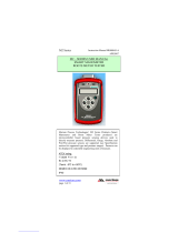
User Manual
M/MX
Smart Manometer
With Altimeter and Air Speed Tester
M
2003

9R724-A ECN-18485 January 2020
User Manual M2003/M2003X Smart Manometer with Altimeter & Air Speed Test 2 of 87
Contents
General Information ...................................................................................................................................4
Notification Statements ...................................................................................................4
Glossary ...................................................................................................................................... 5
General warnings and cautions .......................................................................................................7
Preventing injury ..................................................................................................................7
Safety symbols .......................................................................................................................7
Sample label for General Purpose Smart Manometers ...........................8
Fire or explosion hazard .................................................................................................. 8
For General Purpose Series .........................................................................................8
Do not exceed pressure limits ................................................................................. 11
Sensors ..............................................................................................................................................................12
Meriam Tethered Sensors (MTS) ...........................................................................14
How to zero Absolute Sensors ................................................................................14
How to zero DN, DI, or CI sensors ........................................................................16
Altitude and Indicated Air Speed ................................................................................................ 17
ALT FEET or BEYOND MAX ...................................................................................... 17
IAS MPH .................................................................................................................................17
Altitude Correction in Feet (Meters) ................................................................... 18
Sea Level Correction in Meters ..............................................................................19
Switch to MTS ..............................................................................................................................................21
Smart Manometer .....................................................................................................................................22
Battery and USB power ................................................................................................22
Batteries ...................................................................................................................................22
The display .............................................................................................................................24
Keypad: Description of the keys ............................................................................ 26
The backlight ........................................................................................................................28
Measurement units ..........................................................................................................30
Damping .................................................................................................................................. 31
Data Logging........................................................................................................................32
Leak Test .................................................................................................................................33
Relief Valve Test .................................................................................................................36
Display information from two sensors ...............................................................37
Auto O (Automatic shut o) ...................................................................................38
What does the Zero (ø) key do? ............................................................................. 39
meriSuite CG application ................................................................................................................... 40
How does meriSuite CG benefit you? ................................................................40
meriSuite CG and USB Drivers required ..........................................................40
Tips for using meriSuite CG ......................................................................................41
Connection status.............................................................................................................44
Configuration button ......................................................................................................46
User Calibration button ................................................................................................50
Data Log button ................................................................................................................. 52
TSV file format .....................................................................................................................54

9R724-A ECN-18485 January 2020
User Manual M2003/M2003X Smart Manometer with Altimeter & Air Speed Test 3 of 87
Application button ............................................................................................................ 65
Update button ......................................................................................................................66
Specifications ..............................................................................................................................................67
Sensors: type and range ..............................................................................................67
Meriam Tethered Sensors: type and range ....................................................68
Overrange limit ................................................................................................................... 70
Temperature .......................................................................................................................... 70
Relative Humidity .............................................................................................................. 70
Vibration ..................................................................................................................................70
Ingress specifications .................................................................................................... 70
Altitude specifications ................................................................................................... 71
Indicated Air Speed specifications.......................................................................71
Keypad ...................................................................................................................................... 71
Media Compatibility ........................................................................................................72
Battery Type ..........................................................................................................................72
EMC compliance ...............................................................................................................77
Dimensional specifications ........................................................................................78
Dimensional specifications (continued) ...........................................................79
Weight ....................................................................................................................................... 79
Enclosure ................................................................................................................................79
Maintenance and cleaning ................................................................................................................84
Cleaning ...................................................................................................................................84
Prepare the Smart Manometer for storage .................................................... 84
Help .......................................................................................................................................................................85
Register your product .................................................................................................... 85
Find downloads and documents ...........................................................................85
Returning for repair or calibration ........................................................................86
Western Contact Information .........................................................................................................87

9R724-A ECN-18485 January 2020
User Manual M2003/M2003X Smart Manometer with Altimeter & Air Speed Test 4 of 87
General Information
Notification Statements
Disclaimer
Every precaution has been taken in the preparation of this
manual. Nevertheless, Meriam assumes no responsibility for
errors or omissions or any damages resulting from the use of
the information contained in this publication, including, without
limitation, incidental, special, direct or consequential damages.
MERIAM MAKES NO REPRESENTATIONS OR WARRANTIES
WITH RESPECT TO THE ACCURACY OR COMPLETENESS OF
THE CONTENTS HEREOF AND SPECIFICALLY DISCLAIMS ANY
IMPLIED WARRANTIES OF MERCHANTABILITY OR FITNESS
FOR ANY PARTICULAR PURPOSE. Meriam reserves the right to
revise this publication and to make changes from time to time in
the content hereof without obligation to notify any person of such
revision or changes.
In no event shall Meriam be liable for any indirect, special,
incidental, consequential, or punitive damages or for any lost
profits arising out of or relating to any services provided by
Meriam or its ailiates.
It is not possible for Meriam to identify all foreseeable uses or
misuses, therefore all persons involved in commissioning, using,
or maintaining this product must satisfy their self that each
intended application is acceptable.
Copyright
This publication is proprietary to Meriam and no ownership
rights are transferred. Neither this manual, nor any of the material
contained herein, may be reproduced without the prior written
consent of Meriam.
Trademark information
Design Patent D769,141 for the Smart Manometer’s LCD display.
All other trademarks are the property of their respective owners.

9R724-A ECN-18485 January 2020
User Manual M2003/M2003X Smart Manometer with Altimeter & Air Speed Test 5 of 87
Glossary
Words and phrases with their definitions or explanations.
Words &
phrases
Definitions or explanations
Blinking • It indicates the active edit field on an edit
screen.
• It indicates the displayed value is not actively
changing (like Hold or stopped Test).
FS • FS is the abbreviation of Full Scale.
Home • Home is the first screen that displays after
turning on the Smart Manometer. It’s the
screen with measurements and units on it.
• After you press the Home key in many other
screens, the Smart Manometer returns you to
Home.
Key and
button
• A key refers to hardware push-buttons on the
keypad that you can press.
• A button refers to an area in meriSuite CG that
you can tap or click to select functions.
Isolated • The word isolated refers to the sensing
element being separated from the media. It
is commonly used in the phrases Absolute
Isolated (AI) pressure and Compound Isolated
(CI) pressure.
Customer
Calibration
• Customer calibration refers to any calibration
done outside of Meriam with non-Meriam
traceability.
• Customer calibration includes: Multipoint
calibration or adjustment.
Meriam
Tethered
Sensor (MTS)
• A Meriam Tethered Sensor (MTS) always
refers to an external pressure sensor P2 or to
an external temperature sensor T2.
-- P1 -- • P1 on the display always refers to the internal
sensor.
-- P2 --
or
--t2--
• P2 on the display always refers to the external
pressure sensor.
• T2 on the Smart Manometer display always
refers to the MTS RTD temperature sensor.
p1.P2 • Data from the internal and external pressure
sensors display in two lines on the Smart
Manometer at the same time.
P1.T2 • Data from the internal pressure sensor and
MTS temperature RTD sensor display on the
Smart Manometer at the same time.

9R724-A ECN-18485 January 2020
User Manual M2003/M2003X Smart Manometer with Altimeter & Air Speed Test 6 of 87
Words &
phrases
Definitions or explanations
DIFF P1-P2 • The displayed result of the external pressure
measurement subtracted from the internal
pressure measurement.
Diff p2-p1 • The displayed result of the internal pressure
measurement subtracted from the external
pressure measurement.
--out- • --out- displays on the process readout
when the information readout is providing
information about exiting tests.
*P1 • The asterisk displays when you enable the
Sea Level Correction oset or enable the
Altitude Correction oset.

9R724-A ECN-18485 January 2020
User Manual M2003/M2003X Smart Manometer with Altimeter & Air Speed Test 7 of 87
General warnings and cautions
Preventing injury
Failure to follow all instructions could result in injury:
Read directions
before using
▪Read the entire manual before using the Smart Manometer.
▪Understand the contents before using the Smart Manometer.
▪Follow all safety warnings and instructions provided with this
product.
Safety symbols
The following table defines the safety symbols, signal words,
and corresponding safety messages used in the manual. These
symbols:
▪Identify potential hazards.
▪Warn you about hazards that could result in personal injury or
equipment damage.
Safety symbols Explaining the symbols
DANGER
!
Indicates a potentially hazardous situation
which, if not avoided, will result in death or
serious injury.
WARNING
!
Indicates a potentially hazardous situation
which, if not avoided, could result in death
or serious injury.
CAUTION
!
Indicates a potentially hazardous situation
which, if not avoided, could result in minor
or moderate injury.
NOTICE
Indicates information essential for
proper product installation, operation or
maintenance.

9R724-A ECN-18485 January 2020
User Manual M2003/M2003X Smart Manometer with Altimeter & Air Speed Test 8 of 87
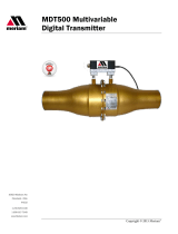
Sample label for General Purpose Smart
Manometers
All M2003 Series models are available for general-purpose use.
General Purpose (GP) versions are identified by the name plate
located on the rear of the unit under the protective rubber boot. A
sample of the General Purpose name plate is shown below:
USA
|designed|engineered|assembled
+ 1 2162811100
(800)817-7849
Meriam | 10920 Madison Avenue
Cleveland |Ohio | USA | 44102
Meriam.com
For repair or calibration |
General Purpose
Four 1.5 V alkaline AA batteries
Operating Temperature:
–10 ºC < Ta < 50 ºC
Refer to manual for use and
safety precautions.
For use only
in non-hazardous
locations.
WARNING
!
Fire or explosion hazard
DANGER
!
▪Do not use General Purpose versions in hazardous areas.
▪Do not use General Purpose versions in areas that may
contain flammable gas or vapors, combustible dusts or
ignitable fibers where an unintended spark can cause a fire or
explosion.
For General Purpose Series
CAUTION
!
Substitution of components may impair operation and safety.
▪Disconnect power before servicing.
▪Do not power the Smart Manometer with a combination of
new and old batteries.
▪Do not power the Smart Manometer with a combination of
batteries from dierent manufacturers.

9R724-A ECN-18485 January 2020
User Manual M2003/M2003X Smart Manometer with Altimeter & Air Speed Test 9 of 87
Sample label for Intrinsically Safe Smart
Manometers
Intrinsically Safe—M2003X Marking
Intrinsically Safe versions are identified by the nameplate located
on the battery door. A sample of the Intrinsically Safe nameplate is
shown below:
Intrinsically Safe Manometers
M2003X Smart Manometer
Directives for the proper use of equipment are located on
9R698-Intrinsically Safe Control Drawing that accompanies each
M2003X shipped.
• Component substitution may impair Intrinsic Safety.
• Repairs must be made at Meriam to retain the Intrinsic Safety
Certification.
• Service gauges only in a safe location.
• Replace batteries only in a safe location.

9R724-A ECN-18485 January 2020
User Manual M2003/M2003X Smart Manometer with Altimeter & Air Speed Test 10 of 87
Sample label for Intrinsically Safe Tethered
Sensors
Intrinsically Safe—MTSX Marking
See the figure of a sample label below.
Intrinsically Safe tethered sensors
MTSX Meriam Tethered Sensors
Directives for the proper use of equipment are located on
9R699-Intrinsically Safe Control Drawing that accompanies each
MTSX shipped.
• Component substitution may impair Intrinsic Safety.
• Repairs must be made at Meriam to retain the Intrinsic Safety
Certification.
• Service sensors only in a safe location.

9R724-A ECN-18485 January 2020
User Manual M2003/M2003X Smart Manometer with Altimeter & Air Speed Test 11 of 87
Do not exceed pressure limits
WARNING
!
▪Do not exceed the Pressure Limits listed in the Specifications
section of this manual.
▪Failure to operate within the specified pressure limit could
result in minor or moderate injury.

9R724-A ECN-18485 January 2020
User Manual M2003/M2003X Smart Manometer with Altimeter & Air Speed Test 12 of 87
Sensors
Overview of Sensors
This Smart Manometer can display two measurements: one from
the internal sensor and one from the optional tether sensor.
NOTICE
▪P1 on this Smart Manometer always refers to the internal
sensor.
▪P2 or T2 on this Smart Manometer always refers to the
external sensor.
Use two wrenches to install or remove pressure
connections
Connection: 1/8 in. female NPT, 316L SS.
▪Always use a 3/4 in. wrench on the pressure manifold when
you install or remove the 1/8 in. NPT fitting.
▪Applying torque to the manifold can damage the plastic
enclosure and voids the warranty.
▪Do not over tighten.
Carefully equalize the pressure
Avoid these two issues with dierential sensors:
1. Connecting pressure to the incorrect pressure port on DN or
DI dierential pressure modules may cause damage to the
pressure sensor.
2. Applying pressure to either port before both connections are
made.
NOTICE
Apply pressure to both dierential ports at the same time.
Note: See Overrange limit in the section called Specifications
concerning overrange pressure limits. If over pressure damage
occurs, you must return the Smart Manometer to the factory for
sensor replacement.

9R724-A ECN-18485 January 2020
User Manual M2003/M2003X Smart Manometer with Altimeter & Air Speed Test 13 of 87
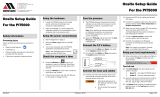
Sensor manifold types
ZMTS-ANXXXX
ZM2003-ANXXXX
ZMTS-AIXXXX
ZM2003-AIXXXX
ZMTS-DNXXXX ZMTS-DIXXXX
ZMTS-CNXXXX ZMTS-CIXXXX
ZMTS-RTD

9R724-A ECN-18485 January 2020
User Manual M2003/M2003X Smart Manometer with Altimeter & Air Speed Test 14 of 87
Meriam Tethered Sensors (MTS)
Overview of the temperature and pressure sensors
1. The P2 sensor and the T2 sensor can be displayed with the P1
sensor.
2. When two sensors are displayed, no Units are displayed and
the Units key is disabled.
3. The Zero key is also disabled.
4. When a single sensor is selected it displays the measurement
units that were selected in meriSuite CG.
Make an electrical connection
▪Align the red dot on the Smart Manometer with the red dot on
the Tether cable and push in.
▪Align the red dot on the MTS with the red dot on the Tether
cable and push in.
How to zero Absolute Sensors
Overview of the zeroing Absolute Sensors
The Smart Manometer is a stable and precise instrument.
However, on occasion the Smart Manometer should have a new
zero taken. The new zero removes a zero drift that can occur after
the Smart Manometer was last zeroed. The Smart Manometer can
be zeroed only if the new applied zero is within ± 1 % FS of the
original factory calibration zero. This prevents accidental zeroing
at atmospheric pressure or other relatively high pressures. If the
Smart Manometer is outside this limit, the Smart Manometer
cannot zero.
1. Referenced to Absolute Zero - This traditional and preferred
method takes a snapshot of the measured pressure when a
vacuum of less than 100 microns Absolute is applied to the
sensor.
2. Restore Factory Zero - This method restores the calibration
curve to the original zero taken at the factory.
Note: This feature is intended for comparison purposes, and
should not be used for real pressure measurement. This feature
does not compensate for any zero drift.
3. User Defined Oset (Zero) - With this method, you can
enter any pressure value when a known reference is applied
(for example: the local barometric pressure). The Smart
Manometer compares its actual measured value with the

9R724-A ECN-18485 January 2020
User Manual M2003/M2003X Smart Manometer with Altimeter & Air Speed Test 15 of 87
entered value and calculate a new zero reference based on the
oset.
Steps for zeroing Absolute Sensors
You can zero the Smart Manometer in one of three ways. The
following may appear in a dierent order depending on which
arrow key you press. When an absolute sensor displays on-screen
as P1 or P2, press the Zero key to see one of the three sets of
characters below and the following three messages
On-screen
message Explanations
TAP TO
CHOOSE REF
• Tapping the Accept key selects the displayed
reference.
ARROWS TO
CHANGE REF
• Tapping an Arrow key changes the displayed
reference.
X Cancels
• Tapping the Cancel key cancels the zero
request.
ab5 0 • This is the on-screen abbreviation for
Absolute Zero.
dflt • This is the on-screen abbreviation for Default.
• If you want to restore the Factory Zero on a
sensor, press the Accept key when you see
these characters appear.
u5Er 0 • This refers to User Defined Oset (Zero). You
can set an absolute reference point other than
zero.

9R724-A ECN-18485 January 2020
User Manual M2003/M2003X Smart Manometer with Altimeter & Air Speed Test 16 of 87
How to zero DN, DI, or CI sensors
1. Disconnect from a pressure source and vent the pressure port
to atmosphere.
1. Do not remove the factory installed P2 plug if it is present.
2. The display should read close to zero.
2. Press the Zero key.
The top line displays dashes ------.
3. The process is complete when the Smart Manometer returns
to the Home (Measurement Units) screen.
4. If someone has turned on the Password Required For Future
Access feature in meriSuiteCG, the password feature does
not prevent you from zeroing the Smart Manometer.
Note: You can only zero the Smart Manometer if the new zero
value is within ± 5 % (of FS) of the original factory calibrated
zero. If the zero procedure generates a new zero reference
outside this limit, the procedure fails. Factory service may be
required.
5. You can turn o the Zero function in meriSuite CG by
deselecting Allow zero adjust (Ø) in the Display Functions list.

9R724-A ECN-18485 January 2020
User Manual M2003/M2003X Smart Manometer with Altimeter & Air Speed Test 17 of 87
Altitude and Indicated Air Speed
ALT FEET or BEYOND MAX
When BEYOND MAX appears on screen
When BEYOND MAX appears on-screen instead of ALT FEET, the
calculated altitude exceeds 36 000 feet.
Note: Don’t confuse BEYOND MAX with an overrange condition.
If the sensor is outside the calibrated range, the M2003 displays
MEAS ERROR and the sensor may be damaged.
Display altitude in feet or meters
1. Press the Backward key to display ALT FEET (Altitude in Feet).
2. Press the Units key when ALT FEET is on-screen to switch
between FEET and METER and back to FEET.
IAS MPH
When you display IAS MPH (KNOTS or KM/H) on-screen, the
current, ambient pressure—the uncorrected barometric pressure—
is measured and is the reference pressure used for calculating air
speed.
When you switch from the IAS MPH screen to one of the other
display functions, the M2003 does not hold that measurement in
memory. When you switch back to the IAS MPH screen, a new
pressure measurement is recorded and used as the reference
barometric pressure in the IAS MPH calculated air speed.
Switching from the IAS MPH screen to another display function,
and then switching back to the IAS MPH screen again while in
motion (IAS > 0), displays the wrong speed since IAS is reset
to zero (current measured pressure to reference barometric
pressure).
1. Press Backward two times from the home screen to display
IAS MPH (mi/h).
2. Press Units key when IAS MPH is on-screen to switch from
MPH to KNOTS to KM/H and back to MPH.

9R724-A ECN-18485 January 2020
User Manual M2003/M2003X Smart Manometer with Altimeter & Air Speed Test 18 of 87
Altitude Correction in Feet (Meters)
This User Defined Altitude function is useful in determining an
elevation change from a map elevation reference or from a survey
trig marker elevation. Follow the on-screen instructions to set up
the M2003 to display altitude based on data you enter.
1. Press the Backward key three times from the home screen to
display ALTITUDE CORRECTION IN FEET TAP √ TO CHANGE.
2. Press the Accept (√ ) key to enter the change screen.
3. The M2003 displays the following message:
ENABLE ALTITUDE OFFSET? √-YES X-NO
1. Pressing the Cancel (X) key returns you to the ALTITUDE
CORRECTION IN FEET TAP √ TO CHANGE screen.
2. Pressing the Accept (√) key displays Altitude Oset
options:
Note: When you Enable the Altitude Oset, an asterisk (*)
appears on the Home, the ALT FEET, and IAS MPH screens
to indicate that either an Altitude Oset or Sea Level Oset
has been set or both of Osets have been set. Pressing the
Information key displays ON or OFF for each active oset so
you can easily determine which osets are active.
4. The M2003 displays the following message:
ALT OFFSET IN FEET √ SAVES X CANCELS 0 CLEARS
1. Pressing the Up or Down arrows on the keypad changes
the first digit and pressing the Right or Left arrows moves
the blinking cursor right or left. Enter your Defined Altitude
data by using the arrow keys.
2. Information: 0 Clears refers to the Zero key. Pressing it
clears any numbers you entered after pressing the Up or
Down arrow keys.

9R724-A ECN-18485 January 2020
User Manual M2003/M2003X Smart Manometer with Altimeter & Air Speed Test 19 of 87
3. Information: Pressing the Cancel (X) key returns you to
the ALTITUDE CORRECTION IN FEET TAP √ TO CHANGE
screen.
4. Information: The Accept key saves your ALT OFFSET IN
FEET data.
Sea Level Correction in Meters
Important: You can’t change from meters to feet; Sea Level
Correction is always in meters.
1. Press the Backward key four times from the home screen to
display the following message:
SEA LEVEL CORRECTION IN METERS TAP TO CHANGE.
1. ENABLE SEA LEVEL OFFSET? √-YES X-NO
2. NO returns you to the SEA LEVEL CORRECTION IN
METERS TAP TO CHANGE screen.
3. YES takes you to the edit screen. Pressing the Up or Down
arrows on the keypad changes the first digit and pressing
the Right or Left arrows moves the blinking cursor right
or left. Enter your Sea Level Correction data by using the
arrow keys.
4. While in the edit screen, the M2003 displays the
following message: SEA LEVEL CORRECTION √ SAVES
XCANCELS 0CLEARS

9R724-A ECN-18485 January 2020
User Manual M2003/M2003X Smart Manometer with Altimeter & Air Speed Test 20 of 87
5. Information: 0 Clears refers to the Zero key. Pressing it
clears any numbers you entered after pressing the Up or
Down arrow keys.
6. Information: Pressing the Cancel (X) key returns you to
the ALTITUDE CORRECTION IN FEET TAP √ TO CHANGE
screen.
7. Information: The Accept key saves your ALT OFFSET IN
FEET data.
Note: Barometric pressures provided by the National Weather
Service and used at airports are always corrected to sea level.
Note: When you Enable the SEAL LEVEL CORRECTION Oset,
an asterisk (*) appears on the Home, the ALT FEET, and IAS
MPH screens to indicate that either an Altitude Oset or Sea
Level Oset has been set or both of Osets have been set.
/