Page is loading ...

201-10802-01
March 2006
NETGEAR, Inc.
4500 Great America Parkway
Santa Clara, CA 95054 USA
Model FSM7328S,
FSM7352S, and FSM7352PS
Managed Stackable Layer 3
Fast Ethernet Switches
Hardware Installation Guide

Publication Version 1.0, March 2006
© 2006 by NETGEAR, Inc. All rights reserved. Information is subject to change without notice.
Trademarks
The Netgear Logo, the Gear Guy, Everybody’s connecting, and ProSafe are trademarks or registered trademark of
Netgear, Inc. in the United States and other countries. Microsoft, Windows, and the Windows logo are trademarks or
registered trademarks of Microsoft Corporation in the United States and other countries. Other brand and product names
are trademarks or registered trademarks of their respective holders.
Statement of Conditions
In the interest of improving internal design, operational function, and/or reliability, NETGEAR reserves the right to
make changes to the products described in this document without notice.
NETGEAR does not assume any liability that may occur due to the use or application of the product(s) or circuit
layout(s) described herein.
Certificate of the Manufacturer/Importer
It is hereby certified that the NETGEAR Model FSM7328S Managed Fast Ethernet Switch has been suppressed in
accordance with the conditions set out in the BMPT-AmtsblVfg 243/1991 and Vfg 46/1992.The operation of some
equipment (for example, test transmitters) in accordance with the regulations may, however, be subject to certain
restrictions. Please refer to the notes in the operating instructions.
It is hereby certified that the NETGEAR Model FSM7352S Managed Fast Ethernet Switch has been suppressed in
accordance with the conditions set out in the BMPT-AmtsblVfg 243/1991 and Vfg 46/1992.The operation of some
equipment (for example, test transmitters) in accordance with the regulations may, however, be subject to certain
restrictions. Please refer to the notes in the operating instructions.
It is hereby certified that the NETGEAR Model FSM73f2PS Managed Fast Ethernet Switch with PoE has been
suppressed in accordance with the conditions set out in the BMPT-AmtsblVfg 243/1991 and Vfg 46/1992.The operation
of some equipment (for example, test transmitters) in accordance with the regulations may, however, be subject to
certain restrictions. Please refer to the notes in the operating instructions.
Federal Office for Telecommunications Approvals has been notified of the placing of this equipment on the market
and has been granted the right to test the series for compliance with the regulations.
Voluntary Control Council for Interference (VCCI) Statement
This is Class A product based on the standard of the Voluntary Control Council for Interference by Information
Technology Equipment (VCCI). If this equipment is used in a domestic environment, radio interference may occur, in
which case, the user may be required to take corrective actions.”
Federal Communications Commission (FCC) Compliance Notice: Radio Frequency Notice
This device complies with part 15 of the FCC Rules. Operation is subject to the following two conditions:
• This device may not cause harmful interference.
• This device must accept any interference received, including interference that may cause undesired operation.

Publication Version 1.0, March 2006
Note: This equipment has been tested and found to comply with the limits for a Class A digital device, pursuant to part
15 of the FCC Rules. These limits are designed to provide reasonable protection against harmful interference in a
residential installation. This equipment generates, uses, and can radiate radio frequency energy and, if not installed and
used in accordance with the instructions, may cause harmful interference to radio communications. However, there is no
guarantee that interference will not occur in a particular installation. If this equipment does cause harmful interference to
radio or television reception, which can be determined by turning the equipment off and on, the user is encouraged to try
to correct the interference by one or more of the following measures:
• Reorient or relocate the receiving antenna.
• Increase the separation between the equipment and receiver.
• Connect the equipment into an outlet on a circuit different from that which the receiver is connected.
• Consult the dealer or an experienced radio/TV technician for help.
Canadian Department of Communications Radio Interference Regulations
This digital apparatus (ProSafe 24-Port 10/100 LE managed Stackable Switch with 4 Gigabit Ports FSM7328PS) does
not exceed the Class A limits for radio-noise emissions from digital apparatus as set out in the Radio Interference
Regulations of the Canadian Department of Communications.
This digital apparatus (ProSafe 48-Port 10/100 LE managed Stackable Switch with 4 Gigabit Ports FSM7352S) does not
exceed the Class A limits for radio-noise emissions from digital apparatus as set out in the Radio Interference
Regulations of the Canadian Department of Communications.
This digital apparatus (ProSafe 48-Port 10/100 LE managed Stackable Switch with 4 Gigabit Ports and PoE
FSM7352PS) do not exceed the Class A limits for radio-noise emissions from digital apparatus as set out in the Radio
Interference Regulations of the Canadian Department of Communications.
Règlement sur le brouillage radioélectrique du ministère des Communications
Cet appareil numérique (ProSafe 24-Port 10/100 LE managed Stackable Switch with 4 Gigabit Ports FSM7328PS)
respecte les limites de bruits radioélectriques visant les appareils numériques de classe A prescrites dans le Règlement
sur le brouillage radioélectrique du ministère des Communications du Canada.
Cet appareil numérique (ProSafe 48-Port 10/100 LE managed Stackable Switch with 4 Gigabit Ports FSM7352S)
respecte les limites de bruits radioélectriques visant les appareils numériques de classe A prescrites dans le Règlement
sur le brouillage radioélectrique du ministère des Communications du Canada.
Cet appareil numérique (ProSafe 48-Port 10/100 LE managed Stackable Switch with 4 Gigabit Ports and PoE
FSM7352PS) respecte les limites de bruits radioélectriques visant les appareils numériques de classe A prescrites dans le
Règlement sur le brouillage radioélectrique du ministère des Communications du Canada.
Customer Support
Refer to the Support Information Card that shipped with your Managed Stackable
Layer 3 Fast Ethernet Switch.
World Wide Web
NETGEAR maintains a World Wide Web home page that you can access at the
universal resource locator (URL) http://www.netgear.com. A direct connection to
the Internet and a Web browser such as Internet Explorer or Netscape are required.

Publication Version 1.0, March 2006
Product and Publication Details
Model Number: FSM7328S, FSM7352S, and FSM7352PS
Publication Date: March 2006
Product Family: managed switch
Product Name: Managed Stackable Layer 3 Fast Ethernet Switch
Home or Business Product: Business
Language: English
Publication Part Number: 201-10802-01
Publication Version Number 1.0

Publication Version 1.0, March 2006
v
Contents
Chapter 1
About This Manual
Audience, Scope, Conventions, and Formats ................................................................1-1
Chapter 2
Introduction
FSM7328S Front Panel and LEDs .................................................................................2-1
FSM7328S Rear Panel ...................................................................................................2-3
FSM7352S Front Panel and LEDs .................................................................................2-3
FSM7352S Rear Panel ...................................................................................................2-4
FSM7352PS Front Panel and LEDs ...............................................................................2-5
FSM7352PS Rear Panel ..........................................................................................2-7
Safety Instructions ..........................................................................................................2-7
Chapter 3
Hardware Installation
Package Contents ..........................................................................................................3-1
Protecting Against Electrostatic Discharge .....................................................................3-2
Unpacking the Hardware ................................................................................................3-2
Installation ......................................................................................................................3-4
Select a Location ......................................................................................................3-4
Install the Switch ......................................................................................................3-5
Check the Installation ...............................................................................................3-6
Connect to Power and Check the LEDs ...................................................................3-7
Stacking Switches ..........................................................................................................3-7
Connecting a Redundant Power Supply to the FSM7352PS .........................................3-8
Connecting Equipment to the Switch ..............................................................................3-9
RJ-45 Ports ..............................................................................................................3-9
Gigabit Module Bay .................................................................................................3-9
Connecting a Console to the Switch .............................................................................3-10

Publication Version 1.0, March 2006
vi
Chapter 4
Troubleshooting
Troubleshooting Chart ...................................................................................................4-1
Additional Troubleshooting Suggestions .......................................................................4-2
Appendix A
Technical Specifications ......................................................................................................A1
Appendix B
Default Configuration Settings............................................................................................B1

1-1
v1.0, March 2006
Chapter 1
About This Manual
The FSM7328S, FSM7352S, and FSM7352PS Managed Stackable Layer 3 Fast
Ethernet Switches Hardware Installation Guide contains information for set up
and management of the NETGEAR® FSM7328S, FSM7352S, and FSM7352PS
switches.
Audience, Conventions, Formats, and Scope
This information is intended for network managers familiar with network
management concepts and terminology. This guide uses the following
typographical conventions:
This guide uses the following formats to highlight special messages:
Table 1-1. Typographical Conventions
Italics Emphasis, books, CDs, URL names
Bold User input
Fixed Screen text, file and server names, extensions, commands, IP
addresses
Note: This format is used to highlight information of importance or
special interest.
Tip: This format is used to highlight a procedure that will save time or
resources.

Managed Stackable Layer 3 Fast Ethernet Switches Hardware Installation Guide
1-2 About This Manual
v1.0, March 2006
This manual is written according to these specifications:
Warning: Ignoring this type of note may result in a malfunction or
damage to the equipment.
Danger: This is a safety warning. Failure to take heed of this notice may
result in personal injury or death.
Table 1-2. Manual Scope
Product version • ProSafe 24-Port 10/100 LE managed Stackable Switch
with 4 Gigabit Ports FSM7328PS
• ProSafe 48-Port 10/100 LE managed Stackable Switch
with 4 Gigabit Ports FSM7352S
• ProSafe 48-Port 10/100 LE managed Stackable Switch
with 4 Gigabit Ports and PoE FSM7352PS
Manual publication date March 2006
Note: Product updates are available on the NETGEAR, Inc. Web site at
http://kbserver.netgear.com.

Introduction 2-1
v1.0, March 2006
Chapter 2
Introduction
The NETGEAR Layer 3 Managed Stackable Fast Ethernet Switch is a state-of-
the-art, high-performance, IEEE-compliant network solution. It includes powerful
management features that you can use to eliminate bottlenecks, boost
performance, and increase productivity.
This guide describes hardware installation and basic troubleshooting for the
following NETGEAR switches:
•ProSafe 24-Port 10/100 LE managed Stackable Switch with 4 Gigabit Ports
FSM7328PS
• ProSafe 48-Port 10/100 LE managed Stackable Switch with 4 Gigabit Ports
FSM7352S
• ProSafe 48-Port 10/100 LE managed Stackable Switch with 4 Gigabit Ports
and PoE FSM7352PS
These switches can be free-standing, or rack-mounted in a wiring closet or an
equipment room. For information about features for each product, see the
NETGEAR Web site at http://www.netgear.com.
FSM7328S Front Panel and LEDs
The following figure shows the front panel of the FSM7328S. The front panel
contains LEDs, RJ-45 jacks, SFP module bays, stacking ports, and a console port.
Figure 2-1
SFP module bays Console portStacking portsRJ-45 jacks
LEDs

Managed Stackable Layer 3 Fast Ethernet Switches Hardware Installation Guide
2-2 Introduction
v1.0, March 2006
The following table shows the LEDs on the front panel of the switch.
Table 2-1. LED Descriptions for FSM7328S
LED Description
Master Green: This switch is the master of the stack.
Off: The switch is not the master of the stack.
Power Solid green: Power is supplied, and the switch is operating normally.
Blinking green: Runtime code load in progress.
Solid yellow: Power-On Self-Test (POST) in progress.
Blinking yellow: POST failure or CPU failure.
Off: Power is disconnected.
Fan
Solid red: Fan has failed.
Off: Fan is present and operating normally.
10/100M ports
One LED per port
Link/ACT/SPD LED
•Off: No 10/100 Mbps link is established on the port.
•Solid green: A valid 100 Mbps link is established on the port.
•Blinking green: The port is sending or receiving packets at
100 Mbps.
•Solid yellow: A valid 10 Mbps link is established on the port.
•Blinking yellow: The port is sending or receiving packets at 10
Mbps.
10/100/1000M
ports
two LEDs per port
Link/ACT LED
•Off: No 10/100/1000 Mbps link is established on the port.
•Solid green: A valid 1,000 Mbps link is established on the port.
•Solid yellow: A valid 10/100 Mbps link is established on the port.
•Blinking green: Packets transmission or reception is occurring on
the port at 1,000 Mbps.
•Blinking yellow: The port is sending or receiving packets at
10/100 Mbps.
Stack LED
•Green: Stack port has a valid link connection.
•OFF: Stack port does not have a valid link connection.
SFP port
(1000 Mbps only) •Solid green: Link is up.
•Blinking green: The port is sending or receiving a packet in link up
status .
•Off: No link is detected .

Managed Stackable Layer 3 Fast Ethernet Switches Hardware Installation Guide
Introduction 2-3
v1.0, March 2006
FSM7328S Rear Panel
The rear panel has a standard AC power receptacle for the supplied power cord.
FSM7352S Front Panel and LEDs
The following figure shows the front panel of the FSM7352S. The front panel
contains LEDs, RJ-45 jacks, SFP module bays, and stacking ports.
The following table shows the FSM7352S LEDs on the front of the switch.
Figure 2-2
Figure 2-3
Table 2-2. FSM7352S LED Description
LED Description
Master Green on: The switch is the master of the stack.
Yellow on: The switch is not the master of the stack.
Off: The switch is not part of a stack.
Fan Solid red: Fan has failed.
Off: Fan is present and operating normally.
power
Power receptacle
SFP module bays Stacking port
s
RJ-45 jacksLEDs

Managed Stackable Layer 3 Fast Ethernet Switches Hardware Installation Guide
2-4 Introduction
v1.0, March 2006
FSM7352S Rear Panel
The rear panel has a console port and a standard AC power receptacle for the
supplied power cord.
Power Solid green: Power is supplied, and the switch is operating normally.
Blinking green: Runtime code load in progress.
Solid yellow: Power-On Self-Test (POST) in progress.
Blinking yellow: POST failure or CPU failure.
Off: Power is disconnected.
10/100M ports
One LED per port
Link/ACT/SPD LED
•Off: No 10/100 Mbps link is established on the port.
•Solid green: A valid 100 Mbps link is established on the port.
•Blinking green: The port is sending or receiving packets at
100Mbps.
•Solid yellow: A valid 10 Mbps link is established on the port.
•Blinking yellow: The port is sending or receiving packets at 10
Mbps.
10/100/1000M
ports
Three LEDs per
port
Link/ACT LED
•Off: No 10/100/1000 Mbps link is established on the port.
•Solid green: A valid 1,000 Mbps link is established on the port.
•Solid yellow: A valid 10/100 Mbps link is established on the port.
•Blinking green: The port is sending or receiving packets at
1,000 Mbps.
•Blinking yellow: The port is sending or receiving packets at
10/100 Mbps.
Stack LED
•Green: Stack port has a valid link connection.
•Off: Stack port does not have a valid link connection.
SFP Port
(1,000 Mbps only) •Solid green: Link is up.
•Blinking green: The port is sending or receiving packets in link up
status.
• Off: No link is detected.
Figure 2-4
Table 2-2. FSM7352S LED Description (continued)
Power receptacleConsole port

Managed Stackable Layer 3 Fast Ethernet Switches Hardware Installation Guide
Introduction 2-5
v1.0, March 2006
FSM7352PS Front Panel and LEDs
The following figure shows the front panel of the FSM7352PS. The front panel
contains LEDs, RJ-45 jacks, SFP module bays, and stacking ports. The console
port is on the rear panel.
The following table describes the FSM7352PS LEDs on the front of the switch.
Figure 2-5
Table 2-3. FSM7352S LED Description
LED Description
ID This is the stack member ID (1–8) that the software assigns to the
switch.
Master Green on: This switch is the master of the stack.
Off: The switch is not part of a stack.
Fan Solid red: Fan has failed.
Off: Fan is present and operating normally.
Power Solid green: Power is supplied, and the switch is operating normally.
Solid yellow: Power-On Self-Test (POST) is in progress.
Blinking yellow: POST failure or CPU failure.
Off: Power is disconnected.
MAX PoE Solid yellow: Less than 15.4 W of PoE power is available.
Blinking yellow: The MAX PoE LED was active in the previous two
minutes.
Off: There is at least 7 W of PoE power available for another device.
RPS (redundant
power supply) Solid green: RPS bank supply PoE power.
Off: RPS bank is disconnected.
FSM7352PS
F
ron
t
P
ane
l
SFP StackingRJ-45 jacks portsmodule
bays
LEDs
1

Managed Stackable Layer 3 Fast Ethernet Switches Hardware Installation Guide
2-6 Introduction
v1.0, March 2006
10/100M Ports
One LED per
port
Right LED shows Link, Activity, and Speed
•Off: No 10/100 Mbps link is established on the port.
•Solid green: A valid 100Mbps link is established on the port.
•Blinking green: The port is sending or receiving packets at
100 Mbps.
•Solid yellow: A valid 10 Mbps link is established on the port.
•Blinking yellow: The port is sending or receiving packets at 10
Mbps.
Left LED shows PoE, and PoE fault
•Solid green: The PoE-powered device is connected, and the port is
supplying power successfully.
•Solid yellow: One of the following failures resulted in stopping power
to the port:
• Short circuit on PoE power circuit.
• PoE power demand exceeds power available.
• PoE current exceeds classification for PoE powered device.
• Out of proper voltage band (44–57 VDC).
•Off: No PoE-powered device connected.
10/100/1000M
ports
Three LEDs per
port
Copper Link, and Activity LED
•Off: No 10/100/1000 Mbps link is established on the port.
•Solid green: A valid 1,000 Mbps link is established on the port.
•Solid yellow: A valid 10/100 Mbps link is established on the port.
•Blinking green: The port is sending or receiving packets at
1000Mbps.
•Blinking yellow: The port is sending or receiving packets at
10/100Mbps.
SFP Link/ACT LED
•Off: No 1,000 Mbps link is established on the port.
•Solid green: A valid 1,000 Mbps link is established on the port.
•Blinking green: The port is sending or receiving packets at
1,000 Mbps.
Stack LED
•Green: The stack partner successfully established the link.
•Blinking green: The switch detects an active link, but the stack
partner failed to establish the link.
•Off: No link, or the switch is in non-stack mode.
Table 2-3. FSM7352S LED Description (continued)

Managed Stackable Layer 3 Fast Ethernet Switches Hardware Installation Guide
Introduction 2-7
v1.0, March 2006
FSM7352PS Rear Panel
The rear panel has a console port, a redundant power supply connector, and a
standard AC power receptacle for the supplied power cord.
Safety Instructions
Use the following safety guidelines to ensure your own personal safety and to help
protect your system from potential damage.
To reduce the risk of bodily injury, electrical shock, fire, and damage to the
equipment, observe the following precautions.
• Observe and follow service markings.
– Do not service any product except as explained in your system
documentation.
– Opening or removing covers that are marked with the triangular symbol
with a lightning bolt may expose you to electrical shock. Only a trained
service technician should service components inside these compartments.
• If any of the following conditions occur, unplug the product from the
electrical outlet and replace the part or contact your trained service provider:
– The power cable, extension cable, or plug is damaged.
– An object has fallen into the product.
– The product has been exposed to water.
– The product has been dropped or damaged.
– The product does not operate correctly when you follow the operating
instructions.
Figure 2-6
FSM7352PS Back Panel
Power receptacle
Console port Redundant power supply

Managed Stackable Layer 3 Fast Ethernet Switches Hardware Installation Guide
2-8 Introduction
v1.0, March 2006
• Keep your system away from radiators and heat sources. Also, do not block
cooling vents.
• Do not spill food or liquids on your system components, and never operate the
product in a wet environment. If the system gets wet, see the appropriate
section in your troubleshooting guide or contact your trained service provider.
• Do not push any objects into the openings of your system. Doing so can cause
fire or electric shock by shorting out interior components.
• Use the product only with approved equipment.
• Allow the product to cool before removing covers or touching internal
components.
• Operate the product only from the type of external power source indicated on
the electrical ratings label. If you are not sure of the type of power source
required, consult your service provider or local power company.
• To help avoid damaging your system, be sure that the voltage selection switch
(if provided) on the power supply is set to match the power available at your
location:
– 115 volts (V), 60 hertz (Hz) in most of North and South America and in
some Far Eastern countries such as South Korea and Taiwan
– 100 V, 50 Hz in eastern Japan and 100 V, 60 Hz in western Japan
– 230 V, 50 Hz in most of Europe, the Middle East, and the Far East
• Also, be sure that attached devices are electrically rated to operate with the
power available in your location.
• Use only approved power cables. If you have not been provided with a power
cable for your system or for any AC powered option intended for your system,
purchase a power cable that is approved for use in your country. The power
cable must be rated for the product and for the voltage and current marked on
the product's electrical ratings label. The voltage and current rating of the
cable should be greater than the ratings marked on the product.
• To help prevent electric shock, plug the system and peripheral power cables
into properly grounded electrical outlets.
• The peripheral power cables are equipped with three-prong plugs to help
ensure proper grounding. Do not use adapter plugs or remove the grounding
prong from a cable. If you must use an extension cable, use a three-wire cable
with properly grounded plugs.

Managed Stackable Layer 3 Fast Ethernet Switches Hardware Installation Guide
Introduction 2-9
v1.0, March 2006
• Observe extension cable and power strip ratings. Make sure that the total
ampere rating of all products plugged into the extension cable or power strip
does not exceed 80 percent of the ampere ratings limit for the extension cable
or power strip.
• To help protect your system from sudden, transient increases and decreases in
electrical power, use a surge suppressor, line conditioner, or uninterruptible
power supply (UPS).
• Position system cables and power cables carefully; route cables so that they
cannot be stepped on or tripped over. Be sure that nothing rests on any cables.
• Do not modify power cables or plugs. Consult a licensed electrician or your
power company for site modifications.
• Always follow your local and national wiring rules.
• Move products with care; ensure that all casters and stabilizers are firmly
connected to the system. Avoid sudden stops and uneven surfaces.

Managed Stackable Layer 3 Fast Ethernet Switches Hardware Installation Guide
2-10 Introduction
v1.0, March 2006

Hardware Installation 3-1
v1.0, March 2006
Chapter 3
Hardware Installation
This chapter explains how to install the hardware for the Managed Stackable
Layer 3 Fast Ethernet Switch models FSM7328S, FSM7352S, and FSM7352PS.
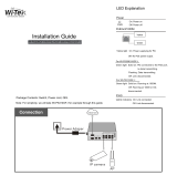
Package Contents
Each switch is packed and shipped separately. The package contains the following
items:
• Managed Stackable Layer 3 Fast Ethernet Switch with preinstalled software
• Power adapter cord
• Rack-mounting kit
• Null-modem serial cable (RS-232) with 9-pin connectors
• NETGEAR CD: The CD contains
– Configuration software
– Documentation including the Command Line Interface Reference for the
ProSafe 7300S Series Layer-3 Stackable Switches, the Administration
Manual for the ProSafe 7300S Series Layer-3 Stackable Switches, the
Quick Install Guide, and this Hardware Installation Guide
• Warranty and Support Card
• Quick Install Guide

Hardware Installation Guide for Managed Stackable Layer 3 Fast Ethernet Switches
3-2 Hardware Installation
v1.0, March 2006
Protecting Against Electrostatic Discharge
You can also take the following steps to prevent damage from electrostatic
discharge (ESD):
1. When unpacking a static-sensitive component from its shipping carton, leave
it in the antistatic package until you are ready to install it. Just before
unwrapping the antistatic package, discharge static electricity from your body.
2. Before moving a sensitive component, place it in an antistatic container or
package.
3. Handle all sensitive components in a static-safe area. If possible, use antistatic
floor pads, workbench pads, and an antistatic grounding strap.
Unpacking the Hardware
Check the contents of the boxes to make sure that all items are present before
beginning the installation.
1. Place the container on a clean flat surface and cut all straps securing the
container.
2. Unpack the hardware from the boxes.
Carefully remove the hardware and place it on a secure and clean surface. See
“Select a Location” on page 3-4.
3. Remove all packing material.
Warning: Static electricity can harm delicate components inside your
system. To prevent static damage, discharge static electricity
from your body before you touch any of the electronic
components, such as the microprocessor. You can do so by
periodically touching an unpainted metal surface on the
switch.
/