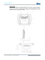
ADS-tec VMT5012 (2010) is a versatile industrial computer designed for demanding applications. With its powerful processor, ample memory, and rugged construction, it can handle complex tasks in harsh environments. The VMT5012 is ideal for use in industrial automation, data acquisition, and process control systems. It can also be used as a thin client or web server.
ADS-tec VMT5012 (2010) is a versatile industrial computer designed for demanding applications. With its powerful processor, ample memory, and rugged construction, it can handle complex tasks in harsh environments. The VMT5012 is ideal for use in industrial automation, data acquisition, and process control systems. It can also be used as a thin client or web server.


-
 1
1
-
 2
2
-
 3
3
-
 4
4
-
 5
5
-
 6
6
-
 7
7
-
 8
8
-
 9
9
-
 10
10
-
 11
11
-
 12
12
-
 13
13
-
 14
14
-
 15
15
-
 16
16
-
 17
17
-
 18
18
-
 19
19
-
 20
20
-
 21
21
-
 22
22
-
 23
23
-
 24
24
-
 25
25
-
 26
26
-
 27
27
-
 28
28
-
 29
29
-
 30
30
-
 31
31
-
 32
32
-
 33
33
-
 34
34
-
 35
35


ADS-tec VMT5012 (2010) User manual
- Type
- User manual
- This manual is also suitable for
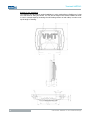
ADS-tec VMT5012 (2010) is a versatile industrial computer designed for demanding applications. With its powerful processor, ample memory, and rugged construction, it can handle complex tasks in harsh environments. The VMT5012 is ideal for use in industrial automation, data acquisition, and process control systems. It can also be used as a thin client or web server.
Ask a question and I''ll find the answer in the document
Finding information in a document is now easier with AI
Related papers
Other documents
-
Phoenix Contact UM EN OPC 7022 User manual
-
 Vicoustic VMT Mega Bass Trap Kti User manual
-
 adstec IWL3000 Series Quick Start Manuals
-
TEWS TPMC866-IO User manual
-
Vicoustic 2380x1190x20mm Installation guide
-
Vicoustic VicAudiophile Installation guide
-
OTC UH20 Owner's manual
-
Lenze Backup and Restore V2.x Software Manual
-
 Vicoustic Flat Panel VMT User manual
-
Arbor Technology iTC-1121R/1150R/1170R User manual


