Page is loading ...

Remote Automation Solutions
www.EmersonProcess.com/Remote
Form Number A6050
Part Number D301100X012
November 2011
FLOBOSS™ 503 AND 504 FLOW MANAGERS
Instruction Manual

FloBoss 503 and 504 Instruction Manual
ii Rev 11/11
Revision Tracking Sheet
November 2011
This manual may be revised periodically to incorporate new or updated information. The date
revision level of each page is indicated at the bottom of the page opposite the page number. A major
change in the content of the manual also changes the date of the manual which appears on the front
cover. Listed below is the date revision level of each page.
Page Revision
Title page and page 4-6 11/11
All Pages 4/04
All Pages 9/03
All Pages 2/02
NOTICE
Remote Automation Solutions, a division of Emerson Process Management shall not be liable for technical or editorial errors in this manual
or omissions from this manual. REMOTE AUTOMATION SOLUTIONS MAKES NO WARRANTIES, EXPRESSED OR IMPLIED,
INCLUDING THE IMPLIED WARRANTIES OF MERCHANTABILITY AND FITNESS FOR A PARTICULAR PURPOSE WITH RESPECT
TO THIS MANUAL AND, IN NO EVENT SHALL REMOTE AUTOMATION SOLUTIONS BE LIABLE FOR ANY INCIDENTAL, PUNITIVE,
SPECIAL OR CONSEQUENTIAL DAMAGES INCLUDING, BUT NOT LIMITED TO, LOSS OF PRODUCTION, LOSS OF PROFITS, LOSS
OF REVENUE OR USE AND COSTS INCURRED INCLUDING WITHOUT LIMITATION FOR CAPITAL, FUEL AND POWER, AND
CLAIMS OF THIRD PARTIES.
Bristol, Inc., Bristol Babcock Ltd, Bristol Canada, BBI SA de CV and the Flow Computer Division are wholly owned subsidiaries of Emerson
Electric Co. doing business as Remote Automation Solutions, a division of Emerson Process Management. FloBoss, ROCLINK, Bristol,
Bristol Babcock, ControlWave, TeleFlow and Helicoid are trademarks of Remote Automation Solutions. AMS, PlantWeb and the PlantWeb
logo are marks of Emerson Electric Co. The Emerson logo is a trademark and service mark of the Emerson Electric Co. All other
trademarks are property of their respective owners.
The contents of this publication are presented for informational purposes only. While every effort has been made to ensure informational
accuracy, they are not to be construed as warranties or guarantees, express or implied, regarding the products or services described
herein or their use or applicability. Remote Automation Solutions reserves the right to modify or improve the designs or specifications of
such products at any time without notice. All sales are governed by Remote Automation Solutions’ terms and conditions which are available
upon request.
Remote Automation Solutions does not assume responsibility for the selection, use or maintenance of any product. Responsibility for
proper selection, use and maintenance of any Remote Automation Solutions product remains solely with the purchaser and end-user.
© 1997-2011 Remote Automation Solutions, division of Emerson Process Management. All right reserved.

FloBoss 503 and 504 Instruction Manual
Rev 04/04 Table of Contents iii
Table of Contents
Section 1 – General Information .................................................................................1-1
1.1 MANUAL OVERVIEW................................................................................................................... 1-1
1.2 ADDITIONAL INFORMATION ........................................................................................................ 1-2
1.3 PRODUCT OVERVIEW .................................................................................................................. 1-2
1.4 P
RODUCT FUNCTIONS.................................................................................................................. 1-5
1.5 P
RODUCT ELECTRONICS............................................................................................................1-13
1.6 FLOBOSS 503 AND FLOBOSS 504 MAIN SPECIFICATIONS .........................................................1-20
Section 2 – Installation and Use...................................................................................2-1
2.1 INSTALLATION REQUIREMENTS................................................................................................... 2-1
2.2 MOUNTING..................................................................................................................................2-5
2.3 CONFIGURATION ......................................................................................................................... 2-8
2.4 STARTUP AND OPERATION .......................................................................................................... 2-9
Section 3 – Power Connections....................................................................................3-1
3.1 CALCULATING POWER CONSUMPTION ........................................................................................ 3-1
3.2 CONNECTING THE FLOBOSS TO WIRING...................................................................................... 3-6
3.3 OPTIONAL AC POWER SUPPLY SPECIFICATIONS ....................................................................... 3-14
Section 4 – Communications Installation and Wiring............................................... 4-1
4.1 H
OW TO WIRE THE LOCAL PORT (LOI)....................................................................................... 4-1
4.2 COMMUNICATIONS CARDS PRODUCT DESCRIPTIONS .................................................................. 4-2
4.3 C
OMMUNICATIONS CARD INSTALLATION AND SETUP .................................................................4-7
4.4 HOW TO CONNECT A COMMUNICATIONS CARD WIRING............................................................. 4-9
4.5 HOW TO REPLACE A COMMUNICATIONS CARD ......................................................................... 4-11
4.6 C
OMMUNICATION CARDS SPECIFICATIONS ............................................................................... 4-13

FloBoss 503 and 504 Instruction Manual
iv Table of Contents Rev 04/04
Section 5 – Inputs and Outputs....................................................................................5-1
5.1 D
ESCRIPTION ...............................................................................................................................5-1
5.2 H
OW TO INSTALL THE I/O CARD..................................................................................................5-4
5.3 I/O WIRING..................................................................................................................................5-8
5.4 I/O CARD LEDS ........................................................................................................................5-21
5.5 RTD WIRING.............................................................................................................................5-22
5.6 I/O C
ARD SPECIFICATIONS ........................................................................................................5-24
Section 6 – Sensor for FloBoss 503..............................................................................6-1
6.1 DESCRIPTION OF SENSOR.............................................................................................................6-1
6.2 PROCESS CONNECTIONS...............................................................................................................6-2
6.3 SENSOR WIRING...........................................................................................................................6-2
6.4 CONFIGURATION..........................................................................................................................6-2
6.5 DVS AND MVS SPECIFICATIONS.................................................................................................6-4
Section 7 – Sensor for FloBoss 504..............................................................................7-1
7.1 DESCRIPTION OF SENSOR MODULE..............................................................................................7-1
7.2 PROCESS CONNECTIONS...............................................................................................................7-4
7.3 SENSOR WIRING...........................................................................................................................7-5
7.4 CONFIGURATION..........................................................................................................................7-7
7.5 SENSOR MODULE SPECIFICATIONS ............................................................................................7-10
Section 8 – Calibration..................................................................................................8-1
8.1 C
ALIBRATING THE FLOBOSS........................................................................................................8-1
8.2 C
ALIBRATING I/O ........................................................................................................................8-7
Section 9 – Troubleshooting.........................................................................................9-1
9.1 T
ROUBLESHOOTING GUIDELINES.................................................................................................9-1
9.2 TROUBLESHOOTING CHECKLISTS.................................................................................................9-2
9.3 P
ROCEDURES ...............................................................................................................................9-5
Glossary Of Terms.......................................................................................................G-1
Index................................................................................................................................I-1

FloBoss 503 and 504 Instruction Manual
Rev 04/04 General Information 1-1
SECTION 1 – GENERAL INFORMATION
This manual describes the FloBoss
™
503 and 504 Flow Managers, part of the family of FloBoss 500-
series flow computers.
Section Page
1.1 Manual Overview...............................................................................1-1
1.2 Additional Information.......................................................................1-2
1.3 Product Overview...............................................................................1-2
1.4 Product Functions...............................................................................1-7
1.5 Product Electronics ..........................................................................1-13
1.6 FloBoss 503 and FloBoss 504 Main Specifications.........................1-20
1.1 MANUAL OVERVIEW
This manual includes the following sections:
♦ Section 2: Installation and Use – provides information concerning the installation and use of
the FloBoss.
♦ Section 3: Power Connections – describes the power connections of the FloBoss 503 and
FloBoss 504 Flow Managers, focusing on calculating power and connecting wiring.
♦ Section 4: Communications Installation and Wiring – provides information and
specifications for standard communications and the optional communications cards.
♦ Section 5: Inputs and Outputs – provides information and specifications for the standard
inputs and outputs, plus the optional Input/Output (I/O) cards, which supplies additional inputs
and outputs for expanded monitoring and control applications.
♦ Section 6: Sensor for FloBoss 503 – describes the Sensors included with the FloBoss 503 for
sensing static pressure and differential pressure.
♦ Section 7: Sensor for FloBoss 504 – describes the Sensor Module included with the FloBoss
504 for sensing static pressure and counting pulse inputs.
♦ Section 8: Calibration – describes how to calibrate the FloBoss 503 and FloBoss 504 Flow
Managers.
♦ Section 9: Troubleshooting – describes how to troubleshoot the FloBoss 503 and FloBoss 504
Flow Managers.
♦ Glossary of Terms – defines terms used in this manual.
♦ Index – alphabetically lists the items contained in this manual along with their page numbers.

FloBoss 503 and 504 Instruction Manual
1-2 General Information Rev 04/04
1.2 ADDITIONAL INFORMATION
The following manuals may be used to acquire additional information not found in this manual:
ROCLINK for Windows Configuration Software User Manual – Form A6091. Part Number
D301138X12.
ROC/FloBoss Accessories Instruction Manual – Form A4637. Part Number D301061X012.
ROC Protocol User Manual – Form A4199. Part Number D301053X012.
1.3 PRODUCT OVERVIEW
The FloBoss 503 and FloBoss 504 are 32-bit microprocessor-based Electronic Flow Measurement
(EFM) computers that provide functions required for measuring the flow at a single meter run. The
FloBoss 503 provides functions required for orifice metering by measuring the differential pressure,
static pressure, and temperature. The FloBoss 504 provides functions required for turbine metering by
measuring the pulse counts, static pressure, and temperature.
The FloBoss computes gas flow for both volume and energy. The FloBoss provides on-site
functionality and supports remote monitoring, measurement, data archival, communications, and
control. The FloBoss design allows you to configure specific applications including those requiring
gas flow calculations, data archival, remote communications, and logic and sequencing control using a
Function Sequence Table (FST).
The FloBoss provides the following standard components and features:
♦ A 32-bit microprocessor, 512 KB of flash read-only memory (ROM), and 512 KB of static
memory storage.
♦ Built-in Resistance Temperature Detector (RTD) Input.
♦ Built-in Discrete Output.
♦ Extensive applications firmware.
♦ Weather-tight enclosure with covered display.
♦ Space for up to four 7 Amp-hour batteries.
♦ Operator Interface (LOI) Local Port.
♦ Port for optional host communications card.
♦ Liquid Crystal Display (LCD).
♦ Optional Input/Output (I/O) card.
♦ Optional sensor for either orifice (FloBoss 503) or turbine (FloBoss 504) metering.
♦ Optional bracket for internally mounted radio.
♦ Optional Communications Cards.
♦ Optional AC Power Supply.

FloBoss 503 and 504 Instruction Manual
Rev 04/04 General Information 1-3
Physically, the FloBoss consists of a printed-circuit Main Electronics Board and a display housed in a
compact, weather-tight case. The FloBoss is packaged in a National Electrical Manufacturer’s
Association (NEMA 4) windowed enclosure that can mount on a wall or a pipestand. A cover is
provided for the display to protect it from adverse weather conditions. Refer to Figure 1-1 and Figure
1-2.
The steel enclosure protects the electronics from physical damage and harsh environments. The
enclosure consists of two pieces: the body and the door. A foam-rubber gasket seals the unit when the
hinged door is closed. The hinge, located on the left side, is stainless steel and fastened to the body
with machine screws, allowing removal of the door. The door secures with a lockable hasp.
The enclosure is fabricated from carbon steel. Refer to the Specifications tables in Section 1.6,
FloBoss 503 and FloBoss 504 Main Specifications, on page 1-20 for dimensional details.
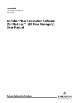
Figure 1-1. FloBoss 503 Flow Manager
Mounting Flange
LCD
Cove
r
Operato
r
Interface (LOI)
Connecto
r
Sensor

FloBoss 503 and 504 Instruction Manual
1-4 General Information Rev 04/04
Figure 1-2. FloBoss 504 Flow Manager
1.3.1 Hardware
The Main Electronics Board mounts on quick-fastener stand-offs located on top of the swing-out panel.
The majority of the components are surface-mounted with only the top side of the board used for
components. The Main Electronics Board has built-in I/O capabilities, an LCD display, provisions for
an optional communications card, and provisions for an optional I/O card. For more information on the
Main Electronics Board, refer to Section 1.5.1, Main Electronics Board Overview, on page 1-13.
A Motorola 32-bit Complementary Metal-Oxide Semiconductor (CMOS) microprocessor runs at 14.7
MHz and has low-power operating modes, including inactivity and low battery conditions. The
FloBoss comes standard with 512 KB of built-in, super capacitor-backed Static Random Access
Memory (SRAM) for storing data and history. The FloBoss also has 512 KB of programmable Read-
Only Memory (flash ROM) for storing operating system firmware, applications firmware, and
configuration parameters.
The built-in inputs and outputs (I/O) on the FloBoss consist of a port for a Sensor, a 4-wire Resistance
Temperature Detector (RTD) input interface, and a Discrete Output (DO). Three diagnostic Analog
Inputs are dedicated to monitoring battery voltage, charger voltage, and enclosure/battery temperature.
Refer to Section 1.5, Product Electronics, on page 1-13 for more information.
Mounting Flange
Operato
r
Interface (LOI)
Connecto
r
Sensor
LCD
Cove
r

FloBoss 503 and 504 Instruction Manual
Rev 04/04 General Information 1-5
On the FloBoss 503, the orifice-metering Sensors measure differential pressure and static pressure
(absolute or gauge) by converting the applied pressure to electrical signals and making the readings
available to the Main Electronics Board. The Sensor housing fastens to a flanged adapter, which in
turn mounts with four bolts to the bottom of the enclosure. The Sensor cable plugs directly into the
Main Electronics Board. For more information on the Sensor for the FloBoss 503, refer to Section 6.
On the FloBoss 504, the turbine-metering Sensor Module (SM) measures pulses and static pressure by
electronically counting pulses and converting the applied pressure to electrical signals. It makes the
readings available to the Main Electronics Board. The Sensor Module housing mounts with four bolts
to the bottom of the enclosure. The Sensor Module cable plugs directly into the Main Electronics
Board. For more information on the Sensor Module for the FloBoss 504, refer to Section 7.
The I/O parameters, sensor inputs, flow calculations, power control, security, and FST programm-
ability are configured and accessed using the ROCLINK for Windows software. Refer to the
ROCLINK for Windows Configuration Software User Manual (Form A6091), for details concerning
software capabilities.
1.3.2 Options and Accessories
The FloBoss supports the following options and accessories:
♦ Communications Card for host communications (Comm1).
♦ Bracket for internally-mounted radio.
♦ I/O Card (10-channel or 24-channel).
♦ Internal AC Power Supply.
♦ Intrusion Switch.
♦ Local Operator Interface (LOI) cable.
♦ Batteries.
♦ Solar Panels.
A variety of plug-in communication cards are available that allow you to customize the FloBoss
installation for most communications requirements. The communication cards provide an interface
for the host communications port (Comm1). These cards permit serial communication protocols, as
well as dial-up modem communications. Refer to Section 4, Communications Installation and wiring,
for more information.
A radio with an integral modem can also be mounted inside the FloBoss enclosure using the optional
radio bracket. Refer to Section 2, Installation and Use. The radio bracket allows a radio up to 57.15
mm (2.25 inches) high to be mounted securely in the battery compartment inside the FloBoss
enclosure. Power for the radio can be controlled through the EIA-232 (RS-232) communications card.
Clearance is provided for the radio antenna cable to exit through the bottom of the enclosure.

FloBoss 503 and 504 Instruction Manual
1-6 General Information Rev 04/04
An optional FloBoss 500-series I/O Cards provide additional inputs and outputs for expanded
monitoring and control applications. The I/O Card contains Analog Inputs (AI), an Analog Output
(AO), Discrete Inputs (DI), Pulse Inputs (PI) and Discrete Outputs (DO). The DI, DO, and PI
circuitry is optically coupled to help isolate the processor board from the input signal. Refer to
Section 4, Communications Installation and Wiring, for more information.
An internal AC power supply is available as a factory-installed option. The AC power supply
converts AC line power to DC power for use with the FloBoss and the associated accessories. The
power supply typically is used in line-powered installations. If battery backup is used in the line-
powered installation, the AC supply also functions as a battery charger. The unit provides a fully-
regulated, temperature-compensated output that is protected from overcurrent conditions. The AC
supply is factory-installed in the battery compartment of the FloBoss. Refer to Section 3, Power
Connections, for details concerning the AC power supply.
The intrusion switch acts as a tamper detector for the FloBoss units. The intrusion switch is a
momentary contact switch used to detect whether the door to the enclosure is open or closed. The
switch, which has a normally-closed contact, is designed to be mounted in the FloBoss enclosure.
Refer to the ROC/FloBoss Accessories Instruction Manual (Form A4637) for details. An I/O Card
must be installed in order to use the intrusion switch. The status of the switch can be configured to
generate an alarm when the door to the enclosure is open. Refer to Section 5, Inputs and Outputs, for
details.
The FloBoss enclosure can hold up to four sealed lead-acid batteries. The 12-volt batteries provide
approximately 7 Amp-hours each, resulting in up to 28 Amp-hours of backup capacity or up to 21
Amp-hours of backup capacity when used with an AC power supply. The batteries are mounted under
the electronics swing-out panel and are retained by the panel when it is secured. The batteries are
connected to a wiring harness that allows the batteries to be changed without removing power from
the unit. Refer to Section 2, Power Connections, for further details.
A solar panel can be installed to recharge the backup batteries; it connects to the POWER charge
inputs on the Main Electronics Board. Circuitry on the Main Electronics Board monitors and
regulates the charge based on battery voltage, charging voltage, and temperature. The typical panels
used are 12-volt panels with output ratings of 5 or 10 watts. The panels are typically bracket-mounted
on a pole or pipe, and the wiring is brought into the bottom of the FloBoss enclosure through a liquid-
tight fitting. Refer to Section 3, Power Connections, for further details.

FloBoss 503 and 504 Instruction Manual
Rev 04/04 General Information 1-7
1.4 PRODUCT FUNCTIONS
This section describes the functions of the FloBoss 503 and FloBoss 504, most of which is determined
by firmware. The features and applications provided by the firmware must be configured with
ROCLINK for Windows software.
1.4.1 Firmware
The firmware, contained in flash ROM on the electronics board, determines much of the functionality
of the FloBoss, such as:
♦ Memory logging of 240 alarms and 240 events.
♦ Archival of data for up to 15 history points for up to 35 days.
♦ AGA flow calculations.
♦ Power cycling control.
♦ Flow calculations for a single meter run.
♦ Logic and sequencing control by means of two user-defined Function Sequence Tables (FST).
♦ Closed-loop (PID) control.
♦ Communications based on either ROC protocol or Modbus protocol (slave mode only).
♦ Spontaneous Report by Exception (SRBX) communication to a host computer.
♦ User level security.
1.4.2 Flow Measurement
The primary function of the FloBoss 503 is to measure the flow of natural gas through an orifice in
accordance with the 1992 American Petroleum Institute (API) and American Gas Association (AGA)
standards.
The primary inputs used for the orifice metering flow measurement function are differential pressure,
static pressure, and temperature. The differential and static pressure inputs, which are sampled once
per second, come from a Dual-Variable Sensor (DVS) or a Multi-Variable Sensor (MVS). The
temperature input, which is sampled and linearized once per second, comes from an Resistance
Temperature Detector (RTD) probe.
The primary function of the FloBoss 504 is to measure the flow of gas using a turbine meter (with a
single or dual pulse train), in accordance with the American Gas Association (AGA), American
Petroleum Institute (API), and International Standards Organization (ISO) standards.
The primary inputs used for turbine flow measurement are Pulse Input (PI) counts, static (line)
pressure, and temperature. The PI counts are acquired from a turbine meter, the static pressure
(including auxiliary pressure) input comes directly from the Sensor Module, and the temperature input
is read directly by the FloBoss unit from an RTD probe.

FloBoss 503 and 504 Instruction Manual
1-8 General Information Rev 04/04
1.4.2.1 1992 Flow Calculations for Orifice Metering
The 1992 flow calculation is in accordance with ANSI/API 2530-92 (AGA Report No. 3 1992), API
Chapter 14.2 (AGA Report No. 8 1992 2nd printing 1994), and API Chapter 21.1. The 1992 flow
calculation may be configured for either Metric or US units.
Flow Time
The differential pressure stored for each second is compared to the configured low flow cutoff. If the
differential pressure is less than or equal to the low flow cutoff or the converted static pressure is less
than or equal to zero, flow is considered to be zero for that second. Flow time for a recalculation
period is defined to be the number of seconds for which the differential pressure exceeded the low
flow cutoff.
Input and Extension Calculation
Every second the FloBoss unit stores the measured input for differential pressure, static pressure, and
temperature and calculates the flow extension (defined as the square root of the absolute upstream
static pressure times the differential pressure).
Flow time averages of the inputs and the flow extension over the configured recalculation period are
calculated, unless there is no flow for an entire recalculation period. Averages of the inputs are
recorded to allow monitoring during no flow periods.
Instantaneous Rate Calculations
The instantaneous value of the flow extension is used with the previous recalculation period’s Integral
Multiplier Value (IMV), C Prime (C') for orifice, and Base Multiplier Value (BMV) for turbine
metering, to compute the instantaneous flow rate. The IMV is defined as the value resulting from the
calculation of all other factors of the flow rate equation not included in the Integral Value (IV). The
IV is defined as the flow extension. The instantaneous flow rate is used with the volumetric heating
value to compute the instantaneous energy rate.
Flow and Energy Accumulation
The averages of the differential and static pressure, temperature, and flow extension are used with the
flow time to compute the flow and energy over the recalculation period. The flow and energy are then
accumulated and stored at the top of every hour. At the configured contract hour, the flow and energy
are then stored to the Daily Historical Log and zeroed for the start of a new day.

FloBoss 503 and 504 Instruction Manual
Rev 04/04 General Information 1-9
1.4.2.2 Flow Calculations for Turbine Metering
The turbine flow calculation is in accordance both with 1996 AGA Report No. 7 (1993 API Chapter
21.1) and with ISO 9951-1993(E). The FloBoss 504 performs 1992 AGA8 compressibility calculations
in accordance with AGA Report No. 8 1992 (API Chapter 14.2); for ISO calculations, the FloBoss 504
performs ISO 12213-2 compressibility. The flow calculation may be configured to use either Metric or
US units. Pulse fidelity/integrity checking at Level A through Level E is also performed according to
AGA/API 5-5 and ISO 6551-1982(E). These integrity levels are summarized as follows:
♦ Level A – This is the highest level of integrity; it provides continuous protection against errors.
Both verification and correction are performed by comparing two pulse streams from the
turbine. The two pulse streams are checked against each other to produce a corrected pulse
stream, which is then used in the flow calculation. Errors are indicated even when corrected.
For Level A, the FloBoss 504 employs a patent-pending algorithm and requires a high-
precision turbine with no more than 1% phase error between blades.
♦ Level B – This level provides continuous warning of errors by comparing two pulse streams
from the turbine against each other. For Level B, the FloBoss 504 employs a patent-pending
algorithm.
♦ Level C – This level provides automatic warning of errors at specified intervals by comparing
two pulse streams from the turbine against each other and requires a turbine with no more than
15% phase error between blades.
♦ Level D – This level provides manual warning of errors at specified intervals by comparing
the results of one pulse stream from the turbine visually against another means of
measurement, such as a mechanical meter.
♦ Level E – This is the lowest level of integrity; it provides no detection of errors by comparison
of the one pulse stream from the turbine to any other results, but instead depends entirely on
the quality of the installed equipment.
After power-up, the Master Controller Unit (MCU) enters the normal operation mode. The Sensor
Module (SM) then counts the pulses as they occur. Once every 992 ms, the SM reports to the MCU
the number of pulses received by its pulse inputs, as well as the static and auxiliary pressures. The
values are stored in temporary memory.
Once every Scan Period, the MCU processes the pulse counts, determines the number of pulse counts
since the last reading, and calculates a rate. Next, the static pressure and auxiliary pressure values are
read. Then the temperature is read and linearizing compensation is applied to the pressure readings if
necessary. The RTD is internally re-calibrated for every 5°C (9°F) change as sensed by the enclosure
temperature diagnostic input.
All resultant values are stored in the current value database. The values are taken from the current
value database and used to calculate the Minute, Hour, and Daily historical values.
Finally, the MCU enters a low-power mode and waits for the beginning of the next cycle.
Once a minute and once an hour, the values are logged along with other configured values to the
Historical Database. At the configured Contract Hour, the values are stored to the Daily Historical
Log and zeroed for the start of a new day.

FloBoss 503 and 504 Instruction Manual
1-10 General Information Rev 04/04
1.4.3 History Points
A total of fifteen history points may be logged and accessed in the FloBoss unit. The first eight are
pre-configured for flow metering history and cannot be changed. Refer to Table 1-1.
Table 1-1. History Points
History
Point
Number
Value Archive Type
1 Flowing Minutes Today Accumulate
FloBoss 503 – Differential Pressure Average
2
FloBoss 504 – Raw pulse count from Pulse Input Primary Device Totalize
3 Static or Line Pressure Average
4 Temperature Average
FloBoss 503 – IMV, Integral Multiplier Value, or C Prime Average
5
FloBoss 504 – BMV, Base Multiplier Value, or C Prime Average
FloBoss 503 – Pressure Extension or IV, Integral Value Average
6
FloBoss 504 – Uncorrected Flow Today Accumulate
7 Instantaneous Flow Accumulate
8 Instantaneous Energy Accumulate
The Average Archive Type employs one of the following techniques:
♦ Flow dependent time-weighted linear averaging (default).
♦ Flow dependent time-weighted formulaic averaging.
♦ Flow-weighted linear averaging.
♦ Flow-weighted formulaic averaging.
The seven user-configurable history points and Averaging Technique may be configured in ROCLINK
for Windows software.
1.4.3.1 Minute Historical Log
The FloBoss unit has a 60-minute historical log for every history point. The Minute Historical Log
stores the last 60 minutes of data from the current minute. Each history point has Minute Historical
Log entries, unless the history point is configured for FST-controlled logging.
1.4.3.2 Hourly Historical Log
The FloBoss unit has a total of 840 hourly historical logs available for every history point. The
Hourly Historical Log is also called the Periodic Log. Normally, the Hourly Log is recorded every
hour at the top of the hour. The exceptions are FST Minute and FST Second logging.
The time stamp for periodic logging consists of the month, day, hour, and minute. The exception is
for FST Second logging, for which the time stamp consists of the day, hour, minute, and second.

FloBoss 503 and 504 Instruction Manual
Rev 04/04 General Information 1-11
1.4.3.3 Daily Historical Log
The FloBoss unit has a total of 35 daily historical logs for every history point. The Daily Log is
recorded at the configured contract hour every day with a time stamp that is the same as the Hourly
Log. Each history point has daily historical log entries, unless the history point is configured for FST-
controlled logging.
1.4.3.4 Alarm Log
The Alarm Log contains the change in the state of any alarm signal that has been enabled for alarms.
The system Alarm Log has the capacity to maintain and store up to 240 alarms in a circular log. The
Alarm Log has information fields which include time and date stamp, alarm clear or set indicator, and
either the tag name of the point which was alarmed with the current value or a 14-character ASCII
description.
In addition to providing functionality for appending new alarms to the Alarms Log, it allows host
packages to request the index of the most recently logged alarm entry. Alarm logging is available
internally to the system, to external host packages, and to FSTs. Alarm Logs are not stored to the flash
ROM during the Save Configuration function in ROCLINK for Windows software.
The Alarm Log operates in a circular fashion with new entries overwriting the oldest entry when the
buffer is full. The Alarm Log provides an audit history trail of past operation and changes. The Alarm
Log is stored separately to prevent recurring alarms from overwriting configuration audit data.
1.4.3.5 Event Log
The Event Log contains changes to any parameter within the FloBoss unit made through the protocol.
This Event Log also contains other FloBoss unit events, such as power cycles, cold starts, and disk
configuration downloads.
The system Event Log has the capacity to maintain and store up to 240 events in a circular log. The
Event Log has information fields, which include point type, parameter number, time and date stamp,
Point Number (if applicable), the operator identification, and either the previous and current parameter
values or a 14-byte detail string in ASCII format.
In addition to providing functionality for appending new events to the Events Log, it allows host
packages to request the index of the most recently logged event entry. Event logging is available
internally to the system, to external host packages, and to FSTs.
Event Logs are not stored to flash ROM when the Save Configuration function is issued in ROCLINK
for Windows software. The Event Log operates in a circular fashion with new entries overwriting the
oldest entry when the buffer is full. The Event Log provides an audit trail history of past operation
and changes. The Event Log is stored separately to prevent recurring alarms from overwriting
configuration audit data.

FloBoss 503 and 504 Instruction Manual
1-12 General Information Rev 04/04
1.4.4 Security
The FloBoss unit provides for security within the unit. A maximum of 16 log-on identifiers (Operator
IDs) may be stored. In order for the unit to communicate, the log-on ID supplied to the ROCLINK for
Windows software must match one of the IDs stored in the FloBoss unit. The Local Port (Security on
LOI) has security Enabled by default. The Host Port (Comm1) can likewise be configured to have
security protection, but is disabled by default. Refer to the ROCLINK for Windows Configuration
Software User Manual (Form A6091) concerning security.
1.4.5 Function Sequence Tables (FST)
The FloBoss unit supports FST user programmability. The two FST programs can be up to 4000 bytes
each (typically 200 or 300 lines of code). The FST code resides in static Random Access Memory
(RAM) and is backed up to flash memory when the Save Configuration function is issued through
ROCLINK for Windows software. Refer to the ROCLINK for Windows Configuration Software User
Manual (Form A6091).
1.4.6 Modbus
The Modbus Protocol Emulation Program is contained within the FloBoss firmware. The Modbus
application is designed to allow the FloBoss unit to emulate on the Host Port (Comm1) the
communications protocol used by Modbus devices. The Modbus communications protocol is fully
described in the reference guide entitled “Modicon Modbus Protocol Reference Manual” publication
PI-MBUS-300 (not available from Emerson Process Management).
The Modbus protocol supports two modes of transmission: American Standard Code for Information
Interchange (ASCII) and Remote Terminal Unit (RTU), with RTU as the default. Both modes of
transmission are supported by the FloBoss unit. In addition, a version of Modbus with EFM
extensions can be emulated as a slave device. Refer to the ROCLINK for Windows Configuration
Software User Manual (Form A6091) for details.
1.4.7 Power Control
The Power Control function is used with the EIA-232 (RS-232) communications card to provide power
savings when using a radio or cell phone for communications. Two modes of Power Control are
possible: Second and Minute. In Second mode, the time base for the timers is in 100 millisecond
increments and is primarily used with radios. In Minute mode, the time base for the timers is in 1
minute increments that are kept in tune with the Real-Time Clock and is primarily used with cell phones.
Three cycling zones are provided, but zones can be disabled as desired. The EIA-232 (RS-232) card
provides the switching mechanism and is controlled by the Data Terminal Ready (DTR) signal.
The Power Control function calculates which zone should be currently active. In Second mode, the
Power Control begins in the ON state and continues with a full On Time and then goes to the OFF
state for the full Off Time. In Minute mode, the Power Control determines if it should be ON or OFF
and how much time it needs until it switches. Refer to Section 3, Power Connections and Section 4,
Communications Installation and Wiring.

FloBoss 503 and 504 Instruction Manual
Rev 04/04 General Information 1-13
1.4.8 PID Control
The Proportional, Integral, and Derivative (PID) Control functionality calculates both the Primary
Control and Override Control change in output. It then selects which Control is to be used, based
upon whether the High Override Type Select or Low Override Type Select is chosen and adjusts the
Output control as necessary. PID Control can only be active if an I/O card is installed in the FloBoss
unit. The Output of the PID functions can be implemented either through an Analog Output or
through a pair of Discrete Outputs for open/close control.
1.4.9 Spontaneous Report By Exception (SRBX) Alarming
The SRBX functionality allows a communications port to be set up to enable the FloBoss unit to
contact the host computer when specified alarm conditions exist. The host will be sent a message that
an alarm condition exists.
1.5 PRODUCT ELECTRONICS
This section describes the FloBoss Main Electronics Board. For calculating power and connecting to
wiring, refer to Section 3, Power Connections. For Communications Installation and Wiring, refer to
Section 4. For I/O Cards, refer to Section 5, Inputs and Outputs. For the Flow Sensors, refer to
Section 6 (FloBoss 503) or Section 7 (FloBoss 504).
1.5.1 Main Electronics Board Overview
The Main Electronics Board components support the functionality of the FloBoss. Refer to Figure
1-3. The board provides: 32-bit microprocessor; built-in static RAM; Flash ROM; Liquid Crystal
Display (LCD) display; communications card Host Port; Local Port (LOI); built-in Discrete Output
(DO); RTD input; diagnostic monitoring; Real-Time Clock and backup power; automatic self tests;
and power regulation modes.
1.5.2 Microprocessor and Memory
The FloBoss unit derives processing power from a 32-bit microprocessor. The 32-bit CMOS micro-
processor features dual 32-bit internal data buses and a single 8-bit external data bus. The unit can
address up to 4 MB of memory including high-speed direct memory access.
The Main Electronics Board has 512 KB of static random access memory (SRAM) for storing
interrupt vectors, Function Sequence Tables (FST), alarms, events, and history data.
The Main Electronics Board also has a 512 KB flash memory chip for storing the operating system
factory code and configuration parameters. Two of the 64 KB blocks are reserved for internal usage.

FloBoss 503 and 504 Instruction Manual
1-14 General Information Rev 04/04
1.5.3 Liquid Crystal Display (LCD)
A two-line Liquid Crystal Display (LCD) panel is factory-mounted directly to the Main Electronics
Board and visible through the window on the front panel. The panel has automatic contrast
adjustment, due to temperature sensing and bias adjustment circuitry on the Main Electronics Board.
The LCD panel remains on at all times when the power applied is in the valid operating range.
The built-in LCD provides the ability to look at data and configuration parameters while on site
without using the Local Port (LOI) and a PC. Through this display, you can view predetermined
information stored in the FloBoss. Up to 16 items can be defined for display. The LCD automatically
cycles through the configured list of items displaying a new value approximately every three seconds.
The first two displays, which cannot be configured by the user, show values for time and date,
operating voltages, and battery condition. The next five displays are configured by the factory to
show certain flow parameters, but you may change their configuration. Refer to the ROCLINK for
Windows Configuration Software User Manual (Form A6091) for details on how to configure the list
of values for the LCD panel.

FloBoss 503 and 504 Instruction Manual
Rev 04/04 General Information 1-15
P3
J1
RST
NORM
P5
POWER
+BAT-
-
P/DP
+
RADIO
+CHG-
-
BLK REDWHT
LOI
+
DO
REF
-
RTD
+
RTS
RET
P8
P9
P11
P10
FL1
PT2
CR6
PT3
CR7
PT1
CR9
MV1
MV2
U12
U11
U8
FLASH
U7
PROCESSOR
68LC302
RTD
A/D
CLOCK
U6
U9
SRAM
C3
DOC0331B
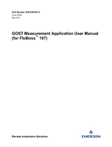
Figure 1-3. Main Electronics Board
Reset
Jumper (P1)
Comm Card
Connector
Supe
r
Capacito
r
"Battery"
Power Wiring
Terminal Block
Built-in I/O
Terminal Blocks
Sensor Connecto
r
I/O Card
Connecto
r
Liquid Crystal
Display (LCD)

FloBoss 503 and 504 Instruction Manual
1-16 General Information Rev 04/04
1.5.4 Communications Ports
The FloBoss unit provides two communication ports:
♦ Local Operator Interface Port (LOI) – Local Port.
♦ Host Port for communication to a remote host – Comm1 Port.
1.5.4.1 Local Port – LOI
The Local Port (LOI) provides direct communications between the FloBoss unit and the serial port of
an operator interface device, such as a PC. The interface allows you to access the FloBoss unit (using
ROCLINK for Windows software) for configuration and transfer of stored data. The LOI terminal
plus the Ready to Send (RTS) terminal on the Main Electronics Board provide wiring access to a
built-in EIA-232 (RS-232) serial interface, which is capable of 19,200 bps operation. The Local Port
supports only ROC protocol communications. The LOI also supports the log-on security feature of
the FloBoss unit if the Security on LOI is Enabled in ROCLINK for Windows software.
NOTE: The following installation should not be used in Class 1, Division 2 hazardous
(C1D2) areas.
A cannon-type waterproof connector on the bottom of the enclosure provides connection through a
prefabricated cable for a Local Port device, typically a personal computer (PC) running ROCLINK for
Windows software. Inside the FloBoss enclosure, the cannon-type connector is wired to three
terminals (LOI) on the Main Electronics Board.
1.5.4.2 Host Port – Comm1
The Host Port (Comm1) is activated by the installation of the optional communications card. The
Host Port is used to monitor or alter the FloBoss unit from a remote site using a host or ROCLINK for
Windows software. The Host Port automatically configures itself based upon the specific
communications card installed. The Host Port supports rates up to 19,200 bps. Comm1 also supports
the log-on security feature of the FloBoss unit if the Security on Comm1 is Enabled in ROCLINK for
Windows software.
One of the following card types can be accommodated:
♦ EIA-232 (RS-232) for asynchronous serial communications.
♦ EIA-485 (RS-485) for asynchronous serial communications.
♦ Dial-up modem for communications over a telephone network.
The Host Port can receive messages in either ROC or Modbus protocol and responds using the same
protocol in which the message was received. The Host Port is capable of initiating a message in
support of Spontaneous Report by Exception (SRBX) and Store and Forward when using ROC
protocol. Refer to the ROCLINK for Windows Configuration Software User Manual (Form A6091).
/