Page is loading ...

PRECISION DIGITAL CORPORATION
233 South Street • Hopkinton MA 01748 USA
Tel (800) 343-1001 • Fax (508) 655-8990
www.predig.com
ConsoliDator
®
Multi-Channel Controller
Instruction Manual
ConsoliDator 8 ConsoliDator 4
Eight 4-20 mA Inputs Four 4-20 mA Inputs
Eight 24 VDC @ 20 mA Four 24 VDC @ 20 mA
Two 4-20 mA Outputs Four 4-20 mA Outputs
Features and Highlights
Nine Form C 10 A Relays Powered from AC or DC
Four Pulse Inputs 32-Point Linearization
Four Digital Inputs RS-232 Modbus
®
RTU
Panel or wall mount Square Root Function
Sum and Difference
Functions
FREE Programming &
data logging software
PC
Software
Included!

ConsoliDator Multi-Channel Controlle
r
Instruction Manual
2
Visit our Web Site
http://www.predig.com/
Disclaimer
The information contained in this document is subject to change without notice. Precision
Digital Corporation makes no representations or warranties with respect to the contents
hereof, and specifically disclaims any implied warranties of merchantability or fitness for a
particular purpose.
All trademarks mentioned in this document are the property of their respective owners.
Copyright © 2009-2017 Precision Digital Corporation
This document contains ratings and requirements necessary for proper installation.
Distribution of modified versions is strictly prohibited. Any text, chart, diagram, or table
reproduced must be reproduced in its entirety without alteration.

ConsoliDator Multi-Channel Controlle
r
Instruction Manual
3
INTRODUCTION
The ConsoliDator is an easy to use multiple-channel controller. It accepts 4-20 mA inputs,
flow meter pulse inputs, and digital inputs. It is equipped with multiple relays, which all have
user-definable actions, 4-20 mA outputs, and Modbus protocol communication capabilities.
ORDERING INFORMATION
ConsoliDator Controllers
Model Mounting
4-20
Inputs
Pulse
Inputs
4-20
Outputs
Relays
PD980-8K9-15 Wall
8 4 2 9
PD981-8K9-15 Panel
PD940-8K9-15 Wall
4 4 4 9
PD941-8K9-15 Panel
Accessories
Model Description
PDA2901 NEMA 4X Enclosure for PD981 or PD941 models.
PDA2904 NEMA 4X Large Enclosure for PD981 or PD941 models.
PDP2901 Sub Panel with Terminal Strips for PDA2901 Enclosure.
PDP2902 Low-Cost Sub Panel without Terminal Strips for PDA2901.
PDP2904 Sub Panel with Terminal Strips for PDA2904 Enclosure.
PDP2905 Low-Cost Sub Panel without Terminal Strips for PDA2904.
PDA6901 2" Pipe Mounting Kit for PDA2901 Enclosure.
PDA6902 2" Pipe Mounting Kit for PDA2904 Enclosure.
PDX6901 Snubber .01µF, 470Ω, Flexible Leads.
PDA7485-I RS-232 to RS422/485 Isolated Converte
r
PDA7485-N RS-232 to RS422/485 Non-Isolated Converter
PDA8232-N USB to RS-232 Converte
r
PDA8485-I USB to RS422/485 Isolated Converter
PDA8485-N USB to RS422/485 Non-Isolated Converte
r
PDA9232-01 ConsoliDator Null Modem Cable
PDA9232-02 RS-232 Computer Cable
Setup & Programming Services
Part Number Description
PDN-CSETUP2 Custom Setup & Programming
PDN-CERTCAL Certificate of Calibration
PDN-CERTCAL2 Certificate of Calibration with Data
J
1
INPUT
J2
OUTPUT
J3
INPUT
J4
INPUT
J5
RELAY
J7
POWER
J6
RELAY
J8
RELAY
NO NCC
RELAY 1
NO NCC
RELAY 2
NO NCC
RELAY 3
NO NCC
RELAY 4
NO NCC
RELAY 9
GND HN
A
C POWER
A
NALOG 1
A
NALOG 2
A
NALOG 3
A
NALOG 4
GND/
RET
A
NALOG 5/
FLOW 1
+
-
GND/
RET
+
-
GND/
RET
+
-
GND/
RET
+
-
A
NALOG 6/
FLOW 2
A
NALOG 7/
FLOW 3
A
NALOG 8/
FLOW 4
COMMON
INTERNAL
POWER
G
N
D
+
2
4
L
O
O
P
I
N
L
O
O
P
O
U
T
L
O
O
P
I
N
L
O
O
P
O
U
T
L
O
O
P
O
U
T
L
O
O
P
I
N
+
2
4
L
O
O
P
O
U
T
G
N
D
L
O
O
P
I
N
EXTERNAL KEYPAD
K
E
Y
4
K
E
Y
3
K
E
Y
5
K
E
Y
2
K
E
Y
1
NO NCC
RELAY 5
NO NCC
RELAY 6
NO NCC
RELAY 7
NO NCC
RELAY 8
DIGITAL INPUTS
+
I
N
P
U
T
2
+
I
N
P
U
T
1
ANALOG
OUTPUT 1
ANALOG
OUTPUT 2
ANALOG
OUTPUT 3
ANALOG
OUTPUT 4
COMMON
INTERNAL
POWER
C
O
M
M
O
N
+
I
N
P
U
T
3
+
I
N
P
U
T
4
GG
GND
+
DC POWER
GND/
RET
+
-
GND/
RET
+
-
GND/
RET
+
-
GND/
RET
+
-
Model: PDP2901
Sub Panel for PDA2901 Enc
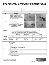
PDA2901
Optional enclosure features quick-release
latches, a hinged front panel and internal space
for mounting additional components such as
relays and switches.
PDP2901
Optional sub panel features terminal
strips for convenient installation of all
power, analog, and relay lines using up
to 8 AWG wire.

ConsoliDator Multi-Channel Controlle
r
Instruction Manual
4
TABLE OF CONTENTS
INTRODUCTION ----------------------------------------------------------------------- 3
ORDERING INFORMATION -------------------------------------------------------- 3
TABLE OF CONTENTS -------------------------------------------------------------- 4
SPECIFICATIONS --------------------------------------------------------------------- 7
General ------------------------------------------------------------------------------------------- 7
4-20 mA Analog Inputs --------------------------------------------------------------------- 8
Flow Meter Pulse Inputs -------------------------------------------------------------------- 8
Digital Inputs ----------------------------------------------------------------------------------- 8
Relays -------------------------------------------------------------------------------------------- 9
4-20 mA Transmitter Outputs ----------------------------------------------------------- 10
Modbus
®
Serial Communications ----------------------------------------------------- 10
ConsoliDator
®
Software ------------------------------------------------------------------ 10
SAFETY INFORMATION ---------------------------------------------------------- 11
INSTALLATION ---------------------------------------------------------------------- 12
Unpacking ------------------------------------------------------------------------------------- 12
Wall Mounting ------------------------------------------------------------------------------- 12
Panel Mounting ------------------------------------------------------------------------------ 13
Connections ---------------------------------------------------------------------------------- 14
Power Connections ---------------------------------------------------------------------- 14
Input Signal Connections --------------------------------------------------------------- 15
4-20 mA Analog Input Connections ---------------------------------------------- 15
Flow Meter Pulse Input Connections --------------------------------------------- 16
Digital Input Connections ----------------------------------------------------------- 16
Analog Output Connections ------------------------------------------------------------ 17
Note: All inputs and outputs share a common ground. DO NOT power
inputs and outputs with the same power supply.Relay Connections -------- 17
Switching Inductive Loads ---------------------------------------------------------- 18
Serial Communication Connections ------------------------------------------------- 19
Serial Communication Using RS-422/485 -------------------------------------- 19
External Keypad Connections --------------------------------------------------------- 19
NAVIGATING AND EDITING ----------------------------------------------------- 20
SETUP AND PROGRAMMING -------------------------------------------------- 21
Main Setup Menu --------------------------------------------------------------------------- 22
General Functions ------------------------------------------------------------------------ 22
Buzzer ----------------------------------------------------------------------------------- 22
Time Out -------------------------------------------------------------------------------- 22
Password -------------------------------------------------------------------------------- 22
Backlight --------------------------------------------------------------------------------- 23
Baud Rate ------------------------------------------------------------------------------- 23
Parity ------------------------------------------------------------------------------------- 23
Modbus ID ------------------------------------------------------------------------------ 23
Tx Delay --------------------------------------------------------------------------------- 23
Configuring 4-20 mA Inputs ------------------------------------------------------------- 24

ConsoliDator Multi-Channel Controlle
r
Instruction Manual
5
Display Preferences --------------------------------------------------------------------- 24
Decimal Point -------------------------------------------------------------------------- 24
Units -------------------------------------------------------------------------------------- 24
Bargraph -------------------------------------------------------------------------------- 24
Input Scaling & Math Functions ------------------------------------------------------- 25
Linear ------------------------------------------------------------------------------------ 25
Square Root ---------------------------------------------------------------------------- 26
Exponent -------------------------------------------------------------------------------- 27
Integration Mode ---------------------------------------------------------------------- 28
Fixed Value ----------------------------------------------------------------------------- 28
Summation & Difference ------------------------------------------------------------ 28
Multi-Point Linearization ------------------------------------------------------------- 29
Sensor Input Setup ----------------------------------------------------------------------- 29
Setting Flow Meter Pulse Inputs ------------------------------------------------------- 30
Display Parameters ---------------------------------------------------------------------- 30
Input Configuration Parameters ------------------------------------------------------- 30
Programming Relays ---------------------------------------------------------------------- 31
Supervisory or Summary Alarm Modes --------------------------------------------- 31
High or Low Alarm Modes -------------------------------------------------------------- 31
Multi-Channel High or Low Alarm Modes ------------------------------------------ 32
High or Low Pulse Alarm Modes ----------------------------------------------------- 33
Trigger Alarm Mode ---------------------------------------------------------------------- 34
Annunciator High or Low Alarm Modes --------------------------------------------- 34
Plunger Lift by Differential Pressure Mode ----------------------------------------- 35
Plunger Lift by Time Mode ------------------------------------------------------------- 35
Lead-Lag Modes (Pump Alternation Control) ------------------------------------- 36
Linear Pulse Width Modulation Mode ----------------------------------------------- 38
Proportional Plus Integral Pulse Width Modulation Mode ---------------------- 39
Setting 4-20 mA Outputs ----------------------------------------------------------------- 40
Linear Scaling of 4-20 mA Output ---------------------------------------------------- 40
PID Control Using 4-20 mA Output -------------------------------------------------- 40
OPERATION -------------------------------------------------------------------------- 41
Manual and Simulation Modes --------------------------------------------------------- 45
Contrast Adjustment Control ----------------------------------------------------------- 46
MODBUS
®
SERIAL COMMUNICATION --------------------------------------- 46
Modbus Register Tables ----------------------------------------------------------------- 47
CONSOLIDATOR MONITOR SOFTWARE ----------------------------------- 52
Connecting to PC --------------------------------------------------------------------------- 52
Installing Software ------------------------------------------------------------------------- 52
Using ConsoliDator Monitor Software ----------------------------------------------- 52
Data Logging ------------------------------------------------------------------------------ 53
Programming Through Software ------------------------------------------------------ 53
OVERALL DIMENSIONS ---------------------------------------------------------- 54
TROUBLESHOOTING TIPS ------------------------------------------------------ 55

ConsoliDator Multi-Channel Controlle
r
Instruction Manual
6
Table of Figures
Figure 1. Wall Mount Dimensions (PD980 & PD940) ..................................... 12
Figure 2. Panel Mount Dimensions (PD981 & PD941) ................................... 13
Figure 3. Power Connections .......................................................................... 14
Figure 4. Transmitter Powered by Ext. Supply or Self-Powered .................. 15
Figure 5. Transmitters Powered by ConsoliDator ......................................... 15
Figure 6. Three-Wire Transmitters Powered Externally ................................ 15
Figure 7. Flow Meter Pulse Input Connections .............................................. 16
Figure 8. Digital Input From Switch Closure .................................................. 16
Figure 9. Digital Input From Live Signal ......................................................... 16
Figure 10. 4-20 mA Output Powered by ConsoliDator .................................. 17
Figure 11. 4-20 mA Output Powered by External Supply .............................. 17
Figure 12. Relay Connections ......................................................................... 18
Figure 13. AC and DC Loads Protection ......................................................... 18
Figure 14. Low Voltage DC Loads Protection ................................................ 18
Figure 15. Serial Connections ......................................................................... 19
Figure 16. External Keypad Connections ....................................................... 20
Figure 17. Linear Response Graph ................................................................. 25
Figure 18. Square Root Response Graph ....................................................... 26
Figure 19. Exponent Response Graph............................................................ 27
Figure 20. Pulse Relay Timing Diagram ......................................................... 33
Figure 21. Linear PWM Relay Timing Example .............................................. 38
Figure 22. PD980 & PD940 Overall Dimensions ............................................. 54
Figure 23. PD981 & PD941 Overall Dimensions ............................................. 54

ConsoliDator Multi-Channel Controlle
r
Instruction Manual
7
SPECIFICATIONS
Except where noted all specifications apply to operation at +25°C (77°F.)
General
DISPLAY Graphical: 4.75" x 3.5" (121 mm x 89 mm) LCD with backlight
320 X 240 pixels; Bargraph: Twenty divisions; Numerical: ±999999 or
99’ 11.9” (feet and inches)
DISPLAY UPDATE
RATE
1 every 2 seconds
PROGRAMMING
METHOD
Front panel buttons, external buttons, PC with ConsoliDator software,
or Modbus registers.
CALIBRATION All ranges are calibrated at the factory.
PASSWORD Programmable password restricts modification of programmed
settings and use of manual control functions.
NON-VOLATILE
MEMORY
Settings stored for a minimum of 10 years.
POWER AC: 90-264 VAC, 47 to 63 Hz, 20 VA
DC: 8-30 VDC, 15 W
FUSE AC: Unit is protected internally. 5 A max, slow blow, 250 V min UL
Recognized external fuse recommended.
DC: 5 A max, slow blow, 250 V (or 50 V min) UL Recognized
external fuse recommended.
ISOLATION &
GROUNDING
AC power is isolated from all inputs, outputs and relays to 1500 VAC.
Isolation to 500 VAC between analog inputs and analog outputs
requires powering analog outputs with external supply.
Signal and output power grounds are connected to earth (chassis)
ground. DC Power not isolated.
ENVIRONMENTAL Operating temperature range: 0 to 50°C (32 to 122°F)
Storage temperature range: -40 to 60°C (-40 to 140°F)
Relative humidity: 0 to 90% non-condensing
*All functions operate down to -10°C (14°F.) LCD response is slower
below 0°C (32°F) and may need contrast adjustment to be readable.
CONNECTIONS Removable screw terminal blocks accept 12 to 24 AWG wire.
DB9 male for serial connection.
TIGHTENING
TORQUE
Screw terminal connectors: 5 lb-in (0.56 Nm)
ENCLOSURE Type 1; Powder-coated steel; Color: warm gray
MOUNTING Wall Mount (PD980 & PD940): four screws/bolts
Panel Mount (PD981 & PD941): four screws/bolts
Cutout: 7.37" x 8.35" (187 mm x 212 mm)
OVERALL
DIMENSIONS
Wall Mount 8.75" x 8.00" x 3.00" (222 mm x 203 mm x 76 mm)
(H x W x D)
Panel Mount 8.66" x 9.36" x 3.10" (220 mm x 238 mm x 79 mm)
(H x W x D)
WEIGHT 5.5 lb (2.5 kg)
WARRANTY
1 year parts and labor
EXTENDED
WARRANTY
1 or 2 years, refer to Price List for details

ConsoliDator Multi-Channel Controlle
r
Instruction Manual
8
4-20 mA Analog Inputs
INPUT 4-20 mA; minimum span of 1 mA
ACCURACY
±0.03% of span 1 count
TEMPERATURE DRIFT
50 PPM/C from 0 to 50°C ambient
INPUT FUNCTION Linear, Square Root, Programmable Exponent, Multi-Point
(up to 32), or Fixed Value
MATH FUNCTION Sum or difference of 2 or more channels.
TOTALIZER Calculates total based on rate and time base of second,
minute, hour, or day; stored in non-volatile memory every 5
minutes; supports linear inputs only.
TOTALIZER RESET Via front panel buttons (password restricted)
DECIMAL POINT User selectable zero to six places with automatic overflow.
INPUT RANGE 4-20 mA, Minimum span of 1 mA
INPUT IMPEDANCE
130
NORMAL MODE
REJECTION
Greater than 100 dB at 50/60 Hz.
TRANSMITTER POWER
SUPPLY
Each input is equipped with +24 VDC current limited to
40 mA. External supply may be substituted.
ENGINEERING UNITS User selectable units or custom-entered units.
Flow Meter Pulse Inputs
ACCURACY ±1 count for K-Factor > 1
SIGNAL RANGE 100 mVp-p to 15 Vp-p; 1 Hz to 10 kHz
K-FACTOR Programmable from 0.00001 to 999999 pulses/unit
DISPLAY OPTIONS Rate and total values displayed on screen.
Bargraphs user selectable to indicate either total or rate.
ENGINEERING UNITS Show Total/Rate combinations:
GAL & GPS, GAL & GPM, GAL & GPH, GAL & GPD, MG &
MGD, BBL & BPH, BBL & BPD, LTR & LPs, LTR & LPM,
LTR & LPH, LTR & LPD, CF & CFS, CF & CFM, CF &
CFH, CF & CFD, MCF & MCD.
RATE & TOTAL
DECIMAL POINT
Independent and user selectable from zero to six places
with automatic overflow.
TOTALIZER Calculates total based on rate. Reading stored in non-
volatile memory every 5 minutes for power-loss recovery.
TOTALIZER RESET Via front panel buttons (Password restricted)
Digital Inputs
INPUT TYPES Normally open switch: External excitation not required.
Open collector transistor: Open circuit voltage = 3 VDC
Closed Circuit Current = 18.5 mA
Switch closure or logic LO to terminals interpreted as "ON"
LO = 0 to 1 VDC, HI = 2.5 to 12 VDC
INPUT IMPEDANCE
240
SIGNAL REQUIREMENTS Minimum input pulse (closed contact or LO) duration: 1 sec
Maximum input pulse frequency: 30 cycles per minute

ConsoliDator Multi-Channel Controlle
r
Instruction Manual
9
Relays
RATING SPDT (form C); rated 10 A @ 120/240 VAC or 5 A @ 28 VDC
resistive load; 1/3 HP @ 120/240 VAC for inductive loads.
Minimum load: 50 mA for AC, 10 mA @ 5 VDC
ISOLATION 1500 VAC between coil and contacts
DEADBAND 0-100% of full scale, user selectable
ELECTRICAL NOISE
SUPPRESSION
An external suppressor (snubber) should be connected to each
relay contact switching inductive loads, to prevent disruption to
the microprocessor’s operation.
Recommended suppressor value: 0.01 µF/470 , 250 VAC
(Order: PDX6901.)
ASSIGNMENT &
OPERATION
Any relay may be assigned to any analog or flow meter pulse
input channel. Multiple relays may be assigned to the same
channel. All relays are programmed independently.
High or Low Alarm: Assign to analog or pulse channel for on/off
relay control.
Multi-Channel High or Low Alarm: Assign two or more analog
channels. Indicate common high or low condition.
Annunciator High or Low: Assign to analog or pulse channel for
on/off relay control with reset capability from digital input switch.
Summary Alarm: Use to indicate any relay entering alarm state.
Supervisory Alarm: Use to indicate CPU failure or analog input
signal loss.
High or Low Pulse Action: Assign to analog or pulse input
channel for pulsing on/off timed relay control. Programmable
pulse width and delay.
Trigger: Assign to pulse channel for indication of user-defined
total increment. Programmable for scaled pulse output.
Plunger Lift: Assign to analog and/or pulse channels to control a
plunger lift system.
Lead-Lag Alternation (Sequence): Link multiple relays for
sequential operation. (Up to 9 relays.) Programmable override set
points to turn on up to 5 relays.
Pulse Width Modulation: Assign to analog or pulse channel for
on/off signal modulated by input. User selectable cycle time.
PI Control: Assign to analog or pulse channel for Proportional
plus Integral on/off modulated duty cycle. Manual tuning required.
MANUAL
OVERRIDE
Override any relay (Password restricted.) Relays do not respond
to input in this mode.
ACKNOWLEDGE Front panel ACK key resets relays in Supervisory, Summary and
Annunciator Alarm Modes.
TIME DELAY
Programmable on/off delays, 0-999.9 sec
Independent for each relay.
AUTO
INITIALIZATION
When power is applied to the controller, relays will reflect the
state of the input to the controller.

ConsoliDator Multi-Channel Controlle
r
Instruction Manual
10
4-20 mA Transmitter Outputs
OUTPUT RANGE 4.00 to 20.00 mA
CALIBRATION Factory calibrated for 4-20 mA
SCALING RANGE Any process range.
ASSIGNMENT &
OPERATION
Assign to any analog or pulse input channel for linear
scaling or for manually tuned PID control output.
ACCURACY
±0.05% F.S. 0.01 mA
TEMPERATURE DRIFT
50 PPM/C from 0 to 50C ambient.
Output & Input drifts are separate.
OUTPUT LOOP POWER Self powered or externally powered by 12 to 32 VDC
OUTPUT LOOP
RESISTANCE
Powered by controller: 10 to 600
Powered by external 12 VDC: 10 to 300
Powered by external 24 VDC: 10 to 600
Powered by external 32 VDC: 10 to 900
ISOLATION 1500 V output-to-power line; 500 V output-to-input when
powered by external supply.
Modbus
®
Serial Communications
COMPATIBILITY EIA-232
PROTOCOL Modbus RTU
DEVICE ADDRESS Programmable between 1 and 247
TRANSMIT DELAY Programmable between 0 and 300 ms
BAUD RATE Programmable from 1200 to 38400
DATA 8 bit (1 start bit, 1 stop bit)
PARITY EVEN, NONE with 1 stop bit, or NONE with 2 stop bits.
ConsoliDator
®
Software
SYSTEM
REQUIREMENTS
Windows® 95/98/ME/NT4/2000/XP
COMPATABILITY Separate versions for ConsoliDator 4 and ConsoliDator 8.
COMMUNICATION RS-232 using null-modem serial cable.
LOGGING
REPORTS
Programmable between 1 sec. and 10 min.
LOGGING REPORT Log to comma separated value (.csv) file compatible with
spreadsheet applications such as Microsoft® Excel.
CONFIGURATION
Configure inputs and outputs. Store ConsoliDator settings file on PC
for programming other controllers or restoring settings.

ConsoliDator Multi-Channel Controlle
r
Instruction Manual
11
SAFETY INFORMATION
!
CAUTION: Read complete
instructions prior to installation
and operation of the controller.
WARNING: Risk of
electric shock.
WARNING
Hazardous voltages present. Installation and service should be performed
only by trained service personnel.

ConsoliDator Multi-Channel Controlle
r
Instruction Manual
12
INSTALLATION
Unpacking
Remove the instrument from its box. Inspect the packaging and contents for damage.
Report any damages to the carrier. If any part is missing or the controller malfunctions,
please contact your supplier or the factory for assistance.
Wall Mounting
(For PD980 & PD940 Models)
Obtain four #10 (M5) screws and nuts.
Prepare four 1/4" (6 mm) holes through mounting surface spaced as shown.
Allow at least 2” (5 mm) of free space on all sides so that the removable screw
terminals and DB9 connector may be accessed for wiring.
Secure instrument to surface.
7.25" (184 mm)
8.00" (203 mm)
Dia. 0.25" (6 mm) 4 places
Figure 1. Wall Mount Dimensions (PD980 & PD940)

ConsoliDator Multi-Channel Controlle
r
Instruction Manual
13
Panel Mounting
(For PD981 & PD941 Models)
Obtain four #8 (M4) screws and nuts.
Obtain four washers with at least 5/16" (8 mm) O.D. If the device will be subjected to
vibration, lock washers are necessary.
Prepare four 1/4" (6 mm) clearance holes through mounting surface spaced as shown.
Prepare panel cutout.
8.35" W x 7.37" H (212 mm x 187 mm)
Center cutout vertically and horizontally with respect to holes.
Maximum allowable inner radii: 0.1" (2.5 mm.)
Remove all connectors.
Insert controller and secure to surface.
PANEL
4 CLEARANCE HOLES
:
Dia. 0.25" (6 mm)
8.16" (207 mm)
8.86" (225 mm)
CUTOUT
Figure 2. Panel Mount Dimensions (PD981 & PD941)

ConsoliDator Multi-Channel Controlle
r
Instruction Manual
14
Connections
Connections are made to removable screw terminal connectors and a DB9 male serial
connector. They are located around the sides of the controller.
!
Use copper wire with 60°C or 60/75°C insulation for all
line voltage connections. Observe all safety regulations.
Electrical wiring should be performed in accordance with
all applicable national, state, and local codes to prevent
damage to the instrument and ensure personnel safety.
Power Connections
Power connections are made to one of the power terminal connectors. All units are capable
of being powered either by AC or by DC for the ranges specified.
CONNECT ONLY ONE OF THE POWER INPUTS
120-250 VAC Power (90 VAC min, 264 VAC max)
Use three-terminal power connector as shown in Figure 3.
Unit is protected internally. 5 A max, slow blow, 250 V min UL Recognized
external fuse recommended.
8-30 VDC Power
Use two-terminal power connector as shown in Figure 3.
5 A max, slow blow, 250 V (or 50 V min) UL Recognized external fuse
recommended.
AC HOT
AC NEUTRAL
EARTH GROUND
120-250V
47-63 Hz
DC GROUND
DC +
AC POWER
GND N H
8-30V
DC POWE
R
+ GND
Figure 3. Power Connections

ConsoliDator Multi-Channel Controlle
r
Instruction Manual
15
Input Signal Connections
Input signal connections are made to terminal connectors, which are labeled individually on
the controller.
4-20 mA Analog Input Connections
Analog 4-20 Input connections are made to three-terminal connectors. The following figures
show examples for typical applications. Each of the 4-20 mA inputs may be connected in
any of the modes shown below.
+
External
Power
Supply
2-Wire
4-20 mA
Transmitter
++
ANALOG INPUT
2-Wire 4-20 mA
Self-Powered
Transmitter
+
GND
+
GND
ANALOG INPUT
Figure 4. Transmitter Powered by Ext. Supply or Self-Powered
GND
+
2-Wire
4-20 mA
Transmitter
+
A
NALOG INPUT
3-Wire 4-20 mA
Transmitter
+
+
Signal
ANALOG INPUT
GND
Figure 5. Transmitters Powered by ConsoliDator
3-Wire 4-20 mA
Transmitter
GND
+
Signal +
ANALOG INPUT
External Power
Supply
+
Signal -
Power +
Figure 6. Three-Wire Transmitters Powered Externally

ConsoliDator Multi-Channel Controlle
r
Instruction Manual
16
Flow Meter Pulse Input Connections
Flow Meter Pulse Inputs are wired to two-terminal connectors. A square waveform is used
in the illustration, but the input is capable of reading many other types of signals within the
voltage and frequency ranges specified.
G
+
+
G
round
Signal Source
FLOW-METE
R
Figure 7. Flow Meter Pulse Input Connections
Digital Input Connections
Digital Inputs are wired to two-terminal connectors. Normally open switch contacts may be
used as shown in Figure 8. Figure 9 shows a Digital Input using an NPN open collector
transistor output from a live signal. Logic LO or switch closure appearing across the
terminals is interpreted as ON. When using an open collector transistor, a logic HI at the
base (marked "B" in Figure 9) will be interpreted as ON.
G
+
Switch Contact
DIGITAL INPU
T
Figure 8. Digital Input From Switch Closure
G
+
Live Signal
Source
DIGITAL INPU
T
B
C
E
+
-
Figure 9. Digital Input From Live Signal

ConsoliDator Multi-Channel Controlle
r
Instruction Manual
17
Analog Output Connections
The following figures show examples for 4-20 mA transmitter output connections. Terminal
connectors are labeled individually on the side of the case. In order to obtain isolation from
analog inputs, outputs must be powered from an external supply as shown in Figure 11.
Remote Display,
Chart Recorder, etc.
+
ANALOG OUTPUT
+24
LOOP IN
LOOP OUT
GND
Figure 10. 4-20 mA Output Powered by ConsoliDator
Remote Display,
Chart Recorder, etc.
+
ANALOG OUTPUTS
+24
External Power
Supply
+
LOOP IN
LOOP OUT
GND
Figure 11. 4-20 mA Output Powered by External Supply
Note: All inputs and outputs share a common ground. DO NOT power
inputs and outputs with the same power supply.

ConsoliDator Multi-Channel Controlle
r
Instruction Manual
18
Relay Connections
Relay connections are made to three-terminal connectors labeled on the side of the case.
RELAY OUTPUT
NO - C - NC
Figure 12. Relay Connections
Switching Inductive Loads
The use of suppressors (snubbers) is strongly recommended when switching inductive
loads to prevent disrupting the microprocessor’s operation. The suppressors also
prolong the life of the relay contacts. Suppression can be obtained with
resistor-capacitor (RC) networks assembled by the user or purchased as complete
assemblies. Refer to the following circuits for RC network assembly and installation:
L
O
A
D
NO
C
Figure 13. AC and DC Loads Protection
Choose R and C as follows:
R: 0.5 to 1 for each volt across the contacts
C: 0.5 to 1 µF for each amp through closed contacts
Notes:
1. Use capacitors rated for 250 VAC.
2. RC networks may affect load release time of solenoid loads. Check to confirm
proper operation.
3. Install the RC network at the instrument's relay screw terminals. An RC network
may also be installed across the load. Experiment for best results.
L
O
A
D
NO
C
Figure 14. Low Voltage DC Loads Protection
RC Networks Available from Precision Digital
RC networks are available from Precision Digital and should be applied to each relay
contact switching an inductive load. Part number: PDX6901.
Use diode with a reverse breakdown
voltage two to three times the circuit
voltage and forward current at least
as lar
g
e as the load current.

ConsoliDator Multi-Channel Controlle
r
Instruction Manual
19
Serial Communication Connections
A DB9 male connector is the port for RS-232 serial communication (using Modbus
protocol.) The ConsoliDator can be connected to Data Circuit-Terminating Equipment
(DCE) such as a radio transmitter with a regular straight-through serial cable. In cases
where connecting to Data Terminal Equipment (DTE), such as a PC, a Female-Female Null
Modem cable is necessary. Many computers are equipped with at least one 9-pin RS-232
serial port. For distances up to 50 ft, a shielded serial or null-modem cable is adequate.
More information can be found in Modbus Serial Communications (page 47)
When connecting the ConsoliDator
®
to a PC via the PDA8232, it is strongly recommended
to change the ConsoliDator's parity parameter to "NONE - 8N2," for None parity, 2 stop
bits.
A null modem cable looks similar to a standard serial cable, but internally the transmit and receive lines
cross unlike in a standard serial cable and for Computer-to-ConsoliDator, both ends must be Female.
Figure 15. Serial Connections
Serial Communication Using RS-422/485
For long distances or noisy environments RS-422 and RS-485 offer superior
performance compared to RS-232. Differential signals can help nullify the effects of
ground shifts and induced noise signals that can appear as common mode voltages
on a network. RS-422 was designed for greater distances than RS-232. In its simplest
form, a pair of converters from RS-232 to RS-422 (and back again) can be used to
form an “RS-232 extension cord." Distances to 4000 ft. can be reached with RS-422.
In an application that requires more than two devices to be networked, the RS-232
data must be converted to a serial format that allows for multiple devices, such as
RS-485. For example, you can connect two or more ConsoliDators to a single
computer by converting all devices to RS-485, but only one ConsoliDator with RS-232.
Data Converters Available from Precision Digital
Serial converters available from Precision Digital support a wide range of
devices. Please reference part number PDA7485 when requesting information.
External Keypad Connections
Normally open pushbuttons may be wired to the six-terminal external keypad connector for
use when the front panel of the controller is not accessible. Keys 1 through 5 refer to the
front buttons in order from left to right.
EXTERNAL KEYPAD
KEY 5
KEY 4
KEY 3
KEY 2
KEY 1
COMMON

ConsoliDator Multi-Channel Controlle
r
Instruction Manual
20
Figure 16. External Keypad Connections
NAVIGATING AND EDITING
The device displays various screens throughout programming and operation. Functions are
programmed within their respective menu screens in many cases accompanied by user
prompts.
Soft-Keys and Buttons
The unit is equipped with five buttons located below the display. The function of each
button corresponds to its soft-key, which appears at the bottom of the screen. Buttons
assume different functions, which change according to the screen in view.
SETUP AUTO ACK NEXT
Selections are marked by a cursor, which appears on screen as an arrowhead. The keys
below are used to navigate through menus and edit settings. Other special keys appear
throughout the programming process.
Key Action
ACK
Acknowledge relay(s)
EDIT
Modify selection
ENTER
Execute current selection
EXIT
Quit present screen or mode
MANUAL / AUTO
Toggle operation modes
RST
Reset total
SAVE
Store setting to memory
SETUP
Enter main setup menu
SIM
Enter simulation mode
NEXT
Scroll through operation screens
Move cursor up when navigating menus
Scroll up through characters & values when editing settings
Move cursor down when navigating menus
Scroll down through characters & values when editing settings
Move cursor right when navigating menus
Move to next character space when editing settings
+
Increase setting
-
Decrease setting
/