Connect the pads to the drum sound module
06
For a left-handed setup
Used for instructions intended to alert the
user to the risk of injury or material
damage should the unit be used
improperly.
* Material damage refers to damage or
other adverse effects caused with
respect to the home and all its
furnishings, as well to domestic animals
or pets.
Used for instructions intended to alert the
user to the risk of death or severe injury
should the unit be used improperly.
The symbol alerts the user to things that must be
carried out. The specific thing that must be done is
indicated by the design contained within the circle. In the
case of the symbol at left, it means that the power-cord
plug must be unplugged from the outlet.
The symbol alerts the user to important instructions or
warnings.The specific meaning of the symbol is
determined by the design contained within the triangle. In
the case of the symbol at left, it is used for general
cautions, warnings, or alerts to danger.
The symbol alerts the user to items that must never be
carried out (are forbidden). The specific thing that must
not be done is indicated by the design contained within
the circle. In the case of the symbol at left, it means that
the unit must never be disassembled.
About WARNING and CAUTION Notices
About the Symbols
ALWAYS OBSERVE THE FOLLOWING
WARNING
Do not use or store in the following types of
locations
• Subject to temperature extremes
(e.g., direct sunlight in an
enclosed vehicle, near a heating
duct, on top of heat-generating
equipment); or are
• Damp (e.g., baths, washrooms, on
wet oors); or are
• Exposed to steam or smoke; or are
• Subject to salt exposure; or are
• Exposed to rain; or are
• Dusty or sandy; or are
• Subject to high levels of vibration and
shakiness; or are
• Placed in a poorly ventilated location.
Use only the stand that is recommended
This unit should be used only with
a stand that is recommended by
Roland.
WARNING
Do not place in a location that is unstable
When using the unit with a stand
recommended by Roland, the
stand must be carefully placed so
it is level and sure to remain stable.
If not using a stand, you still need
to make sure that any location
you choose for placing the unit provides a level
surface that will properly support the unit, and
keep it from wobbling.
Precautions regarding placement of this
unit on a stand
Be sure to follow the instructions in
the TD-50KV2 Setup Guide carefully
when placing this unit on a stand.
If it is not set up properly, you risk
creating an unstable situation
which could lead to the unit falling
or the stand toppling, and may result in injury.
Be cautious to protect children from injury
Always make sure that an adult is
on hand to provide supervision and
guidance when using the unit in
places where children are present,
or when a child will be using the
unit.
CAUTION
Use only the specied stand(s)
This unit is designed to be used in
combination with specic stands
(MDS series) manufactured by
Roland. If used in combination with
other stands, you risk sustaining
injuries as the result of this product
dropping down or toppling over due to a lack of
stability.
Evaluate safety issues before using stands
Even if you observe the cautions
given in the owner’s manual, certain
types of handling may allow this
product to fall from the stand, or
cause the stand to overturn. Please
be mindful of any safety issues
before using this product.
Route all power cords and cables in such a
way as to prevent them from getting
entangled
Injury could result if someone were
to trip on a cable and cause the unit
to fall or topple.
Avoid climbing on top of the unit, or placing
heavy objects on it
Otherwise, you risk injury as the
result of the unit toppling over or
dropping down.
Disconnect all cords/cables before moving
the unit
Damage or malfunction may result
if you fail to disconnect all cables
before moving the unit.
CAUTION
Cautions when moving this unit
If you need to move the instrument,
take note of the precautions listed
below. At least two persons are
required to safely lift and move the
unit. It should be handled carefully,
all the while keeping it level. Make
sure to have a rm grip, to protect yourself from
injury and the instrument from damage.
Take care so as not to get ngers pinched
When handling the following
moving parts, take care so as not
to get ngers, etc., pinched. An
adult should always be in charge of
handling these items.
• Stands
• Pedals
Keep small items out of the reach of children
To prevent accidental ingestion
of the parts listed below, always
keep them out of the reach of small
children.
• Included Parts
Cable clip, cable tie, drum key
• Removable Parts
Screws, washers, nuts, felt washers, springs,
hand knobs
Additional Precautions
• This instrument is designed to minimize
the extraneous sounds produced when it’s
played. However, since sound vibrations can
be transmitted through oors and walls to a
greater degree than expected, take care not to
allow these sounds to become a nuisance others
nearby.
• When disposing of the packing carton or
cushioning material in which this unit was
packed, you must observe the waste disposal
regulations that apply to your locality.
• When turning the unit over, be careful so as to
protect the buttons and knobs from damage.
Also, handle the unit carefully; do not drop it.
• This document explains the specications of
the product at the time that the document was
issued. For the latest information, refer to the
Roland website.
Intellectual Property Right
• It is forbidden by law to make an audio
recording, video recording, copy or revision of
a third party’s copyrighted work (musical work,
video work, broadcast, live performance, or
other work), whether in whole or in part, and
distribute, sell, lease, perform or broadcast it
without the permission of the copyright owner.
• Do not use this product for purposes that could
infringe on a copyright held by a third party.
We assume no responsibility whatsoever with
regard to any infringements of third-party
copyrights arising through your use of this
product.
• The copyright of content in this product
(the sound waveform data, style data,
accompaniment patterns, phrase data, audio
loops and image data) is reserved by Roland
Corporation.
• Purchasers of this product are permitted to
utilize said content (except song data such
as Demo Songs) for the creating, performing,
recording and distributing original musical
works.
• Purchasers of this product are NOT permitted
to extract said content in original or modied
form, for the purpose of distributing recorded
medium of said content or making them
available on a computer network.
• The SD logo
, SDHC logo and SDXC
logo
are trademarks of SD-3C, LLC.
• ASIO is a trademark and software of Steinberg
Media Technologies GmbH.
• This product contains eParts integrated software
platform of eSOL Co.,Ltd. eParts is a trademark
of eSOL Co., Ltd. in Japan.
• This Product uses the Source Code of μT-Kernel
under T-License 2.0 granted by the T-Engine
Forum (www.tron.org).
• Roland, V-Drums are either registered
trademarks or trademarks of Roland Corporation
in the United States and/or other countries.
• Company names and product names appearing
in this document are registered trademarks or
trademarks of their respective owners.
© 2021 Roland Corporation
In order to use this unit correctly, please carefully read this document as well as the sections “Using the Unit Safely” and “Important Notes” regard-
ing the accessories (included in the owner’s manual of the respective accessory) before use. After reading, keep the document(s) where it will be
available for immediate reference.
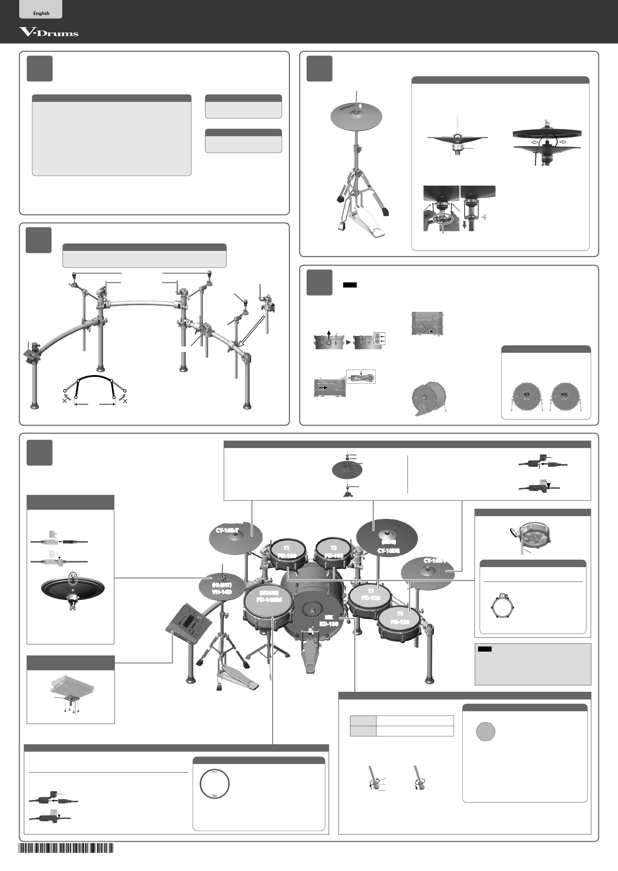
1.
Connect the L-shaped plug of the cables included with the
stand (MDS-STG2) to the drum sound module (TD-50X).
2.
Connect the L-shaped plugs of the cables to each pad.
The names on the labels correspond to trigger input jack
names as follows.
Marking label KIK T1 T2 T3 T4
TRIGGER IN jack KICK TOM 1 TOM 2 TOM 3 TOM 4
Marking label CR1 CR2 AX1 AX2 AX3 AX4
TRIGGER IN jack CRASH1 CRASH2 AUX 1 AUX 2 AUX 3 AUX 4
L-shaped Plug
Use the cable clips as shown above,
to secure the cables.
Cable clip
Cable
Connect PD-140DS (snare), CY-18DR (ride) and
VH-14D (hi-hat)
Insert the plug of the connection cable
into the TD-50X’s DIGITAL TRIGGER IN
port.
* You may connect to any of the
ports 1–3.
* To prevent malfunction and equipment failure, always turn down the volume, and turn o all the units before making any connections.
9 Settings for the snare (PD-140DS), ride cymbal (CY-18DR) and hi-hat (VH-14D)
1.
Press the [ENTER] button.
2.
Use the cursor buttons to select “PD140DS,” “CY18DR” or “VH14D.”
The rst time you connect the PD-140DS, CY-18DR and VH-14D to the DIGITAL TRIGGER IN port, the following screen will appear.
As directed in the screen, assign the PD-140DS as snare, assign CY-18DR as ride, and assign VH-14D as hi-hat.
* If you specify the same trigger input as a pad that is connected to a TRIGGER IN jack, the pad that’s connected to that TRIGGER IN jack won’t produce sound.
3.
Use the [–] [+] buttons or the dial to specify the Assign.
PD140DS SNARE
CY18DR RIDE
VH14D HI-HAT
4.
Press the [KIT] button to return to the DRUM KIT screen.
The setup described in this guide is for a right-handed drummer. If you want to use a left-handed setup,
leave the drum sound module (TD-50X) in the same position, but exchange the position of each pad and
cymbal (together with its mounting clamp) left for right.
If you do this, some of the cables will not be long enough, so use commercially available extension cables
(TRS 1/4” phone female , TRS 1/4” phone male) to adjust the cable length.
9 When you’ve nished making connections, turn on the power as described in “TD-50X Quick Start,” and
verify that you can hear sound.
This completes assembly and connections.
Have fun playing the drums!
9 Set the trigger bank to “TD-50KV2”
1.
Press the [TRIGGER] button.
2.
Press the PAGE [UP] button several times to access the top page.
3.
Press the [F1] (BANK) button.
The TRIGGER BANK screen appears.
Trigger bank number
Trigger type
4.
Place the cursor on the trigger bank number, and use the [-] [+] buttons or the
dial to set the trigger bank to “TD-50KV2.”
5.
Press the [KIT] button to return to the DRUM KIT screen.
NOTE
• Use the CY-16R-T as a crash cymbal. Bell
hits cannot be used.
• To connect TOM 4, use the trigger cable
included with the TD-50KV2.
9 Adjust the hi-hat (VH-14D)
When using the VH-14D, be sure to adjust the oset and hi-hat on the TD-50X after connecting.
This adjustment is required in order to correctly detect open, close, and pedal operations.
NOTE
* Continuous playing may cause dis-coloration of the pad, but this will
not aect the Pad’s function.
* See the VH-14D Owner’s Manual for details on the hi-hat.
Fixing the cables
Secure the cable in place
with the cable tie
Leave some slack in
the cable
Be sure to make this
small plastic hook
visible from
you.
Wind a cable tie around the
pipe and tighten it in order
not to slip.
Wind a cable tie around a
cable.
Insert the small plastic
hook to a hole to secure
the cable to the cymbal
arm.
USING THE UNIT SAFELY IMPORTANT NOTES
Plug
&
BOW/EDGE
OUTPUT jack
* BELL OUTPUT jack is
not used.
Connecting the pads and drum sound module
Time required: approx.
10
min.
1.
Press the TD-50X’s [TRIGGER] button.
2.
Press the PAGE [UP] button several times to access the
top page.
3.
Press the [F4] (HI-HAT) button.
The TRIGGER HI-HAT screen appears.
4.
Press the [F5] (OFFSET) button.
The VH OFFSET ADJUSTMENT screen appears.
5.
Loosen the clutch screw of the top cymbal and let it sit
on the bottom cymbal.
* Do NOT touch the hi-hats or the pedal.
Clutch screw
6.
Press the [F5] (EXECUTE) button.
The “VH oset” parameter is set automatically (approx. 3
seconds).
The [TRIGGER] button stops ashing and remains lit.
MEMO
You can also press the [TRIGGER] button while holding
down the [KIT] button on the TD-50X to adjust the oset.
When rst connecting the VH-14D to the drum sound
module, the trigger parameters are set to the recom-
mended values.
The trigger parameters may need to be adjusted
depending on the environment where the VH-14D is used,
including how it is mounted and the position in which it
is set up. Refer to the Owner’s Manual of the drum sound
module you are using for details on how to congure the
settings.
Adjusting the oset
Adjusting the hi-hat
1.
Adjust the gap between the top cymbal and bottom cymbal to
a clearance of approximately 10 mm, then tighten the clutch
screw.
Clutch screw
10 mm
* Although the gap can be adjusted to a clearance that makes
playing the hi-hat easier, setting too narrow or wide a gap
can cause improper function of the unit and prevent the
hi-hat from sounding as you intend. Setting the gap to 10 mm
provides the most natural feel when playing the VH-14D.
2.
Change the spring tension by adjusting the hi-hat stand.
For instructions on adjusting the tension, refer to the owner’s
manual for your hi-hat stand.
* If the spring tension is too high or too low, the hi-hat may not
operate correctly and you might not be able to play the way
you intended.
* The tension may not be adjustable on some stands.
Marking label