
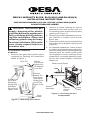
CAUTION: Turn off the gas
supply, disconnect the electric
circuit and allow the appliance to
fully cool down before perform-
ing this installation. Glass and
refractory panels may be heavy
for some individuals. If this is the
case, please request help from
someone else.
ACCESSING FIREBOX
All Models
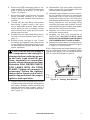
1. Remove both glass door panels (when
equipped) by following the instructions
shown in Figure 1.
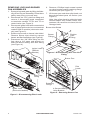
2. Remove 2 screws retaining the screen
assemblies and slide screen rods out
of mounting holes located behind facial
opening (see Figure 2).
3. Remove any hearth treatments (lava rock,
pan material or embers) from around
burner pan.
4. Remove front brick access panel by lifting
and angling out of replace opening (see
Figure 2).
5. On exposed installations, further access
to control compartment may be gained by
removing lower panel from facial opening.
Remove panel by carefully pulling with
your ngertips in louver openings (when
equipped) or, on smooth panels by push-
ing out from inside replace until panel
snaps free.
www.desatech.com
Figure 1 - Removing Glass Doors
Brick Access Panel
Figure 2 - Accessing Control
Compartment
Fold Bi-Fold
Door After
Releasing
Spring Clip
and Slide
Door Out of
Upper Track
Spring
Clip (Press
Spring Clip
To Release
Pivot Pin)
Remove
Bottom Pin
From Pivot
Plate While
Sliding Door
Out Of The
Upper Track
Pivot
Plate
Lower
Panel
Control
Access
Cover
Screen
Assembly
Pivot Pin
BRICK LINER KITS BL32S, BL36(H)(S) AND BL42(H)(S)
INSTALLATION INSTRUCTIONS
FOR USE WITH MODELS (V)P324, (V)P325, (V)M36 AND (V)M42
B-VENT FIREPLACE SERIES

www.desatech.com
110181-01C2
Figure 3 - Disconnecting Pilot Leads
Ignitor Lead
(Millivolt
Models)
Ignitor Lead
(Electronic Models)
Thermopile Lead
Pilot Tube
Fitting
REMOVING LOGS AND BURNER
PAN ASSEMBLIES
1. Remove logs and grate by lifting individu-
ally off burner pan assembly. Place them
safely away from your work area.
2. Disconnect the 7/16" pilot line tting and
remove 2 thermopile leads connected
to terminals marked TP/TH and TP on
control valve (see Figure 3).
3. Disconnect ignitor lead wire connected at
rear of piezo ignition device or at terminal
marked IGN on module (electronic mod-
els) (see Figure 3).
4. Remove top screw on burner inlet shield.
Remove burner inlet shield to expose
burner and ex line ttings (see Figure 4).
5. Disconnect the 3/8" are tting on ex
line using a 3/4" open end wrench on
both the burner tting and are tting
(see Figure 4).
Burner Inlet Shield
Flexline
Flare
Fitting
Figure 4 - Disconnecting Gas Flex Line
Fitting
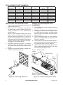
Figure 5 - Removing Burner Pan
Pilot
Leads
4 Screws Holding
Valve Bracket
Retaining
Flange
Burner
Fitting
Burner Pan
6. Remove 4 Phillips head screws located
on valve bracket and lift retaining ange
off burner pan (see Figure 5).
7. Lift burner pan and draw pilot leads out
through knockout pass on rebox (see
Figure 5).
Note: Use a free hand to guide the leads
around rebox from inside control com-
partment. Be careful not to bend, kink or
damage leads.

www.desatech.com
110181-01C 3
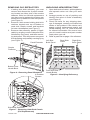
REMOVING OLD REFRACTORY
1. If adding side brick refractory, you must
remove and discard the 2 panel extend-
ers located on either side of the smoke
deector. If this is a full brick replacement
you also need to replace the bottom rear
hearth brick in addition to the side panels
(see Figure 6).
2. Remove 2 hex screws holding side brick
retainers located near top of rebox on
each side. Retain screws and brackets
for later reinstallation (see Figure 7).
3. Remove side refractory panels (if appli-
cable) by angling out one side panel rst,
followed by rear panel, and then remain-
ing side panel. This will prevent rear panel
from dropping and possibly causing injury
(see Figure 7).
Figure 6 - Removing Panel Extenders
Panel Extender
Bottom Rear
Hearth Brick
Figure 7 - Removing Side Brick Panels
(Full Replacement)
4 Retainer
Screws
Side Brick Retainers
Smoke
Deector
Figure 8 - Identifying Refractory
Left Side
Brick Panel
Rear Brick
Panel
Right Side
Brick Panel
Front and Rear
Hearth Bricks
UNPACKING NEW REFRACTORY
1. Open both ends of carton, split lengthwise
and spread carton out near your work
area.
2. Arrange panels on top of packing and
identify each piece in order of assembly
(see Figure 8).
3. Check all items for any shipping dam-
age. If damaged, contact your authorized
dealer of this product. If the dealer can’t
supply original replacement part(s) call
DESA Heating, LLC at 1-866-672-6040
for referral information. Be sure to have
your kit model number and part number
ready when you call.
6. Refer to parts list on page 4 for reference.

www.desatech.com
110181-01C4
REPLACEMENT PART NUMBERS
KIT MODEL
Left Side Brick
Panel
Right Side
Brick Panel
Rear Brick
Panel
Rear Hearth
Brick
Front Hearth
Brick
BL32S 108434-01 108432-01 108430-01 108426-01 108428-01
BL36S 106658-01 106659-01 106660-01 106661-01 106662-01
BL36 106658-02 106659-02 106660-02 106661-02 106662-02
BL36HS 108164-01 108165-01 108166-01 108167-01 108168-01
BL36H 108164-02 108165-02 108166-02 108167-02 108168-02
BL42S 107812-01 107814-01 107816-01 107818-01 107820-01
BL42 107812-02 107814-02 107816-02 107818-02 107820-02
BL42HS 108169-01 108170-01 108171-01 108172-01 108173-01
BL42H 108169-02 108170-02 108171-02 108172-02 108173-02
INSTALLING NEW REFRACTORY
1. Locate oval knockout pattern at bottom of
right side brick panel.
2. Place end of a 1" diameter wood dowel
or metal pipe inside knockout area and
punch out entire 1" x 1.5" slotted area
(see Figure 9).
NOTE: Clean bottom hearth pan of all
debris before installing bottom hearth
brick to prevent obstruction. To insure a
proper t of burner pan and valve bracket,
there must be 3/8" of clearance from back
edge of control access opening and lead-
ing edge of rear hearth brick.
3. Reinstall refractory panels in reverse
order starting with bottom rear hearth
brick, then rear panel and then both side
panels.
4. Replace 2 side brick retainers using 4 hex
screws removed previously.
Figure 9 - Removing Knockout
Figure 10 - Reconnecting Pilot Leads
Ignitor Lead
Red (TP)
White (TP/TH)
Piezo
Ignitor
Control Valve
Pilot
Fitting
REINSTALLING BURNER PAN
ASSEMBLY
1. Pull gas ex line back through knockout
hole in rebox.
2. Replace burner pan assembly, while
feeding pilot leads back through knock-
out. With your free hand, carefully guide
lines around outer rebox and into control
compartment.
3. Place retaining ange on valve bracket
back over leading edge of burner pan (see
Figure 5, page 2).
4. Center pan to valve bracket and replace 4
pan head screws into valve bracket mount-
ing locations (see Figure 5, page 2).
5. Hand thread pilot line tting into control
valve outlet and tighten using a 7/16" open
end wrench (see Figure 10).

www.desatech.com
110181-01C 5
Figure 11 - Adding Pan Material
6. Reconnect RED thermopile lead to ter-
minal marked TP and WHITE thermopile
lead to terminal marked TP/TH (see
Figure 10, page 4).
7. Reconnect ignitor lead at back of piezo
ignitor (millivolt models) or on control
module terminal marked IGN (electronic
models).
8. Thread 3/8" ex line tting onto burner
are tting. Tighten using a 3/4" open
end or adjustable wrench. Make certain
burner does not spin or misalign, burner
tubes should have main gas port holes
facing down into pan.
9. Reattach burner inlet shield with screw in
top hole of burner bracket (see Figure 4,
page 2).
10. Restore power and gas to unit. Follow
the safety and lighting instructions found
on the appliance information tag to check
for gas leaks and proper pilot and main
burner operation.
CAUTION: Be sure to inspect
the components and wiring for
damage before restoring power
to the unit. Leak check all gas
lines, especially at connection
points, using noncorrosive leak
detection uid. NEVER CHECK
FOR LEAKS WITH AN OPEN
FLAME. Tighten all connects if
necessary. Follow the lighting
instructions found on the infor-
mation tag and check for proper
ignition and operation.
11. Replace vermiculite material back in burn-
er pan and smooth to height and grade of
pan edges. Reapply ember material and
replace grate into pan notches. Leave a
minimum of 1/2" air gap under grate bars.
See Figure 11.
12. Reassemble logs onto grate, beginning
with rear base log. See pages 6 and 7 for
various model log placement.
13. Reinstall right replace screen assem-
bly by inserting end rod into uppermost
mounting hole in right screen pocket.
Screw mounting lug into left most pilot
hole behind and towards center of upper
facing. Repeat for left assembly using
mounting lug to the right of center. Screen
rods should overlap at middle and readily
conceal into side screen pockets.
14. Replace the control access cover and
front brick access panel.
15. Reapply any lava rock treatments to
hearth floor. DO NOT PLACE LAVA
ROCK IN THE BURNER PAN OR NEAR
THE BURNER INLET SHIELD AREA.
16. Replace the glass doors (if equipped) by
following the instructions shown in Figure
1, page 1, in reverse order.
If any components are found damaged, con-
tact an authorized dealer for original DESA
replacement part(s) or call DESA Heating,
LLC at 1-866-872-6040 for referral.

www.desatech.com
110181-01C6
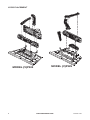
MODEL (V)P324
MODEL (V)P325
MODEL (V)M36
MODEL (V)M42
LOGS PLACEMENT

www.desatech.com
110181-01C 7
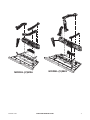
MODEL (V)P324
MODEL (V)P325
MODEL (V)M36
MODEL (V)M42

110181-01
Rev. C
11/08
NOT A UPC
110181 01
DESA Heating, LLC
2701 Industrial Drive
Bowling Green, KY 42101
www.desatech.com
1-866-672-6040
-
 1
1
-
 2
2
-
 3
3
-
 4
4
-
 5
5
-
 6
6
-
 7
7
-
 8
8


