Page is loading ...

X-SCALE TO X2 CONVERSION
FIELD UPGRADE PROCEDURES
(MODELS RL/FT5000/RT2000)
TDN 07100-00081-01 July 24, 2012
C
ORPORATE HEADQUARTERS:
21405 B Street
Long Beach, MS 39560
Phone: (800) 259-6672
Fax: (228) 868-9445
COPYRIGHT NOTICE
© 2012 Triton. All Rights Reserved. TRITON logo is a registered trademark of Triton Systems of Delaware.

2
X-SCALE TO X2 CONVERSION KITS
INTRODUCTION
This guide covers the steps for upgrading your current X-Scale terminal configuration (hardware/software) with X2 assemblies/
software. These procedures include a list of tools and hardware required for the conversion.
NOTE: Terminal Software is pre-loaded in the X2 main board assembly.
SCOPE
These procedures apply to all Triton certified service personnel involved in the process of maintaining or converting Triton ATMs.
STOP!
THIS INSTALLATION WILL REQUIRE REPLACEMENT OF THE X-SCALE MAIN BOARD. THE CURRENT
TERMINAL
PARAMETERS AND JOURNAL RECORDS WILL BE AFFECTED OR LOST. BEFORE PROCEEDING
WITH
THIS UPGRADE, IT IS HIGHLY RECOMMENDED THAT YOU FIRST - SAVE
TERMINAL PARAMETERS AND JOURNAL RECORDS TO AN EXTERNAL STORAGE
DEVICE
(USB THUMBDRIVE). THE PROCEDURES FOR SAVING AND RESTORING TERMINAL PARAMETERS
AND
SAVING JOURNAL RECORDS ARE LOCATED IN APPENDIX A.
N
OTE: JOURNAL RECORDS MAY ALSO BE SAVED USING TRITON CONNECT.
N
EXT, PRINT THE CONFIGURATION SUMMARY. YOU MAY ALSO WANT TO PRINT THE
JOURNAL
RECORDS AS WELL.
A
FTER RESTORING PARAMETERS, PRINT ANOTHER CONFIGURATION SUMMARY AND VERIFY THE SAVED
PARAMETERS
ARE CORRECT (YOU WILL HAVE TO RECONFIGURE THE CASSETTE SETUP/PARAMETERS).
ALSO VERIFY THE SCREEN/BUTTON OPTIONS AND PERFORM SOME DIAGNOSTICS ON THE HARDWARE
INSTALLED
. CHECK A PPENDIX A.
B
ELOW IS A CHECKLIST OF ITEMS THAT WE RECOMMEND YOU PERFORM OR CHECK PRIOR TO AND
AFTER
THIS UPGRADE:
TSILKCEHCNOITARUGIFNOC
noitpO noitcnuFtnemeganaM
yrammuSnoitarugifnoCsutatSlanimreT
)CT/lanimreT(noitacinummoCnoitarugifnoClanimreT
syeKgnikroWdaolnwoDtnemeganaMyeK
puteS/sretemaraPettessaCnoitarugifnoClanimreT
esolCettessaC/ettessaClairTsnoitcnuFesolClanimreT
esolCyaDsnoitcnuFesolClanimreT
egrahcruS/OSInoitarugifnoClanimreT
snoitpOneercS/scihparGnoitarugifnoClanimreT

3
FIELD UPGRADE PROCEDURE
CONTENTS
CONFIGURE DOCKING BOARD ASSEMBLY ...................................................................................................... 4
DOCKING BOARD BLOCK DIAGRAM ............................................................................................................. 5
INSTALLING THE RL5000 X2 UPGRADE KIT
OVERVIEW ............................................................................................................................................................................... 6
RL5000 PARTS KIT .................................................................................................................................................................. 7
REMOVE PAPER ROLL/SPINDLE ............................................................................................................................................... 8
REMOVE PCMCIA MODEM / PHONE LINE A DAPTER ............................................................................................................... 8
REMOVE X-SCALE MAIN BOARD ASSEMBLY ............................................................................................................................ 8
REMOVE DOCKING BOARD ASSEMBLY ...................................................................................................................................... 9
REMOVE / REPLACE PRINTER “PRESENTER” BOARD ................................................................................................................. 9
REMOVE / REPLACE PRINTER “CONTROLLER” ........................................................................................................................ 10
INSTALL NEW DOCKING BOARD ASSEMBLY ........................................................................................................................... 11
INSTALL / CONNECT NEW PRINTER CONTROLLER CABLES ...................................................................................................... 12
INSTALL NEW CARD READER CABLE ..................................................................................................................................... 12
INSTALL X2 MAIN BOARD ..................................................................................................................................................... 13
REMOVE REPLACED CABLES .................................................................................................................................................. 13
OPTIONAL MODEM / HARDWARE INSTALLATION ..................................................................................................................... 13
OPTIONAL POWER SUPPLY / TDM FIRMWARE UPGRADE OPTION .......................................................................................... 14
INSTALLING THE FT5000 X2 UPGRADE KIT
OVERVIEW ............................................................................................................................................................................. 15
FT5000 PARTS KIT ................................................................................................................................................................ 16
REMOVE PAPER ROLL/SPINDLE ............................................................................................................................................. 17
REMOVE PCMCIA MODEM / PHONE LINE A DAPTER ............................................................................................................. 17
REMOVE X-SCALE MAIN BOARD ASSEMBLY .......................................................................................................................... 17
REMOVE DOCKING BOARD ASSEMBLY .................................................................................................................................... 17
REMOVE / REPLACE PRINTER “PRESENTER” BOARD ............................................................................................................... 18
REMOVE / REPLACE PRINTER “CONTROLLER” ........................................................................................................................ 19
INSTALL NEW DOCKING BOARD ASSEMBLY ........................................................................................................................... 21
INSTALL / CONNECT NEW PRINTER CONTROLLER CABLES ...................................................................................................... 22
INSTALL NEW CARD READER CABLE ..................................................................................................................................... 22
INSTALL X2 MAIN BOARD ..................................................................................................................................................... 23
REMOVE REPLACED CABLES .................................................................................................................................................. 23
OPTIONAL MODEM / HARDWARE INSTALLATION ..................................................................................................................... 23
INSTALLING THE RT2000 X2 UPGRADE KIT 10.4 inch display ONLY
OVERVIEW ............................................................................................................................................................................. 24
RT2000 PARTS KIT ................................................................................................................................................................ 25
REMOVE PAPER ROLL/SPINDLE ............................................................................................................................................. 26
REMOVE PCMCIA MODEM / PHONE LINE A DAPTER ............................................................................................................. 26
REMOVE X-SCALE MAIN BOARD ASSEMBLY .......................................................................................................................... 26
REMOVE DOCKING BOARD ASSEMBLY .................................................................................................................................... 27
REMOVE / REPLACE PRINTER “PRESENTER” BOARD ............................................................................................................... 27
REMOVE / REPLACE PRINTER “CONTROLLER” ........................................................................................................................ 28
INSTALL NEW DOCKING BOARD ASSEMBLY ........................................................................................................................... 29
INSTALL / CONNECT NEW PRINTER CONTROLLER CABLES ...................................................................................................... 30
INSTALL NEW CARD READER CABLE ..................................................................................................................................... 30
INSTALL X2 MAIN BOARD ..................................................................................................................................................... 30
REMOVE REPLACED CABLES .................................................................................................................................................. 30
OPTIONAL MODEM / HARDWARE INSTALLATION ..................................................................................................................... 31
OPTIONAL POWER SUPPLY / TDM FIRMWARE UPGRADE OPTION .......................................................................................... 31
MOTORIZED CARD READER / TRITON MODEM PHONE CABLING .................................................................. 32
APPENDIX A .............................................................................................................................................. A-1

4
X-SCALE TO X2 CONVERSION KITS
CONFIGURE THE DOCKING BOARD
Before installing the upgrade kits, you must configure the docking board assembly dip switches for the model
units display. The following table shows the settings for configuring J1 (Video select).
Note: The RT2000 conversion kit is only available for the 10.4" display.
O N
1 2 3 4 5
J1
“DTR” required for Rear
Service Panel.
12V DTR
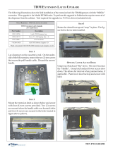
CONFIGURE THE REAR SERVICE PANEL JUMPER
If you have the Rear Service Panel (RSP) for the FT5000 or RT2000, you must also set the jumper for
your RSP (J11 located on the Docking Board assembly). The current FT5000 RSP (Figure 1) must have
the jumper set to “DTR”. The RT2000 RSP is a touchscreeen display (Figure 2) that must have the
jumper set to “12V”.
NOTE: The RSP shown in Figure 1 (for FT5000) will be replaced with the touchscreen display (Fig-
ure 2) at a date TBD. If your FT5000 comes with this touchscreen display, remember to set the jumper
to “12V”.
Figure 2. Touchscreen Operator Service Panel
Figure 1. Rear Service Panel (RSP).
J11
“12V” required for Operator
Service Panel (touchscreen)
SGNITTESNOITCELESDCL
tcudorP 1PID 2PID 3PID 4PID 5PID
K5TFNOFFONONOFFO
K5LRNOFFONONONO
K2TR
)"4.01(
NOFFONONOFFO
."NO"ottesyrotcafsgnitteshctiwsllA*
IDENTIFYING AN X2 CONVERTED UNIT
X-Scale to X2 field conversion requires numerous hardware items to be replaced. To identify a unit that has been field
upgraded with this kit, a label (shown below) may have been affixed to the X2 Main Board assembly for identification.
Attach the CE sticker to the white ID label.
Attach the CE sticker
to the white ID label.

5
Field Upgrade procedUre
J3 - Modem USB portJ2 - Printer USB port
J5 - Mono LCD
(RT mono display)
J4 - Color LCD
J7 - Inverter power
J8 - Fan power
J9 - Debug
(not used)
J10 - SPED/VEPP
(RJ-45 port)
J12 - Auxillary
(RJ-45 port)
J11 - Rear Service Panel
(jumper - 12V / DTR)
J14 - Card reader
J16 - UPS
(RJ-45 port)
J15 - RL / FT
Headphones
J17 - RT Headphones
J18 - RL / FT LEDs
J23 - Docking Board power
J19 - RT LEDs
J20, J21 - Switch
(Door alarms
- not used)
DISPENSER
J13 - Dispenser
(RJ-45 port)
AUXILLARYS.P.E.D.
docking Board
J1 -Video select
(Dip switches)

6
X-SCALE TO X2 CONVERSION KITS
RL5000 X-SCALE TO X2 UPGRADE CONVERSION
OVERVIEW
The X-Scale to X2 conversion requires replacement of numerous hardware items.
The following items (minimum) will be replaced from the current
RL5000 X-Scale hardware configuration:
If you ordered the optional Modem kit and/or Power Supply-
TDM Upgrade kit(s), the following items will also be replaced:
X-SCALE A SSEMBLIES
(THAT WILL BE REPLACED)
""
""
" MAIN BOARD ASSEMBLY
""
""
" DOCKING BOARD
""
""
" PRINTER ASSEMBLIES
PRINTER CONTROLLER
POWER CABLE (PRINTER CONTROLLER)
LOW PAPER SENSOR CABLE
DATA CABLE (RIBBON)
PRESENTER BOARD
PRESENTER CABLE
CONTROLLER COVER
""
""
" CARD READER CABLES
(DIP, EMV, MOTORIZED) - APPLICABLE
NOTE: If your RL5000 is equipped with a
TDM dispensing mechanism (any), you will
be required to replace the “single” power sup-
ply currently install and upgrade the TDMs
firmware software. You will require a PC or
laptop computer to perform the TDM upgrade
procedure.
""
""
" PCM/CIA MODEM AND PHONE LINE
ADAPTER
""
""
" POWER SUPPLY
PCMCIA MODEM
AND
ADAPTER
MAIN BOARD
DOCKING
BOARD
“PRESENTER”
BOARD
PRINTER CONTROLLER
AND
CABLES

7
FIELD UPGRADE PROCEDURE
REQUIRED PARTS AND TOOLS
DERIUQERSLOOT
)dednemmocercitengaM(revirdwercsspillihP2#dna1#
revirdtun)mm9("23/11-srettuclanogaiD
drocgnidnuorghtiwpartstsirwDSE
0005LRS-X
CALE TO
2XU
PGRADE
K
IT
82202-00260
DEDECREPUSEBYAMSREBMUNTRAPEMOS-DEILPPUSSTRAP
SREBMUNTRAP NOITPIRCSED YTITNAUQ
20300-00070lebaLtiKedargpU2X
1
77000-01190ylbmessAdraoBniaM2X1
00400-00190)yalpsidroloC(draoBgnikcoD1
91101-00510elbaCdnarettuC/BSU,retnirP,draoBrellortnoC1
46070-02190
retnirP,elbaCrewoP
"13
1
06070-02190
BSU,retnirP,elbaCataD
"24
1
04300-02190rosneSrepaPwoL,elbaC1
85200-00190
BCP
,
draoBretneserP
1
93300-02190retneserPretnirP,elbaC1
43810-11030rellortnoCretnirP,revoC1
tiKmedoM
41200-51030 notirT,BSU,medoM 1
96070-02190 BSU,medoM,elbaC 1
01810-11030 edoM,tekcarBgnitnuoMm 1
27100-45020 daeh-rehsaW,spillihP,wercS 5
tiKedargpUMDTdnaylppuSrewoP)32180-00260N/P(
90100-00290 )lauD(ylppuSrewoP 1
23070-02190 MDT,retpadAylppuSrewoP,elbaC 1
41070-02190 elbaCdaolnwoDMDT 1
selbaCredaeRdraC
*
35070-02190
)VME(56I,redaeRdraC,elbaC 1
*
72800-02190
)piD(512ketgaM,redaeRdraC,elbaC
1
*
48200-02190
)dezirotoM(5K3,redaeRdraC,elbaC 1
51000-27030parWyT51
epytredaerdracelbacilpparofelbacesU*

8
X-SCALE TO X2 CONVERSION KITS
Paper feeds
over bar
Note: Before proceeding with the upgrade procedures, terminal power MUST be removed. Enter MANAGEMENT FUNCTIONS > SYSTEM
PARAMETERS > SHUT DOWN THE TERMINAL. When prompted “It is now safe to turn off your computer”on the screen, open the control
panel and turn the power switch on the power supply to the <OFF> (0) position.
INSTALLING THE RL5000 X2 UPGRADE KIT
1. REMOVE PAPER ROLL - Open the control panel and remove the paper roll/spindle from the receipt printer.
Open control panel. Remove paper roll from printer
3. REMOVE MAIN BOARD ASSEMBLY - Pull the release pin on the main board assembly and slide assembly from docking board. This
assembly will be replaced.
Pull release pin and slide assembly. Main board removed.
2. REMOVE PCMCIA MODEM AND PHONE LINE A DAPTER (IF APPLICABLE) - Disconnect the phone line from the phone line adapter.
Push the release button for the modem card slot and remove both the PCMCIA modem card and phone line adapter.
Release
Push release button.
Remove PCMCIA modem card and phone line adapter.

9
FIELD UPGRADE PROCEDURE
5. REMOVE/REPLACE PRINTER “PRESENTER” BOARD:
4. REMOVE DOCKING BOARD ASSEMBLY - Disconnect all cables to the docking board. Using a phillips screwdriver, remove the screw
that secures board and remove the docking board. This assembly will be replaced. Retain the screw.
Remove all cables from docking board.
Docking board removed.
A. Disconnect the printer presenter board cable. This cable will be replaced.
B. Using a phillips screwdriver, remove the two (2) screws that secure the presenter board. Retain the screws. Next, disconnect
the two (2) wire cable from the board and remove the board. This board will be replaced.
Presenter board cable.
C. Connect the two (2) wire cable previously removed to the new presenter board and secure board to the presenter with the
screws previously removed.
Remove screws.
New presenter board installed.

10
X-SCALE TO X2 CONVERSION KITS
6. REMOVE/REPLACE PRINTER “CONTROLLER” ASSEMBLY:
C. Disconnect the remaining cables to the printer controller board. Next, using a phillips screwdriver, remove the four (4)
screws that secure the board to the printer bracket. Remove the controller board - this will be replaced. Retain these screws.
All cables removed from
old controller board.
A. Remove the printer controller board cover, if installed. Disconnect the power, data, and low paper sensor cables from the
printer controller board and from the low paper sensor board shown. These cables and the cover will be replaced.
Printer controller cover.
Printer controller cables.
Low paper
sensor cable
Data cable
Power cable
B. Disconnect the card reader cable from the card reader. Using a phillips screwdriver, remove the screw that secures the TVS
pack from the printer bracket shown below. Remove the card reader/TVS pack cable. This will be replaced in later steps.
Disconnect/remove card
reader cable .
TVS pack

11
FIELD UPGRADE PROCEDURE
D. Install the new printer controller (P/N 01260-00022/23) with screws previously removed. Ensure screws are securely
tightened! Note: The USB port on the assembly will be facing UP when installed. Reconnect the cables removed in Step 6(C).
New controller with lower cables installed.
USB port
7. INSTALL NEW DOCKING BOARD A SSEMBLY - Note: Before installing, verify the video select dip switches have been properly set
for the RL5000. See page 4 for correct settings.
Using the screw previously removed from old docking board, install new assembly and secure.
Reconnect: DISPLAY LCD RIBBON CABLE (J4) RL/FT HEADPHONE CABLE (J15)
INVERTER CABLE (J7) RL/FT LED CABLE (J18)
SPED RJ-45 CABLE (J10) DOCKING BOARD POWER CABLE (J23)
DISPENSER RJ-45 CABLE (J13) USB MODEM (MULTITECH TYPE, IF APPLICABLE) - (J3)
Docking board installed and some cables connected.
Note: Refer to the Docking Board diagram on Page 5 for connector designations.
* IMPORTANT *
The RL5000 display cable (ribbon) may have a ferrite attached
to it. REMOVE THE FERRITE (open it up) before connecting the
cable to the docking board. The ferrite is no longer required
for the X2 upgrade.
Note: The rest of the printer controller cables will be installed in Step 8.

12
X-SCALE TO X2 CONVERSION KITS
9. REMOVE / REPLACE CARD READER CABLE - Connect the new card reader cable to the reader. Connect the other end to the DOCKING
BOARD (J14).
Note: Upgrade kits come with multiple cable types. Install the applicable cable to your card reader type (EMV, Dip,
Motorized).
Install new card reader cable.
A. Connect the new power (P/N 09120-07064), low paper sensor (P/N 09120-00340), and USB data (P/N 09120-07060) cables to
the printer controller. Next, install one end of the new printer presenter board cable (P/N 09120-00339) to the presenter board and
other end to the printer controller. Note that the presenter cable no longer is connected to the docking board.
B. Route the power cable and connect to the power supply. Route the USB data cable to the DOCKING BOARD and connect to
the PRINTER USB PORT ( J2).
Connect new cables to controller assembly.
C. Install the new printer controller cover (P/N 03011-01834).
Route cables under strut.
Presenter board.
8. INSTALL /CONNECT NEW PRINTER CONTROLLER CABLES:
USB data
Presenter
Low paper
sensor
Power

13
FIELD UPGRADE PROCEDURE
11. REMOVE ALL REPLACED CABLES - All cables that have been replaced may be removed from the unit. Route the new cables and
secure together with the Ty wraps included, if preferred.
All cables routed/connected to Docking board.
10. INSTALL NEW X2 MAIN BOARD ASSEMBLY - Align tabs on X2 main board with slots on display assembly. Slide main board into
docking board assembly until the green handle locks in place.
X2 main board installed.
OPTIONAL MODEM ASSEMBLY / HARDWARE - The following shows installation of the optional Triton USB modem and the bracket/
cable included.
! Using a phillips screwdriver, remove the two (2) screws shown from each panel cap located on the control panel (Figures 1 and
2). Retain the screws.
Note: If your ATM has the panels removed due to topper signage, use the screws (Qty. 5) included in kit for the next step.
Remove 2 screws.
Panel cap
Panels caps removed for hightopper signage.
X2 Main Board
USB PORTS
RJ-45 (CAT-5)
TCP/IP PORT

14
X-SCALE TO X2 CONVERSION KITS
Mount/connect new modem.
Modem slots.
Using the four (4) screws previously removed, install the new modem bracket. Next, install the new Triton USB modem by
aligning the slots on the bottom of the modem with the tabs on the bracket. Slide modem assembly until it snaps in place.
Connect the modem USB cable (P/N 09120-07069) to the modem and Docking board USB
PORT (J3). Last, reconnect the
phone line cable to the modem.
Install new modem bracket.
OPTIONAL POWER SUPPLY AND TDM UPGRADE KIT OPTION:
The Power Supply replacement procedures are available on the Triton web site.. The document (TDN 07103-00163) describes the
steps involved.
The TDM Firmware Upgrade procedure (TDN 07103-00168) and software are also available on the Triton web site. The
download cable (P/N 09120-07014) and TDM adapter cable (P/N 09120-07032) are included with this optional kit accessories.
You will need a PC or laptop computer to perform the firmware update.

15
FIELD UPGRADE PROCEDURE
FT5000 X-SCALE TO X2 UPGRADE CONVERSION
OVERVIEW
The X-Scale to X2 conversion requires replacement of numerous hardware items.
The following items (minimum) will be replaced from the current
FT5000 X-Scale hardware configuration:
If you ordered the optional Modem kit, the following items will
also be replaced:
!!
!!
! MAIN BOARD ASSEMBLY
!!
!!
! DOCKING BOARD
!!
!!
! P
RINTER A SSEMBLIES
PRINTER CONTROLLER
POWER CABLE (PRINTER CONTROLLER)
LOW PAPER SENSOR CABLE
DATA CABLE (RIBBON)
PRESENTER BOARD
PRESENTER CABLE
CONTROLLER COVER
!!
!!
! CARD READER CABLES
(DIP, EMV, MOTORIZED) - APPLICABLE
!!
!!
! PCM/CIA MODEM AND PHONE LINE
ADAPTER
PCMCIA MODEM
AND
ADAPTER
MAIN BOARD
DOCKING
BOARD
PRINTER CONTROLLER
AND
CABLES
X-SCALE A SSEMBLIES
(THAT WILL BE REPLACED)
“PRESENTER”
BOARD
(LOCATED ON
PRESENTER
)

16
X-SCALE TO X2 CONVERSION KITS
REQUIRED PARTS AND TOOLS
DERIUQERSLOOT
)dednemmocercitengaM(trohsdnagnol-revirdwercsspillihP2#dna1#
revirdxroT02-T#srettuclanogaiD
drocgnidnuorghtiwpartstsirwDSE
0005TFS-X
CALE TO
2XU
PGRADE
K
IT
92202-00260
DEDECREPUSEBYAMSREBMUNTRAPEMOS-DEILPPUSSTRAP
SREBMUNTRAP NOITPIRCSED YTITNAUQ
20300-00070lebaLtikedargpU2X1
77000-01190ylbmessAdraoBniaM2X1
00400-00190)yalpsidroloC(draoBgnikcoD1
91101-00510
BSU,retnirP,draoBrellortnoC
elbacdnarettuC/
1
56070-02190
retnirP,elbaCrewoP
"05
1
95070-02190
BSU,retnirP,elbaCataD
"02
1
86070-02190
rosneSrepaPwoL,elbaC
"41
1
85200-00190
BCP
,
draoBretneserP
1
26070-02190
etneserPretnirP,elbaC
"32
1
53810-11030rellortnoCretnirP,revoC1
02000-45020rehsawenoC,"4/1,04-4#,wercS5
06100-45020daeh-spillihP,naPgnippaT"4/1,04-4#,wercS2
medoM
41200-51030 notirT,BSU,medoM 1
96070-02190
BSU,medoM,elbaC
"5.5
1
63810-11030 ,medoM,tekcarBgnitnuoM)TR/TF( 1
selbaCredaeRdraC
*
35070-02190
)VME(561,redaeRdraC,elbaC 1
*
72800-02190
)piD(512ketgaM,redaeRdraC,elbaC 1
*
48200-02190
)dezirotoM(5K3,redaeRdraC,elbaC 1
51000-27030parWyT51
epytredaerdracelbacilpparofelbacesU*

17
FIELD UPGRADE PROCEDURE
Note: Before proceeding with the upgrade procedures, terminal power MUST be removed.
INSTALLING THE FT5000 X2 UPGRADE KIT
1. REMOVE PAPER ROLL - Open rear cabinet door. Remove the paper roll/spindle
from the receipt printer.
FROM FRONT DISPLAY: Enter MANAGEMENT FUNCTIONS > SYSTEM PARAMETERS > SHUT DOWN THE TERMINAL. When prompted “It is
now safe to turn off your computer”on the screen, open the cabinet sleeve door and turn the power switch on the power supply to
the <OFF> (0) position.
FROM REAR SERVICE OPERATOR PANEL (FT/RT): Enter MANAGEMENT FUNCTIONS > MAIN MENU > SHUT DOWN THE TERMINAL. When
prompted “It is now safe to turn off your computer”on the screen, open the cabinet sleeve door and turn the power switch on the
power supply to the <OFF> (0) position.
3. REMOVE MAIN BOARD ASSEMBLY - Pull the release pin on the main board
assembly and slide unit from docking board. This assembly will be replaced.
Paper roll removed.
Pull release pin and slide assembly.
Main board removed.
4. REMOVE DOCKING BOARD A SSEMBLY - Disconnect all cables to the docking board. Using a phillips screwdriver, remove the screw
that secures board and remove the docking board. This assembly will be replaced. Retain the screw.
Remove all cables/
screw from docking
board.
Docking board removed.
2. REMOVE PCMCIA MODEM AND PHONE LINE ADAPTER (IF APPLICABLE) -
Disconnect the phone line from the phone line adapter. Push the release
button for the modem card slot and remove both the PCMCIA modem card
and phone line adapter.

18
X-SCALE TO X2 CONVERSION KITS
5. REMOVE/REPLACE PRINTER “PRESENTER” BOARD:
A. Lift the printer handle and rotate the printer assembly down.
C. Remove the two (2) Torx screws with a #20 Torx driver. Next, remove the two (2) phillips head screws. Retain all the screws.
D. Disconnect the presenter cable and remove the presenter. The presenter board cable will be replaced.
B. The presenter is secured to the printer bracket (2 Torx screws) and control panel (2 phillips head screws).
E. Place the presenter assembly on a flat surface. Using a phillips screwdriver, remove the two (2) screws that secure the
presenter board shown. Next, disconnect the two (2) wire cable from the board and remove the board. This will be replaced.
Pull handle and rotate printer assembly down.
Presenter screw locations.
Remove Torx screws.
Remove phillips screws.
Disconnect presenter cable.
F. Connect the two (2) wire cable previously removed to the new presenter board and secure board to the presenter with the
screws previously removed.
Phillip screws
Torx screws
Presenter board
Presenter circuit
board.
Presenter board
removed.

19
FIELD UPGRADE PROCEDURE
J. Rotate the printer assembly up until it locks in place.
6. REMOVE/REPLACE PRINTER “CONTROLLER” ASSEMBLY:
A. Remove the printer controller cover. This cover will be replaced. Disconnect all the cables to the printer controller board.
Also, disconnect the low paper sensor cable end from the sensor board.
Note: The printer controller power, data, and low paper sensor cables will be replaced.
B. Using a phillips screwdriver, remove the four (4) screws that secure the board to the printer assembly and remove the
controller board - this will be replaced. Note: The screws will also be replaced.
Printer controller cables.
All cables removed from old
controller board. Printer controller removed.
H. Connect the new presenter board cable (P/N 09120-07062) to the presenter board. The other end will be connected later to
the new printer controller assembly.
Start phillips head screw.
I. Insert the presenter assembly on the screw and start the other.
DO NOT tighten the phillips head screws at this time. Next, install
the Torx screws previously removed. Tighten all screws.
G. Using a phillips screwdriver, start one (1) of the phillips head screws previously removed in the control panel.
Grasp handle and rotate printer
assembly up.
** IMPORTANT **
After installation of presenter assembly, check to ensure the flapper
door moves freely. The LED wires and speaker wires should be
clear of the flapper door. Also, the jam clearance door
MUST be
closed to process receipts.
Clearance door
Flapper
door

20
X-SCALE TO X2 CONVERSION KITS
C. Place the new printer controller cover on a flat surface. Install the new printer controller (P/N 01260-00022/23) inside the
cover and secure with four (4) conehead phillips head screws included in kit.
Ensure the screws are securely tightened! Note:
The USB port on the assembly will be facing towards the “cutout” on the cover.
New printer controller cover.
Printer controller installed in cover.
D. Connect cables to printer controller board:
Reconnect the printer cables to the new controller board. Note: If these cables are ty wrapped and hard to connect,
recommend carefully cut ty wrap to better access cables for connectivity to the controller.
Connect the new power (P/N 09120-07065) and low paper sensor (P/N 09120-07068) cables to the printer controller.
Connect the new presenter board cable (P/N 09120-07062) previously installed to the presenter in Step 5(H) to the
controller board. Note that this presenter cable no longer is connected to the docking board.
Location of cable connections.
USB “cutout”
access
Power
Presenter
Low paper
sensor
/