Page is loading ...

TABLE OF CONTENTS
Introduction. . . . . . . . . . . . . . . . . . . . . . . . . . . . . . . . . . . . . . . . . . . . . . . . . 2
Features. . . . . . . . . . . . . . . . . . . . . . . . . . . . . . . . . . . . . . . . . . . . . . . . . . . . 3
Safety Precautions. . . . . . . . . . . . . . . . . . . . . . . . . . . . . . . . . . . . . . . . . . . 4
Unpacking. . . . . . . . . . . . . . . . . . . . . . . . . . . . . . . . . . . . . . . . . . . . . . . . . . 6
CN4321
Model Configuration . . . . . . . . . . . . . . . . . . . . . . . . . . . . . . . . . . . . . . . 7
Specifications. . . . . . . . . . . . . . . . . . . . . . . . . . . . . . . . . . . . . . . . . . . . . 8
Outer Dimensions and Panel Cutout Size . . . . . . . . . . . . . . . . . . . . . 13
Installation . . . . . . . . . . . . . . . . . . . . . . . . . . . . . . . . . . . . . . . . . . . . . . 14
Wiring Instructions: . . . . . . . . . . . . . . . . . . . . . . . . . . . . . . . . . . . . . . 15
Front Panel Description. . . . . . . . . . . . . . . . . . . . . . . . . . . . . . . . . . . . 16
Front Panel Operation . . . . . . . . . . . . . . . . . . . . . . . . . . . . . . . . . . . . . 17
CN4431
Model Configuration . . . . . . . . . . . . . . . . . . . . . . . . . . . . . . . . . . . . . . 19
Specifications. . . . . . . . . . . . . . . . . . . . . . . . . . . . . . . . . . . . . . . . . . . . 20
Outer Dimensions and Panel Cutout Size . . . . . . . . . . . . . . . . . . . . . 25
Installation . . . . . . . . . . . . . . . . . . . . . . . . . . . . . . . . . . . . . . . . . . . . . . 26
Wiring Instructions: . . . . . . . . . . . . . . . . . . . . . . . . . . . . . . . . . . . . . . 27
System Wiring Diagrams. . . . . . . . . . . . . . . . . . . . . . . . . . . . . . . . . . . 32
Front Panel Description. . . . . . . . . . . . . . . . . . . . . . . . . . . . . . . . . . . . 33
Front Panel Operation . . . . . . . . . . . . . . . . . . . . . . . . . . . . . . . . . . . . . 34
Autotuning. . . . . . . . . . . . . . . . . . . . . . . . . . . . . . . . . . . . . . . . . . . . . . . . . 36
Programming
Setup Menu . . . . . . . . . . . . . . . . . . . . . . . . . . . . . . . . . . . . . . . . . . . . . . 37
System Menu. . . . . . . . . . . . . . . . . . . . . . . . . . . . . . . . . . . . . . . . . . . . . 40
Factory Preset Menu . . . . . . . . . . . . . . . . . . . . . . . . . . . . . . . . . . . . . . 57
Error Messages . . . . . . . . . . . . . . . . . . . . . . . . . . . . . . . . . . . . . . . . . . . . 62
Appendix A: Autotuning. . . . . . . . . . . . . . . . . . . . . . . . . . . . . . . . . . . . . . 63
Appendix B: Manual Tuning . . . . . . . . . . . . . . . . . . . . . . . . . . . . . . . . . . 66
Appendix C: Heat/Cool Option. . . . . . . . . . . . . . . . . . . . . . . . . . . . . . . . . 75
Quick Reference. . . . . . . . . . . . . . . . . . . . . . . . . . . . . . . . . . . . . . . . . . . . 79

2
INTRODUCTION
The OMEGA
®
CN4321 and CN4431 controllers are economical
process controllers that accept temperature or process inputs, and
have sophisticated control capabilities, providing on/off control, PID, or
autotune PID, with Fuzzy Logic. They feature an 8-segment ramp/soak
function.
The CN4431 is a 1/16 DIN controller that has dual digital display for
simultaneous indication of process value and setpoint. It is available
with a single output that includes mechanical relay, 24V DC SSR driver,
or 4-20 mA output. Options available include alarms (configurable as
high/low, deviation, or zone alarm).
The CN4321 is a 1/32 DIN controller that has a single digital display.
It is available with either single or dual outputs; dual output models can
be used for heat/cool, heat/heat or cool/cool control. Output options
include mechanical relay and 5V DC SSR driver. It also has an optional
programmable alarm output.
The first section of this manual details the specifications and gen-
eral description for the CN4321 controller. The second section will cover
the CN4431 controller, followed by a detailed description of the pro-
gramming parameters, which are common to both the controllers. Sev-
eral appendices describe some of the controlling techniques. Finally, a
Quick Reference guide gives a listing of all the parameters and their
default values.

3
FEATURES
• Fuzzy Logic Control
• PID Autotune with manual over-
ride - heating or cooling
• Programmable control action -
reverse or direct
• Programmable cycle time
• Programmable inputs - Thermo-
couple/RTD, or Current/ Voltage
• Sensor burn-out protection
• Zero/span calibration
• Outputs: Relay, Solid-state relay
drive, or 4-20mA DC (4-20mA
not available on CN4321)
• Secondary output for
cooling (optional)
• High/low alarm
outputs (optional)
• Menu-driven format
• Setting – touch keys on front
panel
• Programmable 8-segment
ramp/soak function
• Digital filtering (to suppress
factory noise)
• Adjustable setpoint range
• Selectable °F/°C
• Offset adjustments
• Programmable decimal point
• Programmable lock-up feature
• Advanced security options to
prevent unauthorized parame-
ter changes
• 4-digit, LED indication
• Output status indication
• Fault indication
• Non-volatile memory
• 1/32 or 1/16 DIN panel mount
package with plastic bracket
• NEMA 4X faceplate
• ABS plastic housing
• Termination– terminal block
(CN4321) or socket with screw-
down terminals (CN4431)
• 85 to 264V AC free voltage
power supply
• 24V AC/DC optional power
supply (on CN4431 only)
• UL and C-UL recognized
• CE approved

4
SAFETY PRECAUTIONS
Before using this product, the user is requested to read the following
precautions carefully to ensure safety. The safety requirements are
classified as either “warning” or “caution” according to the following
explanations:
Warning
Wiring
1. If there is danger of serious accident resulting from a failure or
defect in this unit, provide the unit with an appropriate external pro-
tective circuit to prevent an accident.
2. The unit is normally supplied without a power switch or a fuse. Use
power switch and fuse as required (Rating of the fuse: 250V, 1A)
Power supply
1. Be sure to use the rated power supply voltage to protect the unit
against damage and to prevent failure.
2. Keep the power off until all of the wiring is completed so that electric
shock and trouble with the unit can be prevented.
General
1. Never attempt to disassemble, modify, or repair this unit. Tampering
with the unit may result in malfunction, electric shock, or fire.
2. Do not use the unit in combustible or explosive gaseous atmos-
pheres.

5
Caution
Installation
1. Avoid installing the unit in places where:
• the ambient temperature may reach beyond the range of -10 to 50°C
(14 to 122°F) while in operation
• the ambient humidity may reach higher than 90% RH while in
operation
• a change in the ambient temperature is so rapid as to cause
condensation
• corrosive gases (sulfide and ammonia gas, in particular) or
combustible gases are emitted
• the unit is subject to vibration or shock
• the unit is likely to come in contact with water, oil, chemicals, steam,
or vapor
• the unit is exposed to dust, salt, or air containing iron particles
• the unit is subject to interference with static electricity, magnetism,
or noise
• the unit is exposed to direct sunlight
• heat may be accumulated due to the radiation of heat
Maintenance
1. Do not use organic solvents such as alcohol or benzene to wipe this
unit. Use a neutral detergent.

UNPACKING
Remove the Packing List and verify that you have received all equipment,
including the following (quantities in parenthesis):
• Process controller (1)
• Mounting bracket (1)
• Socket with CN4431 (1)
• Operator’s manual (1)
• Waterproof gasket (1)
• 250Ω precision resistor (when required) (1)
• Current transformer (when required) (1)
If you have any questions about the shipment, please call the OMEGA
®
Cus-
tomer Service Department.
When you receive the shipment, inspect the container and equipment for signs
of damage. Note any evidence of rough handling in transit. Immediately report
any damage to the shipping agent.
Note:
The carrier will not honor damage claims unless all shipping materials are
saved for inspection. After examining and removing contents, save packing
material and carton in the event reshipment is necessary.
6

7
CN4321 MODEL CONFIGURATION
MODEL DESCRIPTION
Single Output Models
_________________________________________________________________
CN4321(*)-R1 1/32 DIN controller, relay output
CN4321(*)-D1 1/32 DIN controller, DC SSR driver output
_________________________________________________________________
Dual Output Models
_________________________________________________________________
CN4322(*)-R1-R2 1/32 DIN controller, dual relay output
CN4322(*)-D1-R2 1/32 DIN controller, DC SSR driver and relay output
_________________________________________________________________
* Specify TR for Thermocouple/RTD input or CV for current/voltage input
ALARM OPTION (Not Available with CN4322)
_________________________________________________________________
-A 1A, SPST relay
_________________________________________________________________

8
CN4321 SPECIFICATIONS
INPUT RANGE TABLE:
_________________________________________________________
Input Signal Input Range Input Range Remarks
(°C) (°F)
_________________________________________________________
Thermocouple*
J 0 ~ 800 32 ~ 1472 Cold Junction
K 0 ~ 1200 32 ~ 2192 compensating
R 0 ~ 1600 32 ~ 2912 function built-in
B 0 ~ 1800 32 ~ 3272
S 0 ~ 1600 32 ~ 2912
T -199 ~ 200 -328 ~ 392
T -150 ~ 400 -238 ~ 752
E -199 ~ 800 -328 ~ 1472
N 0 ~ 1300 32 ~ 2372
PL2 0 ~ 1300 32 ~ 2372
_________________________________________________________
RTD*
Pt100 -150 ~ 850 -238 ~ 1562 Allowable wiring
α= .00385 resistance 10 ohms
max (per wire).
_________________________________________________________
DC Voltage/
Current**
1-5V Scaling Range: -1999 to 9999 For current input, use
0-5V Engineering the 250Ω resistor to
4-20mA units obtain 1-5V DC or
0-20mA 0-5V DC input.
_________________________________________________________
* For TR models
** For CV models
See also the description for parameter P-n2 in the programming section, on
how to program for a particular input.

9
CONTROL FUNCTION
(SINGLE OUTPUT)
_________________________________________________________
Control action PID control with auto-tuning
Fuzzy control with auto-tuning
_________________________________________________________
Proportional band (P) 0-999.9% of full scale (FS), setting in 0.1% steps
_________________________________________________________
Integral time (I) 0-3200 sec, setting in 1 sec steps
_________________________________________________________
Differential time (D) 0-999.9 sec, setting in 0.1 sec steps
_________________________________________________________
P,I,D = 0: On/Off action
I,D = 0: Proportional action
_________________________________________________________
Proportional cycle 1-150 sec, setting in 1 sec steps, for relay contact
output and DC SSR driver output only
_________________________________________________________
Hysteresis width 0-50% FS, setting in 1 E.U. (Engineering Unit) steps
On/Off action only
_________________________________________________________
Anti-reset wind up 0-100% FS, setting in 1 E.U. steps, auto-setting
with auto-tuning
_________________________________________________________
Input sampling cycle 0.5 sec
_________________________________________________________
CONTROL FUNCTION
(DUAL OUTPUT) (Heat/Cool Type)
_________________________________________________________
Heating Proportional band P x 1/2 (P= 0-999.9%)
_________________________________________________________
Cooling Proportional band Heating proportional band x Cooling proportional
band coefficient
Cooling proportional band coefficient= 0-100
0: On/Off action
_________________________________________________________
Integral time 0-3200 sec for heating and cooling
_________________________________________________________
Differential time 0-999.9 sec for heating and cooling
_________________________________________________________

10
_________________________________________________________
P,I,D= 0: On/Off action (without dead band) for heating and cooling
I,D= 0: Proportional action
_________________________________________________________
Proportional cycle 1-150 sec, for relay contact output and DC SSR
driver output only
_________________________________________________________
Hysteresis width On/Off action for heating and cooling:
0.5% FS
On/Off action for cooling: 0.5% FS
_________________________________________________________
Anti-reset wind-up 0-100% FS, setting in 1 E.U. steps, auto setting
with auto-tuning
_________________________________________________________
Overlap/dead band ±50% of heating proportional band
_________________________________________________________
Input sampling cycle 0.5 sec
_________________________________________________________
OUTPUT
_________________________________________________________
Relay contact output: 220V AC/30V DC 2A (resistive load)
Mechanical life: 10
7
times (under no load)
Electrical life: 10
5
times (under the rated load)
_________________________________________________________
SSR driver output: On-5V DC typ. (5.5V ±1V), 20mA max.
Off-0.5V or less
_________________________________________________________
Alarm output/ 1 point, 220V AC/ 30V DC 2A (resistive load)
2nd control output:
_________________________________________________________
Alarm: Configurable from the front panel keys as
Absolute, Deviation, Zone, or Combination alarms
with or without the hold feature.
_________________________________________________________
SETTING AND INDICATION
_________________________________________________________
Accuracy: ±0.5% of FS ±1 digit
R T/C: 0-400°C: ±1% FS ±1 digit
B T/C: 0-500°C: ±5% FS ±1 digit
_________________________________________________________
Indication: 4 digit, 7-segment LED (green)
_________________________________________________________

11
ADDITIONAL FUNCTIONS
_________________________________________________________
8-segment ramp-soak: 4 ramp/4 soak with 16 different modes
Setpoint setting: 0-100% FS
Ramp/soak period: 0-99 hrs 59 mins
_________________________________________________________
Parameter mask: Parameters can be masked from being displayed
_________________________________________________________
Self-diagnosis: Watchdog timer monitors program error
_________________________________________________________
PROTECTION FROM POWER FAILURE
_________________________________________________________
Memory protection: Non-volatile memory. Parameter values
remain unchanged with disruption of power.
Ramp/soak function has to be re-initiated.
_________________________________________________________
OPERATING AND STORAGE CONDITIONS
_________________________________________________________
Operating temperature: -10 to 50°C (14 to 122°F)
_________________________________________________________
Operating humidity: Less than 90% RH (non-condensing)
_________________________________________________________
Storage temperature: -20 to 60°C (-4 to 140°F)
_________________________________________________________
GENERAL SPECIFICATIONS
_________________________________________________________
Rated voltage: 85-264V AC, 50/60 Hz, or
24V AC/DC ±10% (optional)
_________________________________________________________
Power consumption: 5VA or less (100V AC)
8VA or less (240V AC)
_________________________________________________________
Insulation resistance: 20MΩ or more (500V DC)
_________________________________________________________
Withstand voltage: Power source-Earth: 1500V AC, 1 min
Power source-input terminal: 1500V AC, 1 min
Earth-relay output: 1500V AC, 1 min
Earth-Alarm output: 1500V AC, 1 min
Between other terminals: 500V AC, 1 min
_________________________________________________________
Input impedance: Thermocouple: 1MΩ or more
Voltage: 450KΩ or more
Current: 250Ω (external resistor)
_________________________________________________________

_________________________________________________________
Allowable signal Thermocouple: 100Ω or less
source resistance: Voltage: 1KΩ or less
_________________________________________________________
Allowable wiring RTD: 10Ω or less per wire
resistance:
_________________________________________________________
Reference junction ±1 °C (at 23°C)
compensation accuracy:
_________________________________________________________
Process variable offset: ±10% FS
_________________________________________________________
Setpoint variable offset: ±50% FS
_________________________________________________________
Input filter: 0-900.0 sec, setting in 0.1 sec steps
(primary lagging filter)
_________________________________________________________
Noise rejection ratio: Normal mode noise (50/60Hz): 50dB or more
Common mode noise (50/60Hz): 140dB or more
_________________________________________________________
STRUCTURE
_________________________________________________________
Mounting method: Panel mounting
_________________________________________________________
Enclosure: Plastic housing
_________________________________________________________
External terminal: Terminal block with screw connection
_________________________________________________________
External dimensions: 48 (W) x 24.5 (H) x 99 (D) mm
1.89 x 0.96 x 3.90 in.
_________________________________________________________
Weight: Approx. 100 g
_________________________________________________________
Finish color: Black (front panel)
_________________________________________________________
Protection: Front panel: NEMA 4X (equivalent to IEC IP66)
Protection against corrosion, windblown dust
and rain, and hose-directed water.
Rear case: IEC IP20. Protection against solid
objects up to 12mm.
_________________________________________________________
Installation category: II
_________________________________________________________
Pollution degree: 2
_________________________________________________________
12

13
OUTER DIMENSIONS & PANEL CUTOUT SIZE
Outer Dimensions
Panel Cutout Size
When installing “n” number of units
+0.5(0.02)
-0
A: 57 (2.24) or more
B: 34 (1.34) or more
+0.3(0.01)
-0
D: 22.2 (0.87)

14
INSTALLATION
NEMA 4X Integrity
The front side of this instrument conforms to NEMA 4X. To ensure the
waterproofness between the instrument and the panel, use the gasket
that is provided with the unit according to the installation procedure
described below.
1. Install the gasket over the enclosure and insert the unit into the
panel as shown in Figure 1.
2. Slide the mounting bracket and tighten the screws as shown in
Figure 2.
Caution: After the mounting bracket is installed, check the gasket for
displacement and detachment as shown in Figure 3.

15
WIRING INSTRUCTIONS
Terminal connection
Wiring material
1. For terminals 1, 2, 3, use 18 ~ 26 gauge wire.
2. For terminals 4 to 9, use 14 ~ 24 gauge wire.
Please refer to Page 28 for further instructions on wiring power,
input and output to the controller.
Warning
Be sure to use the rated power supply voltage and polarity.
* For current input, install the 250Ω precision
resistor (accessory) before using the unit.

16
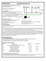
FRONT PANEL DESCRIPTION
NAME FUNCTION
1 Set value (SV) Comes on when the set value (SV)
indication lamp is displayed
2 Measured value (PV)/ Measured value (PV), Setpoint value (SV),
Set value (SV)/ or parameter symbols and codes are
parameter display displayed.
3 Select key To be used when the first, second, or
third block parameters are selected
4 UP key Pressing the key once will increase the
value by one. By pressing and holding it,
the value is continuously incremented.
5 DOWN key Pressing the key once will decrease the
value by one. By pressing and holding it,
the value is continuously decremented.
6 Autotuning indication Blinks while PID autotuning is being
lamp performed
7 Control output Comes on when the control output is ON
indication lamp
8 Alarm indication lamp Comes on when the alarm/second output
is activated. Blinks while the alarm is
being set.

17
FRONT PANEL OPERATION
The programming menu consists of three blocks— SETUP MENU,
SYSTEM MENU, and FACTORY PRESET MENU. At power up the controller
will be in the operational mode– process variable (PV) will be displayed.
This is the variable that is being controlled, and it is not programmable.
When setting the parameters, turn off the power to the load (operating
equipment) to ensure safety. Allow 30 minutes for the unit to stabilize in
terms of temperature, and to achieve the rated accuracy. Option-related
features are displayed only when the options are provided.
Viewing and Setting Parameters
• The data is automatically registered in 3 seconds after the setting.
It can also be registered by pressing the SEL key.
How to set Setpoint value (SV)
Operation Display
1. Power on – Process value (PV)
2. Press SEL key – SV value; SV lamp is lit
3. Press UP or DOWN key – SVvalue changes accordingly
4. Press SEL key to go back to – Process value (PV); SV lamp off
the operational mode
SETUP MENU
Operation Display
1. Operational mode – Process value (PV)
2. Press SEL key for 3 seconds – roFF
3. Press UP key to select – rrUn/rHLd
rrUn/rHLd, if necessary
4. Press SEL key once – ALM LEDblinks; AH data (for
units with alarm option)

18
5. Press SEL key to access the – AT 0, ......
next parameter
6. Press SEL key for 3 secs. – Operational mode
SYSTEM MENU
Operation Display
1. Operational mode – Process value
2. Press and hold SEL key – 3 seconds later, “roFF”
7 seconds later, “P”
3. Release and press SEL key again – “P” data
4. Press UP or DOWN key – “P” data changes accordingly
5. Press SEL key once – “P”
6. Press DOWN key to scroll down – “i”, “d”, ..... “Mod”
the menu
7. Press SEL key for 3 secs. – Operational mode
FACTORY PRESET MENU
Operation Display
1. Operational mode – Process value
2. Press and hold SEL key – 3 seconds later, “roFF”
7 seconds later, “P”
9 seconds later, “P-n1”
3. Release and press SEL key again – “P-n1” data
4. Press UP or DOWN key – “P-n1” data changed
5. Press SEL key once – “P-n1”
6. Press DOWN key to scroll down – “P-dF”, ........ “dSP7”
the menu
7. Press SEL key for 3 secs. – Operational mode
Please refer to Quick Reference guide for a listing of all the parameters.

19
CN4431 MODEL CONFIGURATION
MODEL DESCRIPTION
_________________________________________________________________
CN4431(*)-R1 1/16 DIN controller, relay output
CN4431(*)-D1 1/16 DIN controller, DC SSR driver output
CN4431(*)-F1 1/16 DIN controller, 4-20 mA DC output
_________________________________________________________________
* Specify TR for Thermocouple/RTD input or CV for current/voltage input
ALARM OPTION
_________________________________________________________________
-A 2A, SPST relay
_________________________________________________________________
LOW VOLTAGE POWER SUPPLY OPTION
_________________________________________________________________
-24V 24V AC/DC, 50/60 Hz
_________________________________________________________________

20
CN4431 SPECIFICATIONS
INPUT RANGE TABLE:
_________________________________________________________
Input Signal Input Range Input Range Remarks
(°C) (°F)
_________________________________________________________
Thermocouple*
J 0 ~ 800 32 ~ 1472 Cold Junction
K 0 ~ 1200 32 ~ 2192 compensating
R 0 ~ 1600 32 ~ 2912 function built-in
B 0 ~ 1800 32 ~ 3272
S 0 ~ 1600 32 ~ 2912
T -199 ~ 200 -328 ~ 392
T -150 ~ 400 -238 ~ 752
E -199 ~ 800 -328 ~ 1472
N 0 ~ 1300 32 ~ 2372
PL2 0 ~ 1300 32 ~ 2372
_________________________________________________________
RTD*
Pt100 -150 ~ 850 -238 ~ 1562 Allowable wiring
α= .00385 resistance 10 ohms
max (per wire).
_________________________________________________________
DC Voltage/
Current**
1-5V Scaling Range: -1999 to 9999 For current input, use
0-5V Engineering the 250Ω resistor to
4-20mA units obtain 1-5V DC or
0-20mA 0-5V DC input.
_________________________________________________________
* For TR models
** For CV models
See also the description for parameter P-n2 in the programming section, on
how to program for `a particular input.
/