Page is loading ...


The airFiber AF-11FX radio is designed for use with the airFiber X antenna model AF-
11G35*.
* Check your local/regional regulations for the antenna gain allowed for your application
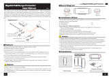
Installation Requirements
Clear line of sight between airFiber radios
Vertical mounting orientation
Mounting point:
At least 1 m below the highest point on the structure
For tower installations, at least 3 m below the top of the tower
Ground wires – min. 10 AWG (5 mm ) and max. length: 1 m. As a safety precaution,
ground the airFiber radio to grounded masts, poles, towers, or grounding bars.
WARNING: Failure to properly ground your airFiber radio will void your
warranty.
(Recommended) 2 Outdoor Gigabit PoE surge protectors
Note: For guidelines about grounding and lightning protection, follow your
local electrical regulatory codes.
High-Band Duplexer(s) (model AF-11FX-DUP-H) or Low-Band Duplexer(s) (model
AF-11FX-DUP-L) are required for proper operation:
SISO mode: One Duplexer of either band type
MIMO mode: Two Duplexers of the same band type
2
Note: Duplexers must be purchased separately. The Duplexer(s) must
match the terms of your license (frequency bands and polarities allowed).
Create PDF in your applications with the Pdfcrowd HTML to PDF API PDFCROWD


Chain 0 / Chain 1
Signal LEDs
Low-Band Duplexer High-Band Duplexer
When the Chain 0 or Chain 1 duplexer is installed, its N-type connector is located
here, allowing connection to an RF cable (Chain 1 is covered by the removable
duplexer cap).
Signal 4 LED will light blue when on.
Signal 3 LED will light green when on.
Signal 2 LED will light yellow when on.
Signal 1 LED will light red when on.
Bootup to airOS When powering on, the Power, MIMO, LINK, and Signal 1-4 LEDs
light on. Once the CPU code takes over, the MIMO, LINK, and Signal 1-3 LEDs turn
off. Signal 4 LED remains lit to indicate the boot sequence is underway.
Create PDF in your applications with the Pdfcrowd HTML to PDF API PDFCROWD

Link LED
Initializing airFiber Software When the airFiber application begins to boot under
airOS®, the Signal 4 LED goes from solidly on to a 2.5 Hz flash. This continues until
the AF‑11FX is fully booted.
Signal Level Once fully booted, the Signal 1-4 LEDs act as a bar graph showing how
close the AF‑11FX is to ideal aiming. This is auto-scaled based on the link range, the
antenna gains, and the configured TX power of the remote AF‑11FX. Each Signal
LED has three possible states: On, Flashing, and Off. All Signal LEDs would be
solidly on in an ideal link. For example, if the link has a 1 dB loss, the Signal 4 LED
will flash; a 2 dB loss and the Signal 4 LED will turn off. The full bar graph LED
states are shown below.
dB loss
0 -1 -2 -3 -4 -5 -6
-7 -8 -9 -10 -11 -12 -13
Off RF Off
Syncing
Create PDF in your applications with the Pdfcrowd HTML to PDF API PDFCROWD

MIMO LED
MGMT LED
Data LED
Power LED
Beaconing
Registering
On Operational
Off Radio Configured in SISO Mode
On Radio Configured in MIMO Mode
Off No Ethernet Link
On Ethernet Link Established
Random Flash Ethernet Activity
Off No Ethernet Link
On Ethernet Link Established
Random Flash Ethernet Activity
Off No Power
Create PDF in your applications with the Pdfcrowd HTML to PDF API PDFCROWD

Management Port
Reset Button
Data Port
VDC IN
TX 0, RX 0
RX 1, TX 1
On Powered On
10/100 Mbps, secured Ethernet port for configuration. In-Band Management is
enabled by default in the airFiber Configuration Interface. When In-Band
Management is disabled, the MGMT port is the only port that can monitor, configure,
and/or update firmware.
To reset to factory defaults, press and hold the Reset button for more than 10
seconds while the device is already powered on.
Gigabit PoE port for handling all user traffic and powering the device.
The terminal block can be used to power the AF-11FX with +50VDC, 1.2A instead of
PoE.
The TX and RX SMA ports for the Chain 0 Low-Band Duplexer or High-Band
Duplexer (SISO and MIMO modes).
The RX and TX SMA ports for the Chain 1 Low-Band Duplexer or High-Band
Duplexer (MIMO mode only). In SISO mode, these unused ports are protected by
Create PDF in your applications with the Pdfcrowd HTML to PDF API PDFCROWD

N Connector
SMA Port
the duplexer cap.
Female N-type connector into which the antenna cable is plugged.
High-band and low-band channel SMA ports.
Note: Duplexers are not included with the AF-11FX. SISO mode requires one
Low-Band Duplexer or one High-Band Duplexer. MIMO mode requires either
two Low-Band Duplexers or two High-Band Duplexers.
Installation Overview
We recommend that you configure your paired AF-11FX radios before site installation.
The overview below summarizes the installation procedure, and the subsequent
sections provide detailed installation information.
Install the Duplexer(s) in the AF-11FX radio.
Connect the airFiber Gigabit PoE adapter to the DATA port, and connect your
computer to the MGMT port.
Configure the AF-11FX.
Install a ground wire and mount the AF-11FX on the airFiber AF-11G35 antenna (or
a compatible antenna).
At the installation site, install the antenna with the mounted AF-11FX radio (see the
antenna’s Quick Start Guide for installation instructions).
Connect the DATA port to your LAN, and connect power (PoE or DC power) to the
AF-11FX.
Establish and optimize the RF link.
Create PDF in your applications with the Pdfcrowd HTML to PDF API PDFCROWD


5. Repeat steps 1-4 for the radio to be used on the other end of the link, ensuring that
the numbers on the second radio’s Duplexer are in the reverse order of the numbers
on first radio’s Duplexer.
Note: For example, if the numbers on the first radio’s Duplexer are (left to
right) 1/3, then the numbers on the second radio’s Duplexer should be 3/1.
Installing the Duplexers for MIMO Mode
Create PDF in your applications with the Pdfcrowd HTML to PDF API PDFCROWD


Note: Position the low channel and high channel ports to yield the required
transmit and receive frequencies. Also, ensure that the numbers on the right-
side Duplexer are in the reverse order of the numbers on the left-side
Duplexer.
3.
Create PDF in your applications with the Pdfcrowd HTML to PDF API PDFCROWD


6. Repeat steps 1-5 for the other radio to be used in the link, ensuring that the numbers
on the second radio’s Duplexers are in the reverse order of the numbers on the first
radio’s Duplexers.
Note: For example, if the numbers on the first radio’s Duplexers are (left to right)
2/4 and 4/2, the numbers on the second radio’s Duplexers should be 4/2 and
2/4.
Connecting Power over Ethernet
1.
Create PDF in your applications with the Pdfcrowd HTML to PDF API PDFCROWD
/