MIMAKI UJF-7151 plusII Operating instructions

Type
Operating instructions

This manual is also suitable for

OPT-J0521
- 1 -
© 2021 MIMAKI ENGINEERING CO.,LTD.
MDL Gateway Operation Manual
Thank you very much for purchasing the MDL Gateway. In order to use the product safely and correctly, please read
the instruction manual carefully and understand it thoroughly before use.
Accessories
If there is a shortage of parts or a problem, please contact your local distributor or MIMAKI sales office.
Name and function of each parts
Input/output cables are not included. Prepare the cable according to the customer's equipment specifications.
The input/output connector (37-pin D-sub connector) uses a clamping screw (Hirosugi DSB-7048DE clamp
section: M2.6).
Before using the MDL Gateway, be sure to read the instruction manual for the main unit.
What is “MDL commands”?
“MDL commands” are commands for enabling control of Mimaki’s printers using the user’s production system
and peripheral devices.
They make it possible to control the position and height of work setting tables and control printer operations
such as starting printing.
It is also possible to acquire the printer remaining ink quantity, error information, etc.
Concerning “MDL commands”, through utilizing technical information (SDK) provided by Mimaki to develop
software, it becomes possible to build the optimum system for the customer.
Information necessary for running “MDL commands, MDL Gateway” is distributed on the following dedicated
site as technical information (SDK).
https://mimaki.com/download/sdk/
User registration (free of charge) is required to download SDK.
MDL Gateway x1 Power cables x5
* Use a compatible power cable. LAN cable x1
Power switch:
Turn the switch to the "I" side to turn on
the power.
AC Inlet:
Plug in the power cable.
LAN port:
Connects to the main unit.
37-pin D-sub connector (Female):
Input port (IN)
37-pin D-sub connector (Female):
Output port (OUT)
- 2 -
© 2021 MIMAKI ENGINEERING CO.,LTD.
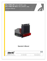
IO pin Internal circuit diagram
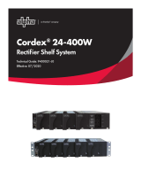
Input/output specifications for 37-pin D-sub connector
Model Number: DCSP-JB37SF, Manufacturer: JAE
* Signal names may be changed, added, or deleted.
Specifications
Pin No. Signal name (IN) Signal name (OUT) Pin No. Signal name (IN) Signal name (OUT)
1 Reserve Printer ready for operation 20 Reserve Reserve
2 Reserve printer linkage enabled state 21 Reserve Reserve
3 Automatic operation Acceptable for secondary work 22 Reserve Reserve
4 Reserve ready-to-print state 23 Reserve Reserve
5 Start printing / request During printing 24 Reserve Reserve
6 Pause / Request Error occurring 25 Reserve Reserve
7 Initialization / request Y-bar origin 26 Reserve Reserve
8 Cleaning / Request During Cleaning 27 Reserve Reserve
9 Table action/request Reservation 28 Reserve Reserve
10 Reserve Workpiece sensor status 29 Reserve Reserve
11 Reserve Low ink level information 30 Reserve Reserve
12 Reserve Cleaning in progress 31 Reserve Reserve
13 Data clear / request Table in operation 32 Reserve Reserve
14 Table vacuum switching /
request Table position 33 Reserve Reserve
15 Reserve Reserve 34 Reserve Reserve
16 Reserve Reserve 35 Reserve Reserve
17 (+)COM (-)COM 36 (+)COM (-)COM
18 N.C N.C 37 N.C N.C
19 N.C N.C
Power supply specifications AC100 to 240V ±10 % 50/60 Hz 1A max
Installation
environment Permissible ambient temperature 15 to 30 °C
Relative humidity 35 to 65 %RH (no condensation)
Temperature gradient Not more than ±10 °C/h
Dust Typical office
Maximum operating altitude 2,000 m
Weight 3.2 kg
External dimensions 282 x 183 x 173 mm
㼘㼛㼍㼐
㻼㼛㼣㼑㼞㻌㼟㼡㼜㼜㼘㼥㻌㼒㼛㼞㻌㼛㼡㼠㼜㼡㼠㻌㼏㼕㼞㼏㼡㼕㼠
㻔㻰㻯㻞㻠㼂㻕
㻵㼚㼟㼡㼘㼍㼠㼑㼐㻌㼜㼛㼣㼑㼞㻌㼟㼡㼜㼜㼘㼥
㻯㻻㻹
㻻㼁㼀
㻵㼚㼠㼑㼞㼚㼍㼘㻌㼏㼕㼞㼏㼡㼕㼠
㻼㼛㼣㼑㼞㻌㼟㼡㼜㼜㼘㼥㻌
㼒㼛㼞㻌㼕㼚㼜㼡㼠㻌㼏㼕㼞㼏㼡㼕㼠
㻔㻰㻯㻞㻠㼂㻕
㻵㼚㼠㼑㼞㼚㼍㼘㻌㼏㼕㼞㼏㼡㼕㼠
㻯㻻㻹
㻵㻺
㻡㻚㻢㼗䃈
㻠㻣㻜䃈
㻵㼚㼜㼡㼠㻌㼞㼍㼠㼕㼚㼓㻦㻌㻰㻯㻞㻠㼂㻛㻠㻚㻝㻭 㻾㼍㼠㼑㼐㻌㼘㼛㼍㼐㻦㻌㻰㻯㻟㻜㼂㻛㻜㻚㻞㻭
D203623-11-17122021 KM
  • Page 1 1
  • Page 2 2

MIMAKI UJF-7151 plusII Operating instructions

Type
Operating instructions
This manual is also suitable for

Ask a question and I''ll find the answer in the document

Finding information in a document is now easier with AI