
Your Power Solutions Partner
Cordex 48-650W Integrated Shelf System
Installation & Operation Manual
Part #CXS-650W-J0
Effective: 06/2017
member of The Group
™


Cordex 48-650W Integrated Shelf System Manual
NOTE: Photographs contained in this manual are for illustrative purposes only. These photographs may
not match your installation.
NOTE: Operator is cautioned to review the drawings and illustrations contained in this manual before
proceeding. If there are questions regarding the safe operation of this powering system, contact Alpha
Technologies or your nearest Alpha representative.
NOTE: Alpha shall not be held liable for any damage or injury involving its enclosures, power supplies,
generators, batteries, or other hardware if used or operated in any manner or subject to any condition
inconsistent with its intended purpose, or if installed or operated in an unapproved manner, or improp-
erly maintained.
Copyright
Copyright © 2017 Alpha Technologies Ltd. All rights reserved. Alpha is a registered
trademark of Alpha Technologies.
No part of this documentation shall be reproduced, stored in a retrieval system, translated, transcribed,
or transmitted in any form or by any means manual, electric, electronic, electromechanical, chemical,
optical, or other-wise without prior explicit written permission from Alpha Technologies.
This document, the software it describes, and the information and know-how they contain constitute the
proprietary, confidential and valuable trade secret information of Alpha Technologies, and may not be
used for any unauthorized purpose, or disclosed to others without the prior written permission of Alpha
Technologies.
The material contained in this document is for information only and is subject to change without notice.
While reasonable efforts have been made in the preparation of this document to assure its accuracy,
Alpha Technologies assumes no liability resulting from errors or omissions in this document, or from the
use of the information contained herein. Alpha Technologies reserves the right to make changes in the
product design without reservation and without notification to its users.
)RUWHFKQLFDOVXSSRUWFRQWDFW$OSKD7HFKQRORJLHV
&DQDGDDQG86$
,QWHUQDWLRQDO


i
TABLE OF CONTENTS
1SAFETY . . . . . . . . . . . . . . . . . . . . . . . . . . . . . . . . . . . . . 1
Safety Wording/Symbols . . . . . . . . . . . . . . . . . . . . . . . . . . . . 1
General Warning and Cautions . . . . . . . . . . . . . . . . . . . . . . . . . 1
Electrical Safety . . . . . . . . . . . . . . . . . . . . . . . . . . . . . . . . . 1
Battery Safety . . . . . . . . . . . . . . . . . . . . . . . . . . . . . . . . . . 2
2I
NTRODUCTION . . . . . . . . . . . . . . . . . . . . . . . . . . . . . . . . . . 5
Scope . . . . . . . . . . . . . . . . . . . . . . . . . . . . . . . . . . . . . . 5
Product Overview . . . . . . . . . . . . . . . . . . . . . . . . . . . . . . . . 5
3F
EATURES . . . . . . . . . . . . . . . . . . . . . . . . . . . . . . . . . . . . 7
Rectifier . . . . . . . . . . . . . . . . . . . . . . . . . . . . . . . . . . . . . 7
Rectifier Front Panel . . . . . . . . . . . . . . . . . . . . . . . . . . . . . 7
LEDs . . . . . . . . . . . . . . . . . . . . . . . . . . . . . . . . . . . . . 7
Mechanical . . . . . . . . . . . . . . . . . . . . . . . . . . . . . . . . . . 8
True Module Fail Alarm . . . . . . . . . . . . . . . . . . . . . . . . . . . 8
Heat Dissipation . . . . . . . . . . . . . . . . . . . . . . . . . . . . . . . 8
Over Temperature Protection . . . . . . . . . . . . . . . . . . . . . . . . 8
Wide AC Range . . . . . . . . . . . . . . . . . . . . . . . . . . . . . . . 8
AC Inrush/Transient Suppression . . . . . . . . . . . . . . . . . . . . . . 8
Soft Start . . . . . . . . . . . . . . . . . . . . . . . . . . . . . . . . . . . 9
Start Delay . . . . . . . . . . . . . . . . . . . . . . . . . . . . . . . . . . 9
Current Limit/Short Circuit Protection . . . . . . . . . . . . . . . . . . . . 9
Power Limiting . . . . . . . . . . . . . . . . . . . . . . . . . . . . . . . . 9
High Voltage Shutdown (HVSD) . . . . . . . . . . . . . . . . . . . . . . . 9
Battery Eliminator Operation . . . . . . . . . . . . . . . . . . . . . . . . . 9
Overview of the CXCI HP . . . . . . . . . . . . . . . . . . . . . . . . . . . . 10
Display . . . . . . . . . . . . . . . . . . . . . . . . . . . . . . . . . . . . 10
In-Shelf Display: Menu . . . . . . . . . . . . . . . . . . . . . . . . . . . . 11
In-Shelf Controller Buttons . . . . . . . . . . . . . . . . . . . . . . . . . . 12
Overview of the CXCI+ . . . . . . . . . . . . . . . . . . . . . . . . . . . . . 12
LEDs . . . . . . . . . . . . . . . . . . . . . . . . . . . . . . . . . . . . . 13
Reset (CXCI+ only) . . . . . . . . . . . . . . . . . . . . . . . . . . . . . 14
Controller Input and Output . . . . . . . . . . . . . . . . . . . . . . . . . . . 14
Ethernet Port . . . . . . . . . . . . . . . . . . . . . . . . . . . . . . . . . 14
Analog Input Channels . . . . . . . . . . . . . . . . . . . . . . . . . . . 14
Digital Input Channels . . . . . . . . . . . . . . . . . . . . . . . . . . . . 14
Alarm and Control Output Relays . . . . . . . . . . . . . . . . . . . . . . 14
Network Connection and Remote Communication . . . . . . . . . . . . . 15
Controller Connections . . . . . . . . . . . . . . . . . . . . . . . . . . . 15
4I
NSPECTION . . . . . . . . . . . . . . . . . . . . . . . . . . . . . . . . . . . 17

ii
Check for Damage . . . . . . . . . . . . . . . . . . . . . . . . . . . . . . . 17
Packing Materials . . . . . . . . . . . . . . . . . . . . . . . . . . . . . . . . 17
Returns for Service . . . . . . . . . . . . . . . . . . . . . . . . . . . . . . . 17
5I
NSTALLATION . . . . . . . . . . . . . . . . . . . . . . . . . . . . . . . . . . 19
Installation . . . . . . . . . . . . . . . . . . . . . . . . . . . . . . . . . . . . 19
Safety Precautions . . . . . . . . . . . . . . . . . . . . . . . . . . . . . . 19
Shelf Preparation/Mounting . . . . . . . . . . . . . . . . . . . . . . . . . 19
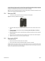
Module Insertion/Removal . . . . . . . . . . . . . . . . . . . . . . . . . . 19
Removing a CXRC . . . . . . . . . . . . . . . . . . . . . . . . . . . . . 20
Removing the CXCI HP . . . . . . . . . . . . . . . . . . . . . . . . . . . 20
6W
IRING AND CONNECTIONS . . . . . . . . . . . . . . . . . . . . . . . . . . . . 23
Safety Precautions . . . . . . . . . . . . . . . . . . . . . . . . . . . . . . . 23
Tools Required . . . . . . . . . . . . . . . . . . . . . . . . . . . . . . . . . 23
Power System Chassis Ground and DC Ground . . . . . . . . . . . . . . . . 23
AC Feeder Protection/Sizing . . . . . . . . . . . . . . . . . . . . . . . . . . 23
AC Input . . . . . . . . . . . . . . . . . . . . . . . . . . . . . . . . . . . . . 24
Calculating Output Wire Size Requirements . . . . . . . . . . . . . . . . . . 24
DC Output . . . . . . . . . . . . . . . . . . . . . . . . . . . . . . . . . . . . 25
Circuit Breaker Distribution . . . . . . . . . . . . . . . . . . . . . . . . . 25
CAN Ports . . . . . . . . . . . . . . . . . . . . . . . . . . . . . . . . . . . . 25
Network Connection and Remote Communications via CXC . . . . . . . . . . 25
Ethernet Port for Network Connection . . . . . . . . . . . . . . . . . . . . 25
Ethernet Port for Local Connection . . . . . . . . . . . . . . . . . . . . . 26
Signal Wiring Connections . . . . . . . . . . . . . . . . . . . . . . . . . . . 26
Analog Inputs . . . . . . . . . . . . . . . . . . . . . . . . . . . . . . . . 27
Digital Inputs . . . . . . . . . . . . . . . . . . . . . . . . . . . . . . . . . 27
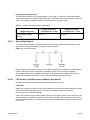
Alarm Relay Outputs . . . . . . . . . . . . . . . . . . . . . . . . . . . . . 28
LVD Control (Load Disconnect or Battery Disconnect) . . . . . . . . . . . 28
LVD Control Alternative . . . . . . . . . . . . . . . . . . . . . . . . . . . 29
7O
PERATION . . . . . . . . . . . . . . . . . . . . . . . . . . . . . . . . . . . 31
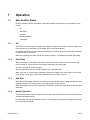
Main Rectifier States . . . . . . . . . . . . . . . . . . . . . . . . . . . . . . 31
Off . . . . . . . . . . . . . . . . . . . . . . . . . . . . . . . . . . . . . . 31
Start Delay . . . . . . . . . . . . . . . . . . . . . . . . . . . . . . . . . . 31
Soft Start . . . . . . . . . . . . . . . . . . . . . . . . . . . . . . . . . . . 31
Normal Operation . . . . . . . . . . . . . . . . . . . . . . . . . . . . . . 31
Turning Off . . . . . . . . . . . . . . . . . . . . . . . . . . . . . . . . . . 32
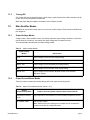
Main Rectifier Modes . . . . . . . . . . . . . . . . . . . . . . . . . . . . . . 32
Output Voltage Modes . . . . . . . . . . . . . . . . . . . . . . . . . . . . 32
Output Current/Power Modes . . . . . . . . . . . . . . . . . . . . . . . . 32
Can Bus Communication . . . . . . . . . . . . . . . . . . . . . . . . . . . . 33
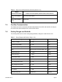
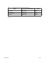
Factory Ranges and Defaults . . . . . . . . . . . . . . . . . . . . . . . . . . 33

iii
8SYSTEM STARTUP . . . . . . . . . . . . . . . . . . . . . . . . . . . . . . . . 35
Check System Connections . . . . . . . . . . . . . . . . . . . . . . . . . . . 35
Verify AC and Power The Shelf . . . . . . . . . . . . . . . . . . . . . . . . . 35
Check Battery Polarity and Connect . . . . . . . . . . . . . . . . . . . . . . 35
Controller Reset . . . . . . . . . . . . . . . . . . . . . . . . . . . . . . . . . 35
Soft Reset (CXCI+ only) . . . . . . . . . . . . . . . . . . . . . . . . . . . 35
IP Address Reset (CXCI+ only) . . . . . . . . . . . . . . . . . . . . . . . 36
Hard Reset . . . . . . . . . . . . . . . . . . . . . . . . . . . . . . . . . . 36
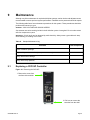
9M
AINTENANCE . . . . . . . . . . . . . . . . . . . . . . . . . . . . . . . . . . 37
Replacing a CXCI HP Controller . . . . . . . . . . . . . . . . . . . . . . . . 37
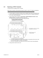
Replacing a CXCI+ Controller . . . . . . . . . . . . . . . . . . . . . . . . . . 38
10 W
ARRANTY AND SERVICE INFORMATION . . . . . . . . . . . . . . . . . . . . . 41
Technical Support . . . . . . . . . . . . . . . . . . . . . . . . . . . . . . . . 41
Warranty Statement . . . . . . . . . . . . . . . . . . . . . . . . . . . . . . . 41
Product Warranty . . . . . . . . . . . . . . . . . . . . . . . . . . . . . . . . 41
Battery Warranty . . . . . . . . . . . . . . . . . . . . . . . . . . . . . . . . 41
Warranty Claims . . . . . . . . . . . . . . . . . . . . . . . . . . . . . . . . . 41
Service Information . . . . . . . . . . . . . . . . . . . . . . . . . . . . . . . 41
11 C
ERTIFICATION . . . . . . . . . . . . . . . . . . . . . . . . . . . . . . . . . . 43
12 G
LOSSARY . . . . . . . . . . . . . . . . . . . . . . . . . . . . . . . . . . . . 45
13 S
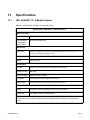
PECIFICATIONS . . . . . . . . . . . . . . . . . . . . . . . . . . . . . . . . . 47
2RU, 48-650W, 19”, 4-Module System . . . . . . . . . . . . . . . . . . . . . 47
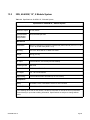
2RU, 48-650W, 19”, 5 Module System . . . . . . . . . . . . . . . . . . . . . 48
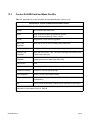
Cordex 48-650W Switched Mode Rectifier . . . . . . . . . . . . . . . . . . . 49
CXCI HP Controller . . . . . . . . . . . . . . . . . . . . . . . . . . . . . . . 52
CXCI+ Controller . . . . . . . . . . . . . . . . . . . . . . . . . . . . . . . . 54

iv
LIST OF FIGURES
Figure 1: Four Module, 030-728 . . . . . . . . . . . . . . . . . . . . . . . . . . . . 6
Figure 2: Five Module, 030-782. . . . . . . . . . . . . . . . . . . . . . . . . . . . . 6
Figure 3: Rectifier Front Panel . . . . . . . . . . . . . . . . . . . . . . . . . . . . . 7
Figure 4: CXCI HP Controller . . . . . . . . . . . . . . . . . . . . . . . . . . . . .10
Figure 5: In-Shelf Controller Dashboard Screens. . . . . . . . . . . . . . . . . . . .11
Figure 6: In-Shelf Controller Menu . . . . . . . . . . . . . . . . . . . . . . . . . . .11
Figure 7: In-Shelf Controller Buttons . . . . . . . . . . . . . . . . . . . . . . . . . .12
Figure 8: Cordex CXCI+ model system controller front panel . . . . . . . . . . . . .13
Figure 9: Packing Materials and Environmental Codes . . . . . . . . . . . . . . . .17
Figure 10: Removing a Rectifier from the Shelf . . . . . . . . . . . . . . . . . . . . .20
Figure 11: Removing the CXCI HP . . . . . . . . . . . . . . . . . . . . . . . . . . .21
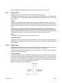
Figure 12: Digital Input Connection Method . . . . . . . . . . . . . . . . . . . . . . .27
Figure 13: Relay Connections . . . . . . . . . . . . . . . . . . . . . . . . . . . . . .28
Figure 14: Removing the CXCI HP. . . . . . . . . . . . . . . . . . . . . . . . . . . .37

v
LIST OF TABLES
Table 1: In-Shelf Controller Full Menu . . . . . . . . . . . . . . . . . . . . . . . . .11
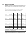
Table 2: Recommended AC Supply Configuration. . . . . . . . . . . . . . . . . . .24
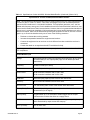
Table 3: Wiring Connections for the CXCI Series of Controllers. . . . . . . . . . . .26
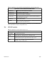
Table 4: Voltage Level Definitions for Digital Inputs . . . . . . . . . . . . . . . . . .28
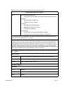
Table 5: Output Voltage Modes . . . . . . . . . . . . . . . . . . . . . . . . . . . .32
Table 6: Output Current/Power Modes. . . . . . . . . . . . . . . . . . . . . . . . .32
Table 7: Factory Ranges and Defaults. . . . . . . . . . . . . . . . . . . . . . . . .33
Table 8: Sample Maintenance Log. . . . . . . . . . . . . . . . . . . . . . . . . . .37
Table 9: Specifications: 48-650W 19”, 4 Module System . . . . . . . . . . . . . . .47
Table 10: Specifications: 48-650W 19”, 5 Module System . . . . . . . . . . . . . . .48
Table 11: Specifications: Cordex 48-650W, Switched Mode Rectifier . . . . . . . . .49
Table 12: Specifications: CXCI HP Controller . . . . . . . . . . . . . . . . . . . . . .52

vi

CXS-650W-J0 Rev A Page 1
1 Safety
SAVE THESE INSTRUCTIONS: This manual contains important safety instructions that must be
followed during the installation, servicing, and maintenance of the product. Keep it in a safe place.
Review the drawings and illustrations contained in this manual before proceeding. If there are any ques-
tions regarding the safe installation or operation of this product, contact Alpha Technologies or the
nearest Alpha representative.
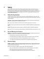
1.1 Safety Wording/Symbols
To reduce the risk of injury or death, and to ensure the continued safe operation of this product, the
following symbols have been placed throughout this manual. Where these symbols appear, use extra
care and attention.
ATTENTION: The use of attention indicates specific regulatory/code requirements that may affect the
placement of equipment and /or installation procedures.
NOTE: Notes provide additional information to help complete a specific task or procedure.
CAUTION: Cautions indicate safety information intended to PREVENT DAMAGE to material or equip-
ment.
WARNING: Warnings present safety information to PREVENT INJURY OR DEATH to personnel.
NOTE: HOT! The use of Hot presents safety information to PREVENT BURNS to the technician or user.
1.2 General Warning and Cautions
WARNING: You must read and understand the following warnings before installing the system and its
components. Failure to do so could result in personal injury or death.
• Read and follow all instructions included in this manual.
• Only trained personnel are qualified to install or replace this equipment and its components.
• Use proper lifting techniques whenever handling equipment, parts, or batteries.
• To be installed in a restricted access location that is inaccessible to the general public.
1.3 Electrical Safety
WARNING: Hazardous voltages are present at the input of power systems. The DC output from some
rectifiers and batteries can have high voltage and high short-circuit current capacity that may cause
severe burns and electrical arcing.
Before working with any live battery or power system, follow these precautions:
• Remove all metallic jewelry, such as watches, rings, metal rimmed glasses, or necklaces.
• Wear safety glasses with side shields at all times during the installation.
• Use OSHA approved insulated hand tools. Do not rest tools on top of batteries.

CXS-650W-J0 Rev A Page 2
WARNING: Lethal voltages are present within the power system. Always assume that an electrical
connection or conductor is energized. Check the circuit with a voltmeter with respect to the grounded
portion of the enclosure (both AC and DC) before performing any installation or removal procedure.
• Do not work alone under hazardous conditions.
• A licensed electrician is required to install permanently wired equipment. Input voltages can range
up to 240Vac. Ensure that the utility power is disconnected and locked out before performing any
installation or removal procedure.
• Ensure that no liquids or wet clothes come into contact with internal components.
• Hazardous electrically live parts inside this unit are energized from the batteries even when the
AC input power is disconnected.
• The enclosure which contains the DC or AC power system along with customer installed radios
must remain locked at all times, except when authorized service personnel are present.
• Always assume electrical connections or conductors are live. Turn off all circuit breakers and
double-check with a voltmeter before performing installation or maintenance.
• Place a warning label on the utility panel to warn emergency personnel that a reserve battery
source is present which will power the loads in a power outage condition or if the AC disconnect
breaker is turned off.
• At high ambient temperature conditions, the internal temperature can be hot so use caution when
touching the equipment.
WARNING: The intra-building ports (Ethernet, CAN, Alarm relays) of the equipment or subassembly are
suitable for connection to intra-building or unexposed wiring or cabling only. The intra-building ports of
the equipment or subassembly MUST NOT be metallically connected to interfaces that connect to the
OSP or its wiring. These interfaces are designed for use as intra-building interfaces only (Type 2 or Type
4 ports) and require isolation from the exposed OSP cabling. The addition of Primary Protectors is not
sufficient protection in order to connect these interfaces metallically to OSP wiring.
WARNING: Controller Ethernet port is not designed to withstand lightning and AC power cross surges
according to the NEBS requirements in GR-1089-CORE. Ensure that any Ethernet cable used (not
provided by Alpha) does not exceed a maximum length of 6 meters.
1.4 Battery Safety
• Never transport an enclosure with batteries installed. Batteries must ONLY be installed after the
enclosure has been securely set in place at its permanent installation location. Transporting the
unit with batteries installed may cause a short circuit, fire, explosion, and/or damage to the battery
pack, enclosure and installed equipment.
• Servicing and connection of batteries must be performed by, or under the direct supervision of,
personnel knowledgeable of batteries and the required safety precautions.
• Batteries contain or emit chemicals known to cause cancer and birth defects or other reproductive
harm. Battery post terminals and related accessories contain lead and lead compounds. Wash
your hands after handling batteries.
WARNING: Follow battery manufacturer’s safety recommendations when working around battery
systems. Do not smoke or introduce an open flame when batteries (especially vented batteries) are
charging. When charging, batteries vent hydrogen gas, which can explode.

CXS-650W-J0 Rev A Page 3
• Batteries are hazardous to the environment and should be disposed at a recycling facility. Consult
the battery manufacturer for recommended local authorized recyclers.

CXS-650W-J0 Rev A Page 4

CXS-650W-J0 Rev A Page 5
2 Introduction
2.1 Scope
This manual explains the installation, interconnection, and operation of the following Alpha Technolo-
gies shelf systems:
• Cordex 48-650W integrated 19" 2RU shelf system with up to 2600W output power and distribu-
tion.
• Cordex 48-650W integrated 19" 2RU shelf system with up to 3250W output power and distribu-
tion.
2.2 Product Overview
A complete Alpha Technologies Cordex rectifier system consists of a controller with one or more power
modules in a common shelf enclosure. The shelf has connections for AC inputs, DC output, and system
communications.
Cordex rectifier modules use a high frequency, switched mode conversion technique to provide a fully
regulated and isolated DC output from the AC mains. The Cordex 48-650W rectifier system, model
010-570-20 is universal for use on 120/208/220/240Vac 50/60Hz electrical service.
Rectifier power modules are “hot swappable” meaning they can be inserted or removed from the shelf
without cutting power to or from the system or the load. Additional power modules can be included with
the system at the time of ordering or added after the shelf has been installed.
The shelf rectifier system is designed to operate with the Alpha CXCI series of controllers (includes
CXCI+ and CXCI HP); which is built into the rectifier system shelf. Details for installation and wiring are
provided in the respective chapters of this documentation.
All models of the controller allow the user to set up, control and monitor the entire power system and its
components from one central, easy-to-use source: your web browser. The CXCI+ model does not have
a touch screen display; therefore, system setup and management is performed exclusively with the web
interface. Details of controller operation are provided in the current version software manual.
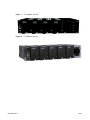
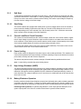
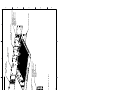
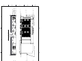
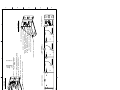
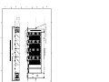
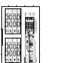
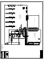
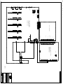
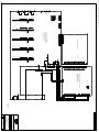
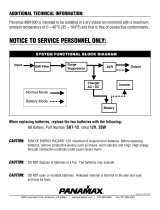
The following figures are examples of:
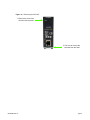
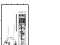
1. Cordex 48-650W integrated 19" 2RU shelf system: The distribution component utilizes four
bullet-type breakers.
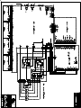
2. Cordex 48-650W integrated 19” 2RU: The optional distribution component utilizes one AM-style
breaker.

CXS-650W-J0 Rev A Page 6
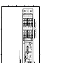
Figure 1: Four Module, 030-728
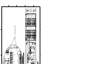
Figure 2: Five Module, 030-782

CXS-650W-J0 Rev A Page 7
3 Features
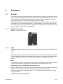
3.1 Rectifier
The Cordex CXRC series of 48V 650W rectifier modules employ an advanced resonant power conver-
sion technology featuring high power conversion efficiency. All internal semiconductor devices operate
under “soft-switching” conditions and exhibit very low power loss. The reduced power loss leads to
lower thermal stress on the semiconductors and thus improves reliability.
Sustaining low component temperatures is again the primary factor with meeting the three worst-case
field scenarios: (1) 65°C ambient temperatures, (2) full output power, and (3) low AC input (176Vac).
While meeting these specifications, Cordex rectifiers also offer roughly twice the reliability at 55°C and
up to four times more at 45°C ambient temperature.
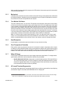
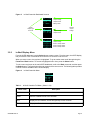
3.1.1 Rectifier Front Panel
Figure 3: Rectifier Front Panel
3.1.2 LEDs
The front panel LEDs provide rectifier status summary and help to locate a specific module under CXC
control.
OK
The top LED (green) is on when AC is within valid range and the rectifier is delivering power to the load.
The LED will flash (~2Hz) when AC is outside the nominal range – AC voltage is invalid if the AC Mains
Low or AC Mains High alarm is active. The LED turns off when AC has failed (or no AC power is
present).
Alarm
The bottom LED (red) is on continuously in the event of an active Module Fail alarm. The LED flashes
(~2Hz) when a minor alarm is detected. The LED remains off in the absence of an alarm.
LED Activity During “Locate Module” Command from CXC
When the “locate module” command has been received from the CXC, the LEDs behave in a distinctly
different way so that the rectifier is easier to visually identify among adjacent rectifiers.
This state is entered when commanded via the CXC. The LEDs flash in a distinct pattern repeating
every two seconds.
LED Activity During Firmware Upload

CXS-650W-J0 Rev A Page 8
When a rectifier firmware upload is in progress, the LEDs behave in the same way as the locate module
command described above.
3.1.3 Mechanical
A thumbscrew is provided to secure the rectifier into the shelf. During normal operation the rectifier shall
be locked into position. A handle (or grip) is incorporated into the front panel to facilitate the removal of
the rectifier from the shelf. No special tools are required.
3.1.4 True Module Fail Alarm
The power modules have a “true” fail alarm. This provides a true indication of the power module’s ability
to source current. When the module’s output current drops below 2.5% of the rated output a low output
current condition is detected and the Module Fail detection circuit is activated. This circuit momentarily
ramps up the output voltage to determine if the module will source current. If no increase in current is
detected, the Module Fail alarm is activated. The module will test once every 60 seconds for the condi-
tion until current is detected. Output voltage ramping will cease upon detection of current
1
. A minimum
2.5% load is required to avoid the Ramp Test Fail alarm; this can typically be provided with the parallel
system battery. Activation of this alarm could indicate a failed module or a failed load.
NOTE: For Cordex rectifier systems without batteries (or with a very light load; below 2.5% of rated
output) it is recommended that the ramp test be disabled to avoid nuisance alarms. The Ramp Test
feature is enabled/disabled via the controller. Refer to the software manual for detailed information.
3.1.5 Heat Dissipation
Heat dissipation is achieved through natural (bottom to top) convection cooling
3.1.6 Over Temperature Protection
Each rectifier module is protected in the event of an excessive increase in temperature due to compo-
nent failure or cooling airflow blockage. During over temperature conditions, the rectifier limits the output
power as well as the output current. If temperature continues to increase, a shutdown of the rectifier is
initiated. The rectifier shall restart automatically if the temperature has returned to a safe level.
3.1.7 Wide AC Range
A minor alarm is generated when the AC input voltage drops below specification. For voltages above
specifications, power factor and total harmonic distortion may be derated.
• Rectifier Module #010-570-20: Output power is reduced linearly between 176Vac and 90Vac to
75% of the rated output power. At a lower voltage the module will shutdown and will not restart
until the AC is greater than 100Vac. For voltages between 276Vac and 320Vac, the rectifier may
not be operational but shall not suffer any damage.
3.1.8 AC Inrush/Transient Suppression
An external surge suppressor is not required at the AC input, modules are protected from input lightning
and transient surges in accordance with IEEE/ANSI C62.41 Category B3.
1. Under normal conditions, a battery connected to the output of the rectifier will draw current when the voltage
ramp occurs. Therefore the rectifier fail alarm will not be generated with a battery connected.

CXS-650W-J0 Rev A Page 9
3.1.9 Soft Start
To eliminate an instantaneous demand on the AC source, a soft start feature is employed. Soft Start,
sometimes referred to as “current walk-in”, works by gradually (up to five seconds) ramping the current
limit up from zero to the actual or defined customer setting. The rectifier output voltage is ramped up
from the minimum voltage to the float voltage.
3.1.10 Start Delay
The rectifier modules are equipped with a delay timer in order to stagger start a series of modules to
prevent excessive loading of generators upon start up. The built-in timer delays the turn on of the
module depending on the value selected (up to 120 seconds) via the CXC. A minimum one-second
delay is preset to allow charging of the input capacitors.
3.1.11 Current Limit/Short Circuit Protection
The current limit function determines the maximum output current limit of the rectifier module, regard-
less of output voltage or power. Maximum output current is limited to a constant value down to short
circuit condition. Current limiting can be used to mate the rectifier output current ampacity to the needs
of the load and parallel battery to minimize excessive battery recharge current.
The rectifier will sustain a short circuit at the output terminals indefinitely. The maximum short circuit
current cannot exceed 105% of the rated full load current.
3.1.12 Power Limiting
Each rectifier module is designed to limit power output to the module specification. This enables more
current to be supplied at lower output voltages, and allows matching of output to the demand of constant
power loads, normally seen with telecom equipment.
This feature may also be used for a faster recharge of flooded batteries paralleled with the load.
NOTE: Current limiting overrides the power-limiting feature.
3.1.13 High Voltage Shutdown (HVSD)
This feature provides protection to the load from over voltage conditions originating from the rectifiers.
It operates by shutting down the offending rectifier module when a high output voltage condition occurs.
Indication is through the red Alarm (Module Fail) LED. Modules will restart automatically; however, if
more than three over voltage conditions occur in one minute, the module will latch off and remain shut
down until it is reset.
3.1.14 Battery Eliminator Operation
Rectifier modules maintain all specifications (except where indicated) with or without a battery attached
in parallel to the output; however, if a battery or another module supplying DC voltage in parallel is not
present, there will be no monitoring or control activity if there is an AC power failure or input fuse failure.
Paralleling Diode (optional): An optional Oring MOSFET on the output prevents disruption of DC
system output power in the event of a rectifier internal fault in systems without batteries.

CXS-650W-J0 Rev A Page 10
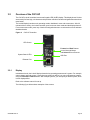
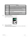
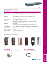
3.2 Overview of the CXCI HP
The CXC HP in-shelf controllers have a small organic LED (OLED) display. This display shows 30 char-
acters total (five lines high, six characters wide) and the controller has three navigation buttons and one
reset button.
The in-shelf display has three main operating modes: dashboard, menu and screen saver. After 20
minutes with no activity, the in-shelf controller goes into screen saver mode and the display shuts off.
From screen saver mode, press any of the three navigation buttons to re-activate the screen and enter
dashboard mode.
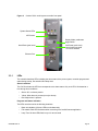
Figure 4: CXCI HP Controller
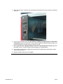
3.2.1 Display
In dashboard mode, the in-shelf display shows the key operating parameters of a system. For example,
output voltage and load current. If more than one system is defined, you can cycle between systems
using the Forward and Back buttons. With multiple systems, you can specify a default system, which
is then displayed first.
Refer to the software manual for set up.
The following figure below shows examples of the screens.
System Status LEDs
LED Screen
Forward and Back Buttons
to scroll through Menus
and Select button to Execute
Ethernet Port
USB Port
Page is loading ...
Page is loading ...
Page is loading ...
Page is loading ...
Page is loading ...
Page is loading ...
Page is loading ...
Page is loading ...
Page is loading ...
Page is loading ...
Page is loading ...
Page is loading ...
Page is loading ...
Page is loading ...
Page is loading ...
Page is loading ...
Page is loading ...
Page is loading ...
Page is loading ...
Page is loading ...
Page is loading ...
Page is loading ...
Page is loading ...
Page is loading ...
Page is loading ...
Page is loading ...
Page is loading ...
Page is loading ...
Page is loading ...
Page is loading ...
Page is loading ...
Page is loading ...
Page is loading ...
Page is loading ...
Page is loading ...
Page is loading ...
Page is loading ...
Page is loading ...
Page is loading ...
Page is loading ...
Page is loading ...
Page is loading ...
Page is loading ...
Page is loading ...
Page is loading ...
Page is loading ...
Page is loading ...
Page is loading ...
Page is loading ...
Page is loading ...
Page is loading ...
Page is loading ...
Page is loading ...
Page is loading ...
Page is loading ...
Page is loading ...
Page is loading ...
Page is loading ...
Page is loading ...
Page is loading ...
Page is loading ...
Page is loading ...
Page is loading ...
Page is loading ...
-
 1
1
-
 2
2
-
 3
3
-
 4
4
-
 5
5
-
 6
6
-
 7
7
-
 8
8
-
 9
9
-
 10
10
-
 11
11
-
 12
12
-
 13
13
-
 14
14
-
 15
15
-
 16
16
-
 17
17
-
 18
18
-
 19
19
-
 20
20
-
 21
21
-
 22
22
-
 23
23
-
 24
24
-
 25
25
-
 26
26
-
 27
27
-
 28
28
-
 29
29
-
 30
30
-
 31
31
-
 32
32
-
 33
33
-
 34
34
-
 35
35
-
 36
36
-
 37
37
-
 38
38
-
 39
39
-
 40
40
-
 41
41
-
 42
42
-
 43
43
-
 44
44
-
 45
45
-
 46
46
-
 47
47
-
 48
48
-
 49
49
-
 50
50
-
 51
51
-
 52
52
-
 53
53
-
 54
54
-
 55
55
-
 56
56
-
 57
57
-
 58
58
-
 59
59
-
 60
60
-
 61
61
-
 62
62
-
 63
63
-
 64
64
-
 65
65
-
 66
66
-
 67
67
-
 68
68
-
 69
69
-
 70
70
-
 71
71
-
 72
72
-
 73
73
-
 74
74
-
 75
75
-
 76
76
-
 77
77
-
 78
78
-
 79
79
-
 80
80
-
 81
81
-
 82
82
-
 83
83
-
 84
84


Alpha Cordex 030-728 Installation & Operation Manual
- Type
- Installation & Operation Manual
- This manual is also suitable for
Ask a question and I''ll find the answer in the document
Finding information in a document is now easier with AI
Related papers
-
Alpha Cordex CXC HP User guide
-
Alpha Cordex™ CXCM Owner's manual
-
-
-
-
-
-
Alpha Cordex CXPS-HSS User manual
-
-
Other documents
-
 Alpha Technologies Cordex 24 User manual
-
FSR VWP-SVA-SF Owner's manual
-
 Panamax MB1000 User manual
-
Tyco CPS6000 User manual
-
ICT Digital Series 2 Owner's manual
-
Christie FHD553-XE-HR Owner's manual
-
3M Cold Shrink Coax Sealing Kit CXS-2 Operating instructions
-
SEI DC-UPS Series User manual
-
 OPTI-UPS Standby UPS System User manual
-
Mitsubishi Electric PAC-YT53CRAU Installation guide


