Page is loading ...

CA20 Combine Adaptor
SPROCKET INSTALLATION INSTRUCTIONS
Form # 169035 Rev C. Page 1 of 2
CAUTION Stop engine and remove key from ignition before leaving operator's seat for
any reason. A child or even a pet could engage an idling machine.
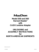
1. Drain gearbox oil and remove cover:
a. Rotate gearbox to position oil level plug (N) at
the lowest point as follows: Detach brace from
gearbox, loosen top pivot bolt and move out of
field position to transport position. Remove oil
level plug (N) to drain the oil.
b. Not all oil can be drained through the oil
level plug therefore remove gearbox
cover and clamp plate hardware (A)
starting at the bottom and working up. To
avoid cover possibly falling off, do not
remove upper set of hardware (B).
c. Pry open bottom of plastic cover to drain
the remaining oil.
Note: There is a rubber gasket
between the gearbox and cover. Do
not damage gasket when removing
cover.
d. Once oil has been drained, remove
remaining cover hardware (B), clamp
plate (C) and plastic cover (D).
2. Remove roller chain:
a. Remove oil fill plug (E).
b. Remove spring and retaining clip (F).
c. Loosen chain tensioning bolt (G) and
remove chain.
3. Remove driveline sprocket:
a. Temporally fix driveline from rotating
when removing sprocket hardware by
inserting a bar (H) through the u-joint as
shown.
A
B
E
F
CA20 GEARBOX ASSEMBLY
G
C
D
DRIVELINE U-JOINT
H
N

CA20 Combine Adaptor
SPROCKET INSTALLATION INSTRUCTIONS
Form # 169035 Rev C. Page 2 of 2
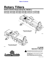
Driveline sprocket removal (continued)
b. Remove sprocket mounting bolts (J) and lockwashers.
c. Remove driveline shaft nuts (K, L) and remove sprocket.
4. Install driveline sprocket:
a. Install new sprocket (M). 18T for Lexion, 20T for Agco, all others 24T.
b. Install sprocket mounting bolts (J).
c. Install driveline shaft nut (K) and torque to 70-75 ft-lbs to seat bearings.
d. Back off driveline nut (K) one turn.
e. Retighten driveline nut (K) to 2-5 ft-lbs.
f. With bar (H) still inserted though driveline u-joint, hold driveline nut (K) and torque
driveline nut (L) to 110/140 ft lbs.
g. Tighten and torque sprocket mounting bolts (J) to 35 ft-lbs.
5. Reinstall roller chain and tighten tensioning bolt (G) until chain has
12mm of flex in either direction or 24mm (1 inch) total.
6. Reinsert retaining clip and spring (F).
7. Remove all traces of old silicone and apply fresh silicone (P) around fill
plug and 40mm down flange.
8. Reinstall rubber gasket, gearbox cover and flange clamp plates and attach
using existing hardware (A, B). Torque hardware (A, B) until rubber gasket
begins to squeeze out.
9. Replace oil level plug (N) and rotate gearbox back to field position by reversing steps from point 1a. Add 2.5
liters of 85W 140 oil and reinstall fill plug (E).
10. Fill plug (E) must stay upright for a minimum of two hours to allow silicone to cure.
11. Refer to Section 9 (Hydraulic Section) of the D60 /FD70 & CA20 DRAPER HEADER SERVICE MANUAL to
check knife drive flow and pressure.
M
K
L
J
DRIVELINE SPROCKET REMOVAL/INSTALL
P
/