Page is loading ...


1.0 General Section
Table of Contents
1.1 Purpose
1.2 Introduction to the Telephone Package (Motorola digital Phone)
1.2.1 CDMA, TDMA and GSM Protocols
1.2.2 CDMA, TDMA and GSM Handset Descri
p
tions
1.2.3 Phone Activation/Pro
g
rammin
g
1.3
Telephone System Components
1.3.1 Phone Cradle
1.3.2 Microphone
1.3.3A Portable Support Electronics Module (PSE)
1.3.3B Communication Platform Module (CP)
1.3.3C Multiple Handset Interface Module (MHI)
1.3.4 Handset
1.3.5 Compensator
1.0 General Section
Mercedes Benz Technical Manual for Telephone v4.6 Date: 09/01/2004

1.1 Purpose
This manual was written to familiarize the Mercedes-Benz Service Technician with the telephone
system designed by Motorola for Mercedes-Benz MY00 thru MY05 vehicles. It is recommended that
this training manual be reviewed prior to performing the installation of the telephone package. This
document is not an installation guide or procedure, a separate Mercedes-Benz manual has been created
for that purpose. However, basic troubleshooting charts are included as a part of this document to assist
in correcting problems that may occur.
1.2 Introduction to the Telephone Package (Motorola Digital Phone)
Prior telephone systems that have been installed in Mercedes-Benz vehicles have used only 800MHz
analog technology. The MY00 uses the 800MHz analog/digital and MY01/05 uses 1900MHz digital in
addition to 800MHz analog/digital. MY00 thru MY04 telephone packages use CDMA or TDMA
protocols and, MY05 vehicles offer the option of GSM as a third protocol depending on the model
selected for installation, which will be determined by the customer and/or carrier availability.
Additionally, the telephone package has the ability to automatically default to an analog signal if a
digital signal is not available, or is too weak to provide a quality conversation.
The telephone package allows calls to be made and received without taking your eyes off the road or
your hands off the steering wheel. This is accomplished by integrating the phone with the
multifunction controls located on the sides of the steering wheel (if equipped) and through Voice
Recognition (if equipped). Displays on the MCS, Audio 30 or COMAND relay information, such as,
numbers stored in the handset’s memory, signal strength, etc. Refer to the K2OPTION owner’s manual
for details on the various features of this system.
1.2.1 CDMA, TDMA and GSM Protocols
CDMA is an acronym for Code Division Multiple Access. It is one of several methods of providing
digital cellular service. CDMA imposes several digital signal patterns, one pattern per conversation,
on a single carrier frequency. The communication link (conversation) is kept separated from other
links by the ability of the telephone to only recognize its assigned signaling pattern (code). CDMA
technology is popular because it provides for a large number of communication links on a single
carrier frequency, but one of its drawbacks is that as more links are established, distortion and
interference increases.
TDMA stands for Time Division Multiple Access, and is another method of providing digital cellular
service with multiple links (conversations) on the same carrier frequency. It differs from CDMA in that it
uses slots of time for each link. Each time slot repeats continuously at a predetermined rate or speed.
Samples of each link are taken at the same rate and mixed with the carrier frequency, each in its turn. On
the receiving end, the receiver selects the data from the time slots of the assigned communication link,
1.0 General Section
Mercedes Benz Technical Manual for Telephone v4.6 Date: 09/01/2004

and then filters the data to provide a good representation of the original information.
GSM stands for Global System for Mobile Communication, and is similar to both CDMA and TDMA
protocols in that it also provides digital cellular service with multiple links (conversations) on the same
carrier frequency. Like both CDMA and TDMA, GSM uses its own unique method of transmitting
conversation wirelessly. GSM is based on the platform of TDMA, but a more robust method when
utilizing the timeslots allotted for the milliseconds of data needing to be transferred/received. GSM is
also unique in that it utilizes a ‘smart card’ called Subscriber Identity Module (SIM) allowing for easy
portability between different GSM handsets. GSM handsets are not identified like both CDMA and
TDMA handsets by using an Electronic Serial Number (ESN); instead it is uniquely identified by the
International Mobile Equipment Identity (IMEI).
The type of digital handset that will be installed into the vehicle will be contingent upon the local
carrier’s signal processing capabilities. Some carriers only use CDMA protocols whereas others may
only use TDMA or GSM. It is possible in some areas for the customer to have a choice of all three
protocols to use when carriers in the same cellular coverage area offer CDMA technology while others
offer TDMA or GSM technologies. Some carriers are requiring special ‘un-lock codes’ for handsets that
are to be used in their coverage area and on their systems. It is important to be aware of this in the event
that you experience trouble with activating the phone. More information regarding these codes is
available through the carrier, which the handset is being activated on. Refer to the Mercedes-
Benz/Motorola website (www.mbconnectedcar.com) or Motorola’s Customer Support at 877-668-8600
for carrier contact numbers.
1.2.2 CDMA, TDMA and GSM Handset Descriptions
The CDMA StarTAC and Timeport handsets have three partially blue keys with an icon that represents a
"soft key" function. Soft keys are keys that change their function according to what is being displayed
on the screen for a particular function. These keys are located on the fifth row of the keypad and are on
the "RCL", "STO", and "CLR" keys.
Another way to differentiate between a TDMA and CDMA handset is to compare the displays. The
CDMA handset uses the OELD (Organic Electro Luminescent Display, Timeport only). The TDMA
handset uses 5-line LCD dot-matrix display. The TDMA Timeport and v.60t handsets have a fixed
antenna compared to the traditional extendable antenna on both of the StarTAC’s and CDMA Timeport
and v.60c. The CDMA phones and TDMA v.60t indicates that the user is in digital mode by displaying a
“D” inside a square border on the left side of the display, vs. a "D" with no border in the lower left hand
corner of the TDMA StarTAC and Timeport handsets. When in analog mode, the StarTAC and
Timeport CDMA handsets display an “A” inside a circle; the StarTAC and Timeport TDMA handsets
are in analog mode when no “D” is present in the lower left corner of the display. When both the CDMA
v.60c and TDMA v.60t are in analog mode an “A” is present inside a square, instead of a “D”. GSM
handsets use a removable ‘smart card’ known as SIM, which is found under the battery. Other detailed
differences can be found in the owner’s manual for the specific handset functions.
In addition to the above criteria, there will be a separate part number for each type of handset.
Reference the Mercedes-Benz/Motorola website for part numbers and availability according to zip
code.
1.0 General Section
Mercedes Benz Technical Manual for Telephone v4.6 Date: 09/01/2004

1.2.3 Phone Activation/Programming
The programming procedure for a CDMA handset is not the same as a TDMA handset. There are also
programming differences between StarTAC/Timeport and v.60 procedures. Refer to following
programming card appropriate for the desired handset being programmed.
NOTE 1: ANY PROGRAMMING OF HANDSETS REQUIRING AN ‘UN-LOCK CODE’ NEED
ADDITIONAL ASSISTANCE FROM THE CARRIER SPECIFIED BY THE HANDSET.
NOTE 2: PROGRAMMING / ACTIVATION FOR HANDSETS RELEASED AFTER THE V60I
SERIES PHONE ARE FULLY SUPPORTED BY THE CARRIER SUPPLYING CELLULAR
SERVICE TO THE PHONE.
CDMA StarTAC/TIMEPORT PROGRAMMING CARD
TO ENTER PHONE DISPLAYS
1
Enter NAM 1
programming mode
PRESS 7, 4, 6, 6, 3, #, 1, FCN, FCN Enter MIN
2
Enter Your
Phone Number
Use the keypad to enter all ten digits of
your phone number and press “STO”
Sample Number:
312-555-1212
3
Enter AMPS System
ID (Analog)
Enter _ _ _ _ _. Press “STO” Sample Number:
11111
4
Enter Digital
System ID
Enter _ _ _ _ _. Press “STO” Sample Number:
11111
TDMA StarTAC/TIMEPORT PROGRAMMING CARD
TO ENTER PHONE DISPLAYS
1
Enter programming
mode
PRESS “#”, Carrier System ID,
“#”, “*”, “SEND”
Nam 1 Prog
*= Yes #= No
2
PRESS “*” Security
Code _ _ _ _ _ _
3
Enter Security Code PRESS 0, 0, 0, 0, 0, 0
(This is the code that is in the phone
when it is shipped out of the factory)
Phone displays its ESN
(Electronic Serial Number)
4
PRESS “SEND” Phone #
_ _ _ _ _ _ _ _ _ _
5
Enter Phone Number ENTER Entire Phone Number
(_ _ _) _ _ _ - _ _ _ _
PRESS “SEND” NAM Program Begins
1.0 General Section
Mercedes Benz Technical Manual for Telephone v4.6 Date: 09/01/2004

CDMAv.60c PROGRAMMING CARD
TO ENTER PHONE DISPLAYS
1
Enter Programming Mode PRESS 7, 4, 6, 6, 3, #, MENU,
MENU
Nam 1
Nam 2
2
Selecting NAM CHOSE “SELECT” for NAM 1 MIN: 0000000000
3
Enter Phone Number INSERT 10-digit MIN through the
keypad and SELECT “OK”
(This is the customers cellular
number)
IMSI
4
Enter AMPS system ID SCROLL down to AMPS Sys ID
and INSERT number then SELECT
“OK”
(AMPS data provided by carrier)
CDMA Sys ID:
5
Enter CDMA system ID INSERT CDMA Sys ID then
SELECT “OK”
(CDMA data provided by carrier)
MIN:
6
Finalizing Programming SELECT “DONE” then PRESS the
“END” key
Main Menu
TDMA v.60t PROGRAMMING CARD
TO ENTER PHONE DISPLAYS
1
Enter Programming Mode PRESS #, Carrier System I.D., #,*,
“SEND”
Enter Security Code
-----------------
2
Enter Security Code PRESS 0,0,0,0,0,0, and SELECT
“OK”
(This is the factory default code)
ESN (Hex)
3
Enter Phone Number SCROLL down to MIN: ---------------
-
and INSERT 10-digit MIN through
the keypad and SELECT “OK”
(MIN is the customer cell number)
IMSI
4
Finalizing Programming SELECT “DONE” (the handset
display will turn off temporarily)
Main Menu
1.0 General Section
Mercedes Benz Technical Manual for Telephone v4.6 Date: 09/01/2004

1.3 Telephone System Components
The Motorola integrated telephone packages from MY2000 thru MY2005 consist of the following
components:
KEY: ‘1’ = PSE/D2B Components, ‘2’ = CP/MOST Components, ‘3’ = MHI/MOST Components
Antenna Switch (Splitter for SL only) – 1, 3
Coil Cord – 1, 2
Compensator – 1, 2, 3
Communication Platform Module - 2
D2B Wiring – 1
MOST Wiring – 2, 3
Motorola Cellular Telephone
(CDMA, TDMA or GSM with Mercedes-Benz Logo and Software) – 1, 2, 3
Multiple Handset Interface Module (MHI) - 3
Phone Cradle – 1, 2, 3
Portable Support Electronics Module (PSE) – 1
Voice Recognition Module (Optional Kit on Some Models) – 1, 2, 3
“Y” Cable – 1
The components of the telephone package between MY2000 and MY2001 are not compatible or
interchangeable due to the technological differences between the two systems. The MY2000 telephone
package is 800MHz only and cannot support the MY2001 telephone package components, which are
1900MHz in addition to the 800MHz.
Figures 1 thru 10 of the StarTAC/Timeport Block Diagram provide illustrations of the telephone
package component layout for the MY2000/01 S-Class (W220, C215), CLK (A208, C208), E-Class
(W210, S210), SL (R129), C-Class (W203), SLK (R170), and M-Class (W163) MY2000 & MY2001
Mercedes-Benz when utilizing the PSE module and D2B system. Figures 1 thru 9 of the v60 Block
Diagram provide illustrations of the telephone package component layout for the aforementioned
Classes reflecting MY2002/04 when utilizing the PSE module and D2B system. Figures 1 thru 6, 9 of
the CP Block Diagram provide illustrations of the telephone package component layout for the
MY2003/04 E-Class (BR211) and MY2004 S-Class (BR220), CL-Class (BR215) and Maybach
(BR240) when utilizing the CP module and MOST system. Figures 1 thru 6, 8, 9 of the MHI Block
Diagram provide illustrations of the telephone package component layout for all the MY2005 vehicle
chassis when supported by the MHI module and MOST system. These drawings and components are
discussed in greater detail beginning with section 3.1.
1.3.1 Phone Cradle
The MY2001 phone cradle is similar in appearance to the MY2000 phone cradle, except that it has been
modified to accommodate the Motorola Timeport
™
handset. The MY2002/04 phone cradles clip into
the cradle base for full integration and is removable allowing for ease of use in private mode. The cradle
1.0 General Section
Mercedes Benz Technical Manual for Telephone v4.6 Date: 09/01/2004


Class (BR220), CL-Class (BR215) and Maybach (BR240). The CP module for the telephone package
contains the PSE box supporting the software and associated electronics for the integration of the handset
to the vehicle. The CP module also contains the Tele-Aid module supporting the emergency notification
system in the vehicle.
1.3.3C Multiple Handset Interface Module (MHI)
MHI was introduced on the MY2005 vehicles across all chassis except for Maybach, which still utilizes
the CP module. The MHI module is similar to the PSE module in that it supports the portable phone’s
initial integration for the telephone package into the vehicle system, but communicates using the MOST
vehicle bus instead of the D2B vehicle bus. The MHI system is designed to be forwards-compatible with
future portable phones (the user only needs to change the cradle in order to upgrade to new portables in
the future). The MHI also has integrated software to perform the Hands-free Audio function, such that the
Microphone Array Module from AKG is no longer required to be part of the system.
1.3.4 Handset
A Motorola Digital handset is used for the telephone system. Although the Digital handset is available as
a portable phone sold separately by various vendors, it will not interface with the Mercedes-Benz vehicle.
Only handsets that are part of the telephone package will interface with the Mercedes-Benz vehicle. They
can also be used as a portable cellular phone when not interfacing with the vehicle. The three types of
handsets available for the telephone package are digital TDMA, CDMA or GSM, which will be
determined by the customer and/or carrier availability. Refer to section 1.2.1 and 1.2.2 of this manual and
the appropriate user manual for a full description of each handset and a detailed explanation of CDMA,
TDMA and GSM technologies. The customer will have the option to purchase more than one handset
that can also be integrated with the same vehicle, but only one handset can be integrated at any time.
1.3.5 Compensator
The compensator is used to "compensate" for the small amount of power that is lost as a result of the
extra RF cable needed to send or receive the signal through the vehicles antenna. The compensator is not
a booster when in digital or analog modes. Refer to section 4 for a complete layout and description of the
RF path, which includes the compensator.
~ The voice activation feature interfaces with the telephone package. It is treated as a separate system and
is not covered in this manual.
Mercedes Benz Technical Manual for Telephone v4.6 Date: 09/01/2004
1.0 General Section

2.0 Wiring Section
2.0 Electrical Connectors and Wiring Section
Table of Contents
2.1 __ StarTAC/Timeport Layout, Connectors and Schematics
2.2 V.60 Layout, Connectors and Schematics
2.3 CP Layout and Schematics
2.4 MHI Layout and Schematics
Mercedes Benz Telephone Manual v4.6 Date: 09/01/2004

2.0 Wiring Section
Mercedes Benz Telephone Manual v4.6 Date: 09/01/2004
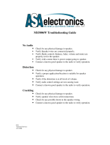
2.1 StarTAC/Timeport Connectors and Schematic Key
2.1.1 StarTAC/Timeport Block Diagram (All classes except M class)
2.1.2 StarTAC/Timeport M-class Block Diagram
2.1.3 StarTAC/Timeport Y Cable Connector Pin-out (all classes except M class)
2.1.4 StarTAC/Timeport Wiring Diagram (all classes except M class)
2.1.5 StarTAC/Timeport M-class Y Cable Connector Pin-out
2.1.6 StarTAC/Timeport M-class Wiring Diagram
2.1.7 StarTAC/Timeport Coil Cord Pin-out


2.0 Wiring Section
Mercedes Benz Telephone Manual v4.6 Date: 09/01/2004
2.1.1 StarTAC/Timeport Block Diagram (All Classes Except M Class)

2.0 Wiring Section
Mercedes Benz Telephone Manual v4.6 Date: 09/01/2004
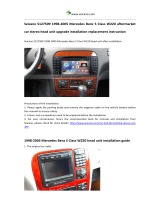
2.1.2 StarTAC/Timeport M-Class Block Diagram


2.0 Wiring Section
Mercedes Benz Telephone Manual v4.6 Date: 09/01/2004
Table of Contents
2.2 ___ v.60 Connectors and Schematic Key
2.2.1 v.60 Block Diagram (All classes except M class)
2.2.2 v.60 M-class Block Diagram
2.2.3 v.60 Y Cable Connector Pin-out (all classes except M class)
2.2.4 v.60 Wiring Diagram (all classes except M class)
2.2.5 v.60 M-class Y Cable Connector Pin-out
2.2.6 v.60 M-class Wiring Diagram
2.2.7 v.60 Coil Cord Pin-out
/