Page is loading ...

StarTAC 160 (GSM)
Cellular Subscriber Sector
The World’s Leading Cellular
Telephone Manufacturer
Service Manual
Issue 1.0

© 1998 Motorola, Inc. Issue 1.0 iii
PREFACE
StarTAC 160 (GSM)
Cellular Subscriber Sector
Preface
Specifications
Table 1: General
Function Specification
Frequency Range 890-915 MHz TX
935-960 MHz RX
Channel Spacing 200 kHz
Channels 124 carriers with 8 channels per carrier
Modulation GMSK at BT = 0.3
Transmitter Phase Accuracy 5 Degrees RMS, 20 Degrees peak
Duplex Spacing 45 MHz
Frequency Stability +
0.10 ppm of the downlink frequency (Rx)
Operating Voltage +3.0V dc to +5.1V dc (battery)
+4.4V dc to +6.5V dc (external connector)
Transmit Current <200 mA average, 1.0 A peak
Stand-by Current Average 10mA (DRX 2)
Dimensions 98.3 mm (L) x 57.3 mm(W) x 22.5 mm(D)
Size (Volume) 100 cubic cm
Weight Approximately 99.5 g; Includes Slim LiIon battery pack and
antenna
Temperature Range -20
°
C to +55
°
C
Table 2: Transmitter
Function Specification
RF Power Output 33 dBm +
2dBm

iv Issue 1.0 2/6/98
StarTAC 160 (GSM)
Specifications subject to change without notice
.
Output Impedance 50 ohms (nominal)
Spurious Emissions -36 dBm up to 1 GHz, (<-30 dBm > 1 GHz)
Table 3: Receiver
Function Specification
RF Level -102 dBm
RX bit error rate (100 k bits) < 2%
Channel Hop Time 500 microseconds
Time to Camp Approximately 10 seconds
Table 4: Speech Coding
Function Specification
Speech Coding Type Regular Pulse Excitation / Linear Predictive Coding with
Long Term Prediction. (RPE LPC with LTP).
Bit Rate 13.0 k bps
Frame Duration 20 ms
Block Length 260 bits
Classes Class 1 bits = 182 bits. Class 2 bits = 78 bits
Bit Rate with FEC Encoding 22.8 k bps
Table 2: Transmitter
Function Specification

2/6/98 Issue 1.0 v
Preface
Foreword
Scope of Manual
This manual is intended for use by experi-
enced technicians familiar with similar
types of equipment. It is intended primarily
to support electrical and mechanical repairs.
Repairs not covered in the scope of this
manual should be forwarded to Motorola’s
regional Cellular Subscriber Support
Centers.
Authorized distributors may opt to receive
additional training to become authorized to
perform limited component repairs. Contact
your regional Customer Support Manager
for details.
Model and Kit Identification
Motorola products are specifically identified
by an overall model number on the FCC
label. In most cases, assemblies and kits
which make up the equipment also have kit
model numbers stamped on them.
Motorola maintains a parts office staffed to process parts orders, identify part
numbers, and otherwise assist in the maintenance and repair of Motorola Cellular
products. Orders for all parts should be sent to the Motorola International Logis-
tics Department at the following address:
Attn: Global Spare Parts Department
Motorola Cellular Subscriber Group
2001 N, Division St.
Harvard, IL 60033-3674
U. S. A.
FAX: 1-815-884-8354
When ordering replacement parts or equipment information, the complete identi-
fication number should be included. This applies to all components, kits, and
chassis. If the component part number is not known, the order should include the
number of the chassis or kit of which it is a part, and sufficient description of the
desired component to identify it.
Replacement Parts Ordering
Service
Motorola’s regional Cellular Subscriber
Support Centers offer some of the finest
repair capabilities available to Motorola
Subscriber equipment users. The Cellular
Subscriber Support Centers are able to
perform computerized adjustments and
repair most defective transceivers and
boards. Contact your regional Customer
Support Manager for more information
about Motorola’s repair capabilities and
policy for in-warranty and out-of-warranty
repairs in your region.

vi Issue 1.0 2/6/98
StarTAC 160 (GSM)
General Safety Information
Portable Operation
DO NOT
hold the radio so that the antenna
is very close to, or touching, exposed parts
of the body, especially the face or eyes, while
transmitting. The radio will perform best if
it is held in the same manner as you would
hold a telephone handset, with the antenna
angled up and over your shoulder. Speak
directly into the mouthpiece.
DO NOT
operate the telephone in an
airplane.
DO NOT
allow children to play with any
radio equipment containing a transmitter.
Mobile Operation (Vehicle Adaptor)
As with other mobile radio transmitting
equipment, users are advised that for satis-
factory operation of the equipment and for
the safety of personnel, it is recommended
that no part of the human body shall be
allowed to come within 20 centimeters of the
antenna during operation of the equipment.
DO NOT
jump start vehicle or use an auto-
motive battery charger while the vehicle
adapter option and the portable radiotele-
phone are connected to the vehicle electrical
system as this may cause serious damage to
the radio. Disconnect the radio by removing
the cable kit fuses.
DO NOT
operate this equipment near elec-
trical blasting caps or in an explosive atmo-
sphere. Mobile telephones are under certain
conditions capable of interfering with
blasting operations. When in the vicinity of
construction work, look for and observe
signs cautioning against mobile radio trans-
mission. If transmission is prohibited,
the
cellular telephone
must be turned off
to
prevent any transmission.
In standby mode,
the mobile telephone will automatically transmit
to acknowledge a call if it is not turned off.
All equipment must be properly grounded
according to installation instructions for safe
operation.
Portable/Mobile Telephone Use
and Driving
Safety is every driver’s business. The
portable telephone should only be used in
situations in which the driver considers it
safe to do so. Use of a cellular portable while
driving may be
illegal
in some areas.
Refer to the appropriate section of the
product service manual for additional perti-
nent safety information.

© 1998 Motorola, Inc. Issue 1.0 vii
CONTENTS
StarTAC 160 (GSM)
Cellular Subscriber Sector
Preface . . . . . . . . . . . . . . . . . . . . . . . . . . . . .iii
Specifications . . . . . . . . . . . . . . . . . . . . . . . . . .iii
Foreword . . . . . . . . . . . . . . . . . . . . . . . . . . . . . . v
Replacement Parts Ordering . . . . . . . . . . . . . . .v
General Safety Information . . . . . . . . . . . . . . . vi
Description . . . . . . . . . . . . . . . . . . . . . . . . . 1
Product Description . . . . . . . . . . . . . . . . . . . . . .1
Theory of Operation . . . . . . . . . . . . . . . . . . 3
GSM System Overview . . . . . . . . . . . . . . . . . . .3
General Cellular Concept . . . . . . . . . . . . . . . . .3
GSM Description . . . . . . . . . . . . . . . . . . . . . . . .3
Identity and Security . . . . . . . . . . . . . . . . . 7
Transceiver Labelling . . . . . . . . . . . . . . . . . . . .7
Mini SIM CARDS . . . . . . . . . . . . . . . . . . . . . . . .8
Testing . . . . . . . . . . . . . . . . . . . . . . . . . . . . 11
Verification . . . . . . . . . . . . . . . . . . . . . . . . . . . .11
Manual Test Mode . . . . . . . . . . . . . . . . . . . . . .12
Personality Transfer . . . . . . . . . . . . . . . . . 15
Introduction . . . . . . . . . . . . . . . . . . . . . . . . . . .15
Normal Transfer . . . . . . . . . . . . . . . . . . . . . . .15
Master Transfer . . . . . . . . . . . . . . . . . . . . . . . .16
Master SIM Card Creation . . . . . . . . . . . . . . . .17
Disassembly . . . . . . . . . . . . . . . . . . . . . . . .19
Introduction . . . . . . . . . . . . . . . . . . . . . . . . . . . 19
Recommended Tools . . . . . . . . . . . . . . . . . . . 19
Transceiver Disassembly . . . . . . . . . . . . . . . . 19
Troubleshooting . . . . . . . . . . . . . . . . . . . .27
Introduction . . . . . . . . . . . . . . . . . . . . . . . . . . . 27
Troubleshooting And Repair . . . . . . . . . . . . . . 27
Testing After Repair . . . . . . . . . . . . . . . . . . . . 27
Troubleshooting Supplements . . . . . . . . . . . . 33
Electrical Diagrams . . . . . . . . . . . . . . . . . . . . . 43
Replacement Parts . . . . . . . . . . . . . . . . . .45
Mechanical . . . . . . . . . . . . . . . . . . . . . . . . . . . 45
Service Tools for StarTAC . . . . . . . . . . . . . . . 59
Glossary . . . . . . . . . . . . . . . . . . . . . . . . . . .61
Service Manual Feedback Form . . . . . . . .67

viii Issue 1.0 2/6/98
StarTAC 160 (GSM)

© 1998 Motorola, Inc. Issue 1.0 1
DESCRIPTION
StarTAC 160 (GSM)
Cellular Subscriber Sector
Description
Product Description
General
This personal
cellular telephone is a micro-
processor controlled, full duplex, synthe-
sized FM radiotelephone using digital
modulation techniques, for use in compat-
ible 900 MHz cellular radiotelephone
systems. When operated properly, the
equipment will provide the user with land-
linked telephone service through individual
cell site base stations, all linked to a central
control office. The phone has a 3.0 Watt
maximum power capability.
Physical Packaging
The transceiver circuitry is contained in a
water resistant polycarbonate plastic
housing that is less than 100 cc at a weight of
less than 100 grams with the lightest battery.
The transceiver circuitry is contained on two
multi-layer boards, the RF/Logic board, and
the keyboard assembly.
The RF/Logic board houses the RF and
Audio/Logic circuitry on separate sides in
addition to SIM contacts, the alert, a 16 posi-
tion ZIF connector, the microphone, and an
external connector.
The keyboard assembly houses the display,
reed switch, and keyboard LEDs. Electrical
connections between the two boards are
provided by connectors at the lower portion
of each board.
The silent alert and speaker are located
inside the top portion of the housing and is
connected to the RF/Logic board via a flex
strip that connects to the 16 position ZIF.
Operating power for the personal telephone
can be obtained from any one of the main or
auxiliary batteries, or an external supply
such as a cigarette lighter adapter (CLA).
NOTE
The phone may have various battery
options as standard depending on the
particular market requirements.

2 Issue 1.0 2/6/98
StarTAC 160 (GSM)

© 1998 Motorola, Inc. Issue 1.0 3
THEORY OF OPERATION
StarTAC 160 (GSM)
Cellular Subscriber Sector
Theory of Operation
GSM System Overview
General Cellular Concept
The cellular systems are used to provide
radiotelephone service in the frequency
range 890-960 MHz. A cellular system
provides higher call handling capacity and
system availability than would be possible
with conventional radiotelephone systems
(those which require total system area
coverage on every operating channel) by
dividing the system coverage area into
several adjoining sub-areas or cells.
Each cell contains a base station (cell site)
which provides transmitting and receiving
facilities, for an allocated set of duplex
frequency pairs (channels). Since each cell is
a relatively small area, both the cell site and
the radiotelephone that it supports can
operate at lower power levels than would be
used in conventional systems.
NOTE
The following description is intended only
as a preliminary general introduction to
the Global System for Mobile communi-
cations (GSM) cellular network. This
description is greatly simplified and does
not illustrate the full operating capabili-
ties, techniques, or technology incorpo-
rated in the system.
Using this technique, radiation on a given
channel is virtually contained in the cell
operating on that channel and, to some
extent, those cells directly adjacent to that
cell.
Since the coverage area of a cell on a given
channel is limited to a small area (relative to
the total system coverage area), a channel
may be reused in another cell outside the
coverage area of the first. By this means,
several subscribers may operate within the
same geographic area, without interference
with each other, on a single channel.
GSM Description
Unlike previous cellular systems, GSM uses
digital radio techniques. The GSM system
has the following advantages over previous
analogue systems:-
•
International Roaming
-
Due to
international harmonization and
standardization, it will be possible to make
and receive calls in any country which
supports a GSM system.
•
Digital Air Interface
-
The GSM phone
will provide an entirely digital link
between the telephone and the base
station, which is, in turn, digitally linked
into the switching subsystems and on into
the PSTN.
•
ISDN Compatibility
-
ISDN is a digital
communications standard that many
countries are committed to implementing.

4 Issue 1.0 2/6/98
StarTAC 160 (GSM)
It is designed to carry digital voice and
data over existing copper telephone
cables. The GSM phone will be able to
offer similar features to the ISDN
telephone.
•
Security and Confidentiality
-
Telephone
calls on analogue systems can very easily
be overheard by the use of a suitable radio
receiver. GSM offers vastly improved
confidentiality because of the way in
which data is digitally encrypted and
transmitted.
•
Better Call Quality
-
Co-channel
interference, handover breaks, and fading
will be dealt with more effectively in the
digital system. The call quality is also
enhanced by error correction, which
reconstructs lost information.
•
Efficiency
-
The GSM system will be able to
use spectral resources in a much more
efficient way than previous analogue
systems.
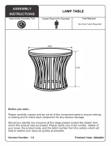
In the figure below, the area bounded by
bold lines represents the total coverage area
of a hypothetical system. This area is
divided into several cells, each containing a
cell site (base station) operating on a given
set of channels which interfaces radiotele-
phone subscribers to the telephone
switching system.
Figure 1: Hypothetical Cell System
The
radiotelephones themselves are capable
of operation on any channel in the system,
allowing them to operate in any cell. Due to
the low power requirements for communi-
cations between radiotelephones in a partic-
ular cell and the cell site, operating channels
may be repeated in cells which are outside
the coverage area of each other.
For example, presume that cell A operates
on channels arbitrarily numbered 1 through
8, cell B operates on channels 9 through 16,
cell C operates on channels 17 through 24
and cell D operates on channels 1 through 8
(repeating the usage of those channels used
by cell A). In this system, subscribers in cell
A and subscribers in cell D could simulta-
neously operate on channels 1 through 8.
The implementation of frequency re-use
increases the call handling capability of the
system, without increasing the number of
available channels. When re-using identical
frequencies in a small area, co-channel inter-
ference can be a problem. The GSM system
can tolerate higher levels of co-channel
interference than analogue systems, by
incorporating digital modulation, forward
error correction and equalization. This
means that cells using identical frequencies
can be physically closer, than similar cells in
analogue systems. Therefore the advantage
of frequency re-use can be further enhanced
in a GSM system, allowing greater traffic
handling in high use areas.
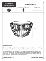
By incorporating Time Division Multiple
Access (TDMA) several calls can share the
same carrier. The carrier is divided into a
continuous stream of TDMA frames, each
frame is split into eight time slots. When a
connection is required the system allocates
the subscriber a dedicated time slot within
each TDMA frame. User data (speech/data)
for transmission is digitized and sectioned
into blocks. The user data blocks are sent as
information bursts in the allocated time slot
of each TDMA frame, see Figure 2: “TDMA
Transmission” on page 5.
•
•
•
•
•
•
•
•
•
•
•
•
CHANNELS
1-8
CHANNELS
CHANNELS
CHANNELS
9-16
1-8
9-16
CELL A
CELL B
CELL D
CELL E
•
CHANNELS
17-24
CELL C
•
CHANNELS
17-24
CELL F

2/6/98 Issue 1.0 5
Theory of Operation
The data blocks are modulated onto the
carrier using Gaussian Minimum Shift
Keying (GMSK), a very efficient method of
phase modulation.
Figure 2: TDMA Transmission
Each time an information burst is trans-
mitted, it may be transmitted on a different
frequency. This process is known as
frequency hopping. Frequency hopping
reduces the effects of fading, and enhances
the security and confidentiality of the link. A
GSM radiotelephone is only required to
transmit for one burst in each frame, and not
continually, thus enabling the unit to be
more power efficient.
Each radiotelephone must be able to move
from one cell to another, with minimal
inconvenience to the user. The mobile itself
carries out signal strength measurements on
adjacent cells, and the quality of the traffic
channel is measured by both the mobile and
the base station. The handover criteria can
thus be much more accurately determined,
and the handover made before the channel
quality deteriorates to the point that the
subscriber notices.
When a radiotelephone is well within a cell,
the signal strength measured will be high.
As the radiotelephone moves towards the
edge of the cell, the signal strength and
quality measurement decreases.
Signal information provides an indication of
the subscriber’s distance from the base
station. As the radiotelephone moves from
cell to cell, its control is handed from one
base station to another in the new cell.
This change is handled by the radiotele-
phone and base stations, and is completely
transparent to the user.
Service Area
The area within which calls can be placed
and received is defined by the system opera-
tors. (Because this is a radio system, there is
no exact boundary that can be drawn on a
map.) If the telephone is outside a coverage
area, the (no service) indicator will illumi-
nate and calls will be unable to be placed or
received. If this happens during a conversa-
tion, the call will be lost. There may also be
small areas within a particular service area
where communications may be lost.
The radiotelephone’s identity information
is held by its local GSM system in its Home
Location Register (HLR) and Visitor Loca-
tion Register (VLR). The VLR contains iden-
tity information on all local active
radiotelephones. Should you roam to
another area, system or country the radio-
telephones identity information is sent to
the VLR in the new system. The new system
will then check the radiotelephones details
with your home system for authenticity. If
everything is in order it will be possible to
initiate and receive calls whilst in the new
area.
01234
5
6701234
5
6701234
5
6701234
5
67
Frame 0 Frame 3Frame 2Frame 1
User Data Sectioned Into Blocks
Information Bursts Sent In Allocated Time Slots

6 Issue 1.0 2/6/98
StarTAC 160 (GSM)

© 1998 Motorola, Inc. Issue 1.0 7
IDENTITY AND SECURITY
StarTAC 160 (GSM)
Cellular Subscriber Sector
Identity and Security
Transceiver Labelling
Introduction
Each Motorola GSM transceiver will be
labelled with various number configura-
tions. The following information shows and
explains the common labelling titles.
Title Explanations
MSN
The Mechanical Serial Number (MSN) is an
individual number, uniquely identifying the
unit. The MSN will remain the same
throughout the units life, even if the main
board is replaced. Because the MSN is
unique to the unit, it is often used for
logging and tracking purposes by Motorola
National Service Centres on EPPRS. The
MSN is divided into the sections shown
below.
Figure 3: MSN Configuration
CEPT GSM
This is the International Mobile Station
Equipment Identity (IMEI) number. The
IMEI is held in the logic circuitry.
If the main board is replaced then the units
IMEI will change, therefore the units label-
ling should be updated with the new IMEI.
An IMEI uniquely identifies a mobile station
equipment to the system, and is divided into
the sections shown below.
Figure 4: IMEI Configuration
REV S/H
This configuration consists of two blocks of
two digits, and denotes the software and
hardware versions within the unit. The first
two digits correspond to the software
version, and the last two digits correspond
to the hardware version. If a version update
is carried out on the unit, the corresponding
change information should be made
apparent on the labelling.
Model
The model number defines the type of
product. Each product type is issued a
common model number.
Package
The package number is used to determine
the type of equipment, the mode in which it
was sold, and the language with which it
was shipped.
3 digits 1 digit 2 digits 4 digits
Model
Code
Origin
Code
Date
Code
Serial
Number
MSN 10 digits
MC
OC
DC SNR
6 digits 2 digits 6 digits 1 digit
TAC FAC
SNR
SP
Type
Approval
Code
Final
Assembly
Code
Serial
Number
Spare
IMEI 15 digits

8 Issue 1.0 2/6/98
StarTAC 160 (GSM)
Mini SIM CARDS
Introduction
The Motorola GSM StarTAC 160 is designed
to work with the mini size Subscriber Iden-
tity Module (SIM). The Mini SIM card slides
into the phone sideways. The Mini SIM card
contains all the personal data required to
access GSM services. Data held by the Mini
SIM card includes:
• International Mobile Subscriber Identity
• Temporary Mobile Subscriber Identity
• Home system
• Services subscribed to
• PIN and unblocking codes
• Call barring codes
The Mini SIM card may also be capable of
storing phone numbers and names.
Mini SIM Card Insertion/Removal
The Mini SIM card must be inserted into the
unit correctly so that the card can be read,
and the data checked for validity, before
operation on the system will be enabled. The
card contains all of the user’s personal iden-
tification numbers and details of the system
the phone operates on.
Figure 5: Inserting Mini SIM Card
The Mini SIM card is placed in the tray and
the tray slid into the side of the phone.
Ensure that the Mini SIM card sits correctly
in the tray before trying to insert the tray
into the phone. The tray should be
competely and securely seated in the slot on
the side of the phone.
To remove the Mini SIM tray from the unit,
pull the sliding Mini SIM tray sideways
away fron the phone. The User Guide
contains full information about inserting
and removing the Mini SIM card.
Security Information
To stop unauthorized personnel using your
Mini SIM card, the option of using a
Personal Identity Number (PIN) is available.
When enabled the option requires (on
power up) a verification number to be
entered via the unit’s keypad, before the
card can be used. Three attempts to enter the
correct PIN may be made. If after the three
entries the correct PIN has not been entered,
the card becomes blocked. To unblock the
card an unblocking/super PIN code must be
entered. Ten attempts to enter the correct
unblocking code are permitted, if after ten
attempts the correct code has not been
entered, the Mini SIM card is corrupted and
becomes useless.
Another option available for the Mini SIM
card is call barring. If subscribed to, the call
barring of incoming and/or outgoing calls
may be accomplished by entering a special
key sequence. The key sequence includes a
“barring code”, which determines the type
of restriction incorporated, and a password
to validate the request. The initial password
is provided when you subscribe to the
service. The password can be changed by
entering a set key sequence.
A valid standard sized Mini SIM card can be
used in any working GSM transceiver,
regardless of the manufacturer, which is
compatible with the standard size Mini SIM
card.
Card Slot
Mini SIM Tray
Back of Mini SIM
(Interface contacts on
Mini SIM facing away
from tray.)

2/6/98 Issue 1.0 9
Identity and Security
To protect the actual unit from unauthorized
use, a lock function on the hardware is avail-
able. When enabled, this function requires
that a three or four digit unlock code be
entered, via the units keypad, before normal
operation of the transceiver can take place.
The lock code can be changed by entering a
set key sequence.
Further information on set key sequences
can be derived from the unit’s User Guide.

10 Issue 1.0 2/6/98
StarTAC 160 (GSM)

© 1998 Motorola, Inc. Issue 1.0 11
TESTING
StarTAC 160 (GSM)
Cellular Subscriber Sector
Testing
Testing
Verification
Introduction
To test the StarTAC cellular telephone for
functional verification, the following equip-
ment will be required:
• GSM compatible communications
analyzer.
• Antenna test adaptor (Part No
5880348B33), and appropriate cable/
connectors.
• Test Mini SIM card.
• Charged battery pack.
Equipment Configuration
Initially insert the test Mini SIM card into
the slot at the side of the personal cellular
telephone. If required, further information
on Mini SIM card insertion is available on
page 8. The telephone’s antenna should now
be removed, see “Disassembly” on page 19
for further details. When the antenna has
been removed, attach the antenna adaptor to
the unit. Slide a charged battery on to the
back of the personal telephone, so that the
telephone can be powered up. Finally,
connect a cable from the antenna connector
to the RF in/out port of the communications
analyzer, and power both the analyzer and
personal telephone on. The equipment set
up shown in Figure 6: “Testing Configura-
tion” should now be in place.

12 Issue 1.0 2/6/98
StarTAC 160 (GSM)
Figure 6: Testing Configuration
Test Adaptor
(SKN4683A or
SKN4665A)
Plugs into accessory
connector of phone.
Unit To
Be Tested
GSM Compatible
Communications Analyzer
RF In/out
Port

2/6/98 Issue 1.0 13
Testing
Testing
Accessing The Manual Test Mode
When the Test Mini SIM card is in place,
power up the telephone. Once the initial
automatic ‘wake up’ sequence has taken
place correctly, depress the # key (on the
units keypad) for three seconds. After three
seconds ‘TEST’ should appear in the display,
indicating that the unit is now in the Manual
Test Mode. Table 1: “GSM Test Commands”
on page 13 shows the available Manual Test
commands and their corresponding
results.If a customer should forget the secu-
rity code in their unit, it can only be read or
changed by using a Test Mini SIM card.
Table 1: GSM Test Commands
Key Sequence Test Function/Name
#(hold down for 2 seconds) Enter manual test mode
01# Exit manual test mode
02xxyyy# Display/modify TX power level DAC & load PA calibration table
03x# DAI
05x# Initiate Exec Error Handler Test
07x# Mute RX audio path
08# Unmute RX audio path
09# Mute TX audio path
10# Unmute TX audio path
11xxx# Program main LO to channel
12xx# Set TX power level to fixed value
13x# Display memory block usage
14x# Initiate Out of Memory condition
15x# Generate tone
16# Mute tone generator
19# Display S/W version number of Call Processor
20# Display S/W version number of Modem
22# Display S/W version number of Speech Coder
24x# Set step AGC
25xxx# Set continuous AGC
26xxxx# Set continuous AFC
31x# Initiate Pseudo-Random Sequence- with Midamble
32# Initiate RACH Burst Sequence
33xxx# Synchronize to BCH carrier
34xxxyy# Configuration to TCH/FS & Enable TCH loopback w/o Frame Ensure
Indication
36# Initiate acoustic loopback
37# Stop test
38# Activate Mini SIM
/