YARWAY F884 FLOAT AND THERMOSTATIC STEAM TRAPS
InstallatIon and maIntenance InstructIons
Before installation, these instructions must be carefully read and understood.
GENERAL
These instructions must be carefully read
before any work involving Yarway products is
undertaken.
The installation procedure is a critical stage in
the life of a steam trap and care should be taken
to avoid damage to the trap or equipment.
They give their optimal performance only
when the equipment associated with them is
correctly sized and installed in accordance with
our recommendations.
NOTE
Current regional safety regulations should be taken
into account and followed, while doing the installation
and maintenance work.
Handling, installation and maintenance work must be
carried out by trained personnel. A supervisor must
follow and check all activities.
For the problems that cannot be solved with the help
of these instructions, please contact the supplier or
the manufacturer.
The manufacturer reserves the right to change the
design and material of this product without notice.
CE Marking
This product has been designed for use on
steam and water which are in Group 2 of
the PED-European Pressure Equipment
Directive 97/23/EC and it complies with those
requirements. The product falls within category
SEP and must not be CE marked.
BODY LIMITING CONDITIONS
Flanged PN 16*
Allowable Pressure
Flanged ANSI 150**
Allowable Pressure
Related Temperature
psi bar psi bar °F °C
232 16 232 16 212 100
210 14.5 215 14.8 302 150
194 13.4 197 13.6 392 200
184 12.7 174 12 482 250
Maximum Operating Pressure (PMO): 203 psi (14 bar)
Maximum Operating Temperature (TMO): 388°F (198°C)
* According to EN1092-1:2007
** According to EN1759-1:2004
Body limiting conditions PN 16 or below, depending on the type of connection adopted. Rating PN 16 for
thread.
Model Maximum Differential Pressure
F884-65 65 psi (4.5 bar)
F884-145 145 psi (10 bar)
F884-203 203 psi (14 bar)
ATTENTION
If malfunction of any other equipment or system
operation failure may result in a dangerous
overpressure, over temperature or even vacuum
condition, a safety device must be included in the
system to prevent such situations.
At startup, the presence of small particles in the
fluid (dirt, scale, weld splatters, etc.) may cause
an imperfect closure of the seat. If this occurs,
clean the equipment accordingly.
Do not touch the equipment without appropriate
protection during operation because it may
conduct heat if the used fluid is at high
temperature.
Before starting maintenance be sure that the
equipment is not pressurized or hot. Even if
upstream and downstream isolation valves have
been closed, care should be taken since fluid
under pressure may be trapped between them.
The equipment must be used within their
pressure and temperature limits, otherwise they
may fail (refer to nameplate or documentation).
Manual handling of products may present a risk of
injury. You are advised to assess the risks taking
into account the task, the individual, the load and
the working environment.
Before starting work ensure that you have
suitable tools and/or consumables available. Use
only genuine replacement parts.
Do not remove the nameplate attached to the
equipment. Serial number and other useful
information is stamped on it.
During the assembly work, apply protective
measures against dirt.
When connecting flanges, the bolts should be
mounted from the counter flange side with the
hexagon nuts from the trap side and there must be
a perfect match between the connection flanges.
Tighten flange connection bolts uniformly in a
diagonal sequence.
Correct installation of the equipment is full
responsibility of the user.
Steam traps are designed to be applied in places
protected from exposure to weather.
We recommend special constructions or
protective measures for applications outside or in
adverse environments like corrosion‑promoting
conditions (sea water, chemical vapors, etc.).
Emerson.com/FinalControl © 2019 Emerson. All rights reserved. VCIOM-10113-EN 19/02

2
TRANSPORT AND STORAGE
ATTENTION
Handling and lifting of materials should be done
with appropriate equipment.
The steam traps and equipment should be
protected from impact and forces during
transportation and storage.
The manufacturer doesn’t assume the
responsibility of damaged equipment due to
inappropriate handling during transportation and
storage.
Installation Area Requirements
The installation area should have easy access
and provide enough space for maintenance and
removal operations.
In order to allow installation and maintenance
work without emptying the system, stop valves
should be installed upstream and downstream
of the steam trap.
INSTALLATION
ATTENTION
Account for over pressure conditions, according to
the local laws or standards.
Steam traps must not be used for any
purpose other than the one they were built for
(e.g.climbing aids or as connecting points for
lifting gear).
For the problems that cannot be solved with the
help of these instructions, please contact the
supplier or the manufacturer.
Procedure
1. Prior to installation, check that the product
is suitable for the intended application
(materials and pressure/temperature
ratings).
2. Before installing, remove plastic covers
placed on flanges or connection ends. The
equipment has an arrow or Inlet/Outlet
designations. Be sure that it is installed in
the appropriate direction.
3. Take care with jointing material to ensure
that none may be permitted to block or
enter the trap.
4. If Teflon tape is used (for screwed
connections), avoid rolling it till the edge,
because it can get cut and migrate to
the trap interior, blocking or causing a
defective seal.
5. Install the steam trap at the point of the
system where the condensate tends to
collect.
6. A pipeline strainer should be installed
upstream of the trap to protect from dirt
which could damage the steam trap or
cause malfunctioning. The strainer must
be installed with the sieve sideways, if the
medium is steam, to prevent the collection
of condensate.
STARTUP
ATTENTION
Current regional safety regulations should be
taken into account and followed.
Protective insulation and warning notice may
be required.
Before startup of an existing or a new plant, the
following must be checked:
• All works are completed.
• The steam trap is correctly installed.
• All the necessary safety devices have been
installed.
At startup, the presence of small particles in the
fluid (dirt, scale, weld splatters, joint particles,
remains of Teflon tape, etc.) may cause an
imperfect closure of the seat. If this occurs, clean
the equipment accordingly.
Periodic Checking
24 hours after startup, it is recommended to
check pipe connections for leaks and retighten
the connections if necessary.
YARWAY F884 FLOAT AND THERMOSTATIC STEAM TRAPS
InstallatIon and maIntenance InstructIons
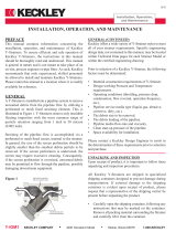
CORRECT INSTALLATION WRONG INSTALLATION
The installation area should have the systems
required to prevent damage of the equipment
due to over temperature/pressure caused
by fire.
If the system cannot be stopped for
maintenance it is recommended that
isolation valves are installed upstream and
downstream of the steam trap together with a
bypass manual regulating valve. The process
can then be controlled manually during the
steam trap maintenance. The bypass must be
kept closed during normal operation.
7. External stresses that may be induced by
the system due to pipe expansion, etc.,
can affect this product. The necessary
precautions are recommended during the
system design and equipment assembly.
8. The steam trap pipework should be
properly supported and free from strain
and it should not be subjected to undue
surges of pressure. The startup condition
should be considered.

3
TROUBLESHOOTING
ATTENTION
If the issues cannot be resolved with the help
of the following chart, please consult the
manufacturer.
Some of these issues may only occur with
certain models.
TROUBLESHOOTING CHART
Issue Possible Reason Solution
Continuous steam discharge.
Damaged seat.
Incorrect installation.
Substitute seat.
Check the installation position
Inadequate condensate
discharge.
Obstructed strainer.
Inadequate pressure
differential.
Excessive back pressure.
Damaged float.
Clean accordingly and
identify the possible reason
for contamination.
Check the steam trap
differential pressure
and substitute.
A larger steam trap end
connection may be required.
Replace.
Temporary condensate
accumulation.
Steam blocking.
Downsizing.
Use a steam trap with SLR.
Check maximum flow rate
(during startup).
Slow intial startup.
Damaged air eliminator.
The air flow is too high for the
trap.
Downsizing.
Replace.
Install an additional air
eliminator.
Check maximum flow rate
(during startup).
YARWAY F884 FLOAT AND THERMOSTATIC STEAM TRAPS
InstallatIon and maIntenance InstructIons
MAINTENANCE
We recommend that the steam traps are
serviced as necessary. Steam traps should be
checked periodically (at least yearly), to verify
that they are operating correctly and to clean
the internal parts and strainer screen (if any).
When reassembling, make sure that all gasket
faces are clean and always use a new gasket.
Tighten cover bolts uniformly in a diagonal
sequence.
Maintenance should proceed as follows:
1. Isolation valves should be closed and
the pressure and temperature must be
atmospheric.
2. Disconnect the steam trap from the line.
3. Execute the maintenance work.
4. Replace and tighten the connections.
(Don’t forget to substitute the gasket).
5. Consider the startup conditions.

4
YARWAY F884 FLOAT AND THERMOSTATIC STEAM TRAPS
InstallatIon and maIntenance InstructIons
PARTS LIST
Key Number Designation Material
1 Body CF8M / 1.4408
2 Cover CF8M / 1.4408
3 *Gasket Stainless Steel / Graphite
4 *Seat AISI 410 / 1.4006
5 *Valve AISI 440C / 1.4125
6 *Lever AISI 304 / 1.4301
7 *Float AISI 304 / 1.4301
8 *Air Vent Stainless Steel (Bimetallic)
9 Bolts Stainless Steel A2-70
*Available spare parts.
F884 ½" (DN 15) -
3
/
4" (DN 20)
F884 1" (DN 25)
F884HC 1" (DN 25)

5
YARWAY F884 FLOAT AND THERMOSTATIC STEAM TRAPS
InstallatIon and maIntenance InstructIons
Key Number Designation Material
1 Body CF8M / 1.4408
2 Cover CF8M / 1.4408
3 *Gasket Stainless Steel / Graphite
4 *Seat CF8 / 1.4308
5 *Valve AISI 420 / 1.4021
6 *Lever AISI 304 / 1.4301
7 *Float AISI 304 / 1.4301
8 *Air Vent Stainless Steel (Bimetallic)
9 Bolts Stainless Steel A2-70
*Available spare parts.
F884 1 ½" (DN 40) - 2" (DN 50)
PRODUCT RETURNS
ATTENTION
Information regarding any hazards and
precautions to be considered because of
contaminating fluids and residues or mechanical
damage that may represent a health, safety or
environmental risk, must be provided in writing
when returning products to Yarway engineering.
Health and safety data sheets regarding
substances identified as hazardous or potentially
hazardous must be provided with the information
mentioned above.
ATTENTION
LOSS OF WARRANTY: Total or partial disregard
of above instructions involves loss of any right
towarranty.

6
Neither Emerson, Emerson Automation Solutions, nor any of their affiliated entities assumes responsibility for the selection, use or maintenance of any product.
Responsibility for proper selection, use, and maintenance of any product remains solely with the purchaser and end user.
Yarway is a mark owned by one of the companies in the Emerson Automation Solutions business unit of Emerson Electric Co. Emerson Automation Solutions, Emerson
and the Emerson logo are trademarks and service marks of Emerson Electric Co. All other marks are the property of their respective owners.
The contents of this publication are presented for informational purposes only, and while every effort has been made to ensure their accuracy, they are not to be
construed as warranties or guarantees, express or implied, regarding the products or services described herein or their use or applicability. All sales are governed by
our terms and conditions, which are available upon request. We reserve the right to modify or improve the designs or specifications of such products at any time without
notice.
Emerson.com/FinalControl
NOTE
Any malfunction of this product must be reported to the service department. Repair made to the
product by unauthorized personnel will void the warranty.
RIGHT TO KNOW LAWS AND OSHA STANDARD 29CFR (1910.1200)
Material Safety Data Sheets on the following Yarway products:
Valves, Steam Traps and Strainers
The OSHA Hazard Communication Standard 29CFR 1910.1200, states that the standard does not
apply to “articles.” The standard defines an article as:
“A manufactured item formed to a specific shape or design for a particular use which does not
release or otherwise expose an employee to a hazardous chemical under normal conditions of
use.”
The above named products fall within the definition of an “article”; no Material Safety Data Sheets
are available or required. Our product is manufactured as an “end product.”
If the product is a weld end, the following applies.
WARNING
Materials used in manufacture of Yarway products are considered in a stable condition when shipped.
However, under certain conditions, purchasers could create potential hazardous conditions by their
future operations.
CAUTION
Welding, cutting, burning, machining or grinding of this product can generate toxic dust and fumes of
potentially hazardous ingredients. The dust or fumes can cause irritation of the respiratory tract, nose,
throat, skin and eyes. It may cause temporary or permanent respiratory disease in a small percentage
of exposed individuals. Use moderate ventilation when grinding or welding. Avoid breathing dust, fumes
or mist. Avoid prolonged skin contact with dust or mist. Maintain dust levels below OSHA and ACGIH
levels. Use protective devices. Wash hands thoroughly after contact with dust before eating or smoking.
YARWAY F884 FLOAT AND THERMOSTATIC STEAM TRAPS
InstallatIon and maIntenance InstructIons
/