
Inverted Bucket Steam Traps
IM-2-400-US
October 2015
INSTALLATION AND MAINTENANCE INSTRUCTIONS
Safety Information
Safe operation of these products can only be guaranteed if
they are properly installed, commissioned, used and maintained
by qualied personnel (see Section 1.11) in compliance with
the operating instructions. General installation and safety
instructions for pipeline and plant construction, as well as the
proper use of tools and safety equipment must also be complied
with.
1.1 Intended use
Referring to the Installation and Maintenance Instructions,
name-plate and Technical Information Sheet, check that the
product is suitable for the intended use / application.
i) The products have been specically designed for use on
steam, air or water/condensate. The products’ use on other
uids may be possible but, if this is contemplated, Spirax
Sarco should be contacted to conrm the suitability of the
product for the application being considered.
ii) Check material suitability, pressure and temperature and
their maximum and minimum values. If the maximum
operating limits of the product are lower than those of the
system in which it is being tted, or if malfunction of the
product could result in a dangerous overpressure or
overtemperature occurrence, ensure a safety device is
included in the system to prevent such over-limit situations.
iii) Determine the correct installation situation and direction
of uid ow.
i v ) S p i r a x S a r c o p r o d u c t s a r e n o t i n t e n d e d t o w i t h s t a n d e x t e r n a l
stresses that may be induced by any system to which they
are tted. It is the responsibility of the installer to consider
these stresses and take adequate precautions to minimise
them.
v) Remove protection covers from all connections and
protective lm from all name-plates, where appropriate,
before installation on steam or other high temperature
applications.
1.2 Access
Ensure safe access and if necessary a safe working platform
(suitably guarded) before attempting to work on the product.
Arrange suitable lifting gear if required.
1.3 Lighting
Ensure adequate lighting, particularly where detailed or intricate
work is required.
1.4 Hazardous liquids or gases in the pipeline
Consider what is in the pipeline or what may have been in the
p i p e l i n e a t s o m e p r e v i o u s t i m e . C o n s i d e r : a m m a b l e m a t e r i a l s ,
substances hazardous to health, extremes of temperature.
1.5 Hazardous environment around the product
Consider: explosion risk areas, lack of oxygen (e.g. tanks, pits),
dangerous gases, extremes of temperature, hot surfaces, re
hazard (e.g. during welding), excessive noise, moving
machinery.
1.6 The system
Consider the effect on the complete system of the work
proposed. Will any proposed action (e.g. closing isolation
valves, electrical isolation) put any other part of the system or
any personnel at risk?
Dangers might include isolation of vents or protective devices
or the rendering ineffective of controls or alarms. Ensure
isolation valves are turned on and off in a gradual way to avoid
system shocks.
1.7 Pressure systems
Ensure that any pressure is isolated and safely vented to
atmospheric pressure. Consider double isolation (double block
and bleed) and the locking or labelling of closed valves. Do not
assume that the system has depressurised even when the
pressure gauge indicates zero.
1.8 Temperature
Allow time for temperature to normalise after isolation to avoid
danger of burns.
1.9 Tools and consumables
Before starting work ensure that you have suitable tools and / or
consumables available. Use only genuine Spirax Sarco
replacement parts.
1.10 Protective clothing
Consider whether you and / or others in the vicinity require any
protective clothing to protect against the hazards of, for example,
chemicals, high / low temperature, radiation, noise, falling
objects, and dangers to eyes and face.
1.11 Permits to work
All work must be carried out or be supervised by a suitably
competent person. Installation and operating personnel should
be trained in the correct use of the product according to the
Installation and Maintenance Instructions.
Where a formal ‘permit to work’ system is in force it must be
c o m p l i e d w i t h . W h e r e t h e r e i s n o s u c h s y s t e m , i t i s r e c o m m e n d e d
that a responsible person should know what work is going on
and, where necessary, arrange to have an assistant whose
primary responsibility is safety.
Post ‘warning notices’ if necessary.
1.12 Handling
Manual handling of large and/or heavy products may present
a risk of injury. Lifting, pushing, pulling, carrying or supporting
a load by bodily force can cause injury particularly to the back.
You are advised to assess the risks taking into account the
task, the individual, the load and the working environment and
use the appropriate handling method depending on the
circumstances of the work being done.

2
7
1.13 Residual hazards
I n n o r m a l u s e t h e e x t e r n a l s u r f a c e o f t h e p r o d u c t
may be very hot. If used at the maximum
permitted operating conditions the surface
temperature of some products may reach
temperatures in excess of 300°C (572°F).
Many products are not self-draining. Take due
care when dismantling or removing the product
from an installation (refer to 'Maintenance
instructions').
1.14 Freezing
Provision must be made to protect products
which are not self-draining against frost
damage in environments where they may be
exposed to temperatures below freezing point.
1.15 Disposal
Unless otherwise stated in the Installation
and Maintenance Instructions, this product
is recyclable and no ecological hazard is
anticipated with its disposal providing due
care is taken.
1.16 Returning products
Customers and stockists are reminded that
under EC Health, Safety and Environment Law,
when returning products to Spirax Sarco they
must provide information on any hazards and
the precautions to be taken due to contamination
residues or mechanical damage which may
present a health, safety or environmental risk.
This information must be provided in writing
including Health and Safety data sheets relating
to any substances identied as hazardous or
potentially hazardous.
1.17 Working safely with cast iron
products on steam
Cast iron products are commonly found on
steam and condensate systems. If installed
correctly using good steam engineering
practices, it is perfectly safe. However, because
of its mechanical properties, it is less forgiving
compared to other materials such as SG iron or
carbon steel. The following are the good
engineering practices required to prevent
waterhammer and ensure safe working
conditions on a steam system.
Cast Iron is a brittle
material. If the product
is dropped during
installation and there
is any risk of damage
the product should
not be used unless it
is fully inspected and
pressure tested by the
manufacturer.
Safe Handling
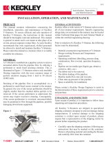
Steam
Trap set
Trap set
Trap set
Steam
Gradient 1:100
Gradient 1:100
30 - 50 metre intervals
Condensate
Condensate
Condensate
Prevention of water hammer
Steam trapping on steam mains:
Steam Mains - Do's and Dont's:
Steam
4
7
7
7
7
4
4
4
Prevention of tensile stressing
Pipe misalignment:
Installing products or re-assembling after maintenance:
Do not over tighten.
Use correct torque gures.
1
1
4 2
3
8
2
6
3
7
Flange bolts should be gradually tightened across
diameters to ensure even load and alignment.
7
4
5
4

3
Installation
1.) Before installing trap, the inlet piping should be care-
fully blown down to remove any existing pipe debris.
CAUTION: Before Installation, inspection or mainte-
nance, ensure that the steam inlet and outlet piping
valves are closed and the trap isolated to prevent per-
sonnel injury.
2.) Check the maximum operating pressure stamped on
the nameplate. If the actual system operating pres-
sure is greater than the maximum operating pressure
of the trap, a trap having a higher operating pressure
must be substituted.
3.) Depending upon the type, trap body pattern will
require either horizontal or vertical piping. Install trap
with bottom and/or arrow cast on trap pointing down-
ward so that the inverted bucket can freely move in a
vertical plane.
4.) Locate the trap below and close to the drain point
where it is accessible for inspection and servic-
ing. A pipeline strainer should be fitted ahead of the
trap along with isolation valves and pipe unions as
required by good piping practices.
5. To prevent backflow, a check valve is recommended
after the trap when condensate is elevated. With a
modulating pressure condition, or on superheated
steam service, a check valve should also be located
ahead of the trap inlet to prevent prime loss.
6. When draining equipment controlled by modulating
valves with vacuum breakers, and whenever greater
air venting capability is desired, an auxiliary thermo-
static air vent should be fitted in parallel above the
trap.
7. Any bypass piping should have reduced capacity and
be installed above the trap to reduce the chance of
prime and steam loss. However, unless continuous
service is necessary, bypass piping should be avoid-
ed whenever possible.
8. On startup, slowly open inlet valve, then outlet valve,
to establish a ‘prime’ or water seal around the inverted
bucket inside the body. If trap does not have enough
startup condensate to ‘prime’ itself, shut if off and
manually pour water into the body. Problems with
‘prime’ loss may indicate that the trap is oversized for
the load and it should be changed to a smaller size.
9.) When installed outdoors, trap will not freeze in con-
tinuous operation but can be damaged if steam pres-
sure is lost or inadvertently turned off. To prevent
freezeup damage, the body must be drained manually
or can be protected automatically with a Spirax Sarco
Thermoton set for 75°F opening temperature.
Inspection and Maintenance
Spirax Sarco Inverted Bucket Traps for horizontal piping
may be inspected and cleaned without removing the trap
from the line. Vertical threaded body types require a union
after the outlet to permit disassembly.
1.) Flash steam - When condensate at steam tempera-
ture is discharged to a lower pressure, part of it re-
evaporates, forming flash steam. This should not be
confused with live steam when inspecting the opera-
tion of steam traps.
2.) To clean or inspect the trap inlet port - Remove
any obstruction or debris from the inlet cavity. If the
trap is fitted with a strainer, make sure the screen
perforations are clear and unobstructed.
3.) To clean, inspect or replace the trap mechanism
a.) Remove the cover bolts and cover.
b.) Remove all dirt and incrustation from the mech-
anism, trap body and cover. Inspect the body
and cover for condensate corrosion.
c.) Inspect the valve head and seat for dam-
age and/or signs of wear or wiredrawing,
and replace is required. To remove the seat,
detach the bucket arm by removing the pin and
unscrew the seat.
d.) Inspect the vent hole in the bucket and make
sure it is clear and fully open.
e.) Remove the old gasket from the cover and/or
body and replace with a new gasket.
f.) Reinstall the cover and mechanism to the trap
body and tighten the cover bolts. It is recom-
mended that the cover bolts be retightened after
the trap has been operating for a few hours
to account for gasket relaxation and thermal
expansion.
Thermal expansion:
Short
distance
Fixing point
Axial movement
Axial movement
Guides
Guides
Guides
Guides
Limit rods
Limit rods
Fixing point
Medium
distance
Small
lateral
movement
Small
lateral
movement
Large
lateral
movement
Large
lateral
movement

4
Bucket Trap Air Vent Head Travel
When installing a bucket trap air vent, the following head
travels are required when set at 70°F to 80°F ambient.
The head travels are measured along the centerline of the
head. The head travels are adjusted by bending the bime-
tallic strip.
B12, B22
Model Travel Tolerance
B12, B22 3/64” +0.000” -1/64”
B32 3/64” ± 1/64”
B42, B52 3/32” ± 1/64”
Hookup for Horizontal Inverted Bucket Trap
Hookup for Vertical
Inverted Bucket Trap
Hookup for SIB
Check Valve
if Condensate
is to be Elevated
Check Valve Required if
Inlet Steam Pressure is
Variable or Superheated
Air Vent if Required
Air Vent if Required
Check Valve if Condensate
is to be Elevated
Bypass
Bypass
Scale
Bimetal
Strip
B32, B42, B52

5
Use high temperature
adhesive/sealant on
air vent seat threads
(Ex. Loctite 272)
Use pipe joint
compound on
screen plug threads
6
2
1a
5
4
(Optional)
3
B12
B22
1b
B32
B42
B52
(Optional)
1
B1, B2
B4, B42, B5, B52
B2, B22, B3, B32
Torque Values (Ft•lbs)
Cover Bolts Size and Models
11-14 1/2”, 3/4” B1X or B1H Series
35-39 3/4” B2 Series
21-24 1” B3 Series
55-59 1-1/4” B4 Series
80-85 2” B5 Series
Valve Seats
11-13 1/2” B1X-75, 125, 180, 250
28-31 1/2”, 3/4” B1H Series; 3/4” B2-7
125, 180, 250; 1/2”, 3/4” B1X-15, 30
46-50 3/4” B2-15, 30; 1” B3-75, 125, 180
66-70 250, 1” B3-15, 30
195-205 1-1/4” B4 Series; 2” B5-75, 125,
180, 250
250-260 2” B5-15, 30
Air Vent Seats
11-14 All Models
Note: Traps with optional strainers use the same cover bolts
and seat torque requirements
Part No. Description
1 Cover
1a Cover Gasket
1b Cover Cap Screws
2 Body
3 Air vent
4 Complete Mechanism
5 Stn. Stl. Bucket
6 Stn. St. Strainer

SPIRAX SARCO, INC. • 1150 NORTHPOINT BLVD. • BLYTHEWOOD, SC 29016
PHONE 803-714-2000 • FAX 803-714-2200
Spirax Sarco Applications Engineering Department
Toll Free at:
1-800-575-0394
Type B Spare Parts List
(TIS 2.407)
1 Cover 4 Complete Mechanism Assembly
1A Gasket 5 Bucket and Hook
1B Cover Bolt 6 Plug Bushing (Strainer Optional)
2 Body
Series HM34 Spare Parts List
(TIS 2.404)
A, B, C, D Valve and Seat Assembly
E Bucket
F, G Cover Gasket and Ferrule
H Strainer Screen
J Strainer Screen Gasket
K Cover Bolts and Nuts
Series 200 Spare Parts List
(TIS 2.401)
A, B, C, D Valve and Seat Assembly
G Bucket
J Internal Tube
K Cover Gasket
L Cover Studs and Nuts
Series 600 and 900 Spare Parts
(TIS 2.402, 2.403)
A, B, C, D Valve and Seat Assembly
G Bucket
H, J Check Valve Assembly
K Cover Gasket
L Cover Studs and Nuts
Series SIB
(TIS 2.407)
No user serviceable parts.
1B
1
4
5
6
1A
2
F, G
A, B, C, D
J
H
K
E
K
L
J
L
K
H, J
G
A, B, C, D
G
A, B, C, D
-
 1
1
-
 2
2
-
 3
3
-
 4
4
-
 5
5
-
 6
6


Ask a question and I''ll find the answer in the document
Finding information in a document is now easier with AI
Related papers
-
Spirax Sarco Drip Pan Elbow Installation And Maintenance Instructions
-
-
Spirax Sarco 65743 Installation guide
-
-
Spirax Sarco IPC 20 and IPC 21 Pipeline Connectors Installation guide
-
-
-
-
-
Spirax Sarco 66190 Installation guide
Other documents
-
Hubbell STH User manual
-
Watts WIB-80-20 3/4 Installation guide
-
Yarway Series 711, 731, 746 and 751-F2 Unibody Plus Steam Traps Owner's manual
-
Armstrong SH-2000 Operating instructions
-
-
-
-
Stero Dishwashers STW User manual
-
 Keckley 3/41THY-BCM20M34-FTI-F150 Installation guide
-
Condair 2552940-E SE Series Installation guide
