Page is loading ...

FREE FLOAT TYPE STEAM TRAPS
SS1NL/SS1NH/SS1VL/SS1VH
SS1VL/SS1VHSS1NL/SS1NH
INSTRUCTION MANUAL
Keep this manual in a safe place for future reference
Copyright (C) 2015 by TLV Co., Ltd. All rights reserved.
881 Nagasuna, Noguchi, Kakogawa, Hyogo 675-8511, Japan
Manufacturer
Tel: [81]-(0)79-422-1122Fax: [81]-(0)79-422-0112

1. Safety Considerations
• Read this section carefully before use and be sure to follow the instructions.
• Installation, inspection, maintenance, repairs, disassembly, adjustment and valve
opening/closing should be carried out only by trained maintenance personnel.
• The precautions listed in this manual are designed to ensure safety and prevent equipment
damage and personal injury. For situations that may occur as a result of erroneous handling,
three different types of cautionary items are used to indicate the degree of urgency and the
scale of potential damage and danger: DANGER, WARNING and CAUTION.
• The three types of cautionary items above are very important for safety; be sure to observe
all of them, as they relate to installation, use, maintenance, and repair. Furthermore, TLV
accepts no responsibility for any accidents or damage occurring as a result of failure to
observe these precautions.
Indicates an urgent situation
which poses a threat of
death or serious injury.
Indicates that there is a
potential threat of death
or serious injury.
WARNING
CAUTION
WARNING
DANGER CAUTION
Indicates that there is a
possibility of injury or equip-
ment/product damage.
NEVER apply direct heat to the float. The float may explode due to
increased internal pressure, causing accidents leading to serious injury
or damage to property and equipment.
Install properly and DO NOT use this product outside the
recommended operating pressure, temperature and other specification
ranges. Improper use may result in such hazards as damage to the product
or malfunctions, which may lead to serious accidents. Local regulations
may restrict the use of this product to below the conditions quoted.
Take measures to prevent people from coming into direct contact
with product outlets. Failure to do so may result in burns or other injury
from the discharge of fluids.
DO NOT use this product in excess of the maximum operating
pressure differential. Such use could make discharge impossible.
Do not subject this product to condensate loads that exceed its
discharge capacity. Failure to observe this precaution may lead to
condensate accumulation upstream of the trap, resulting in reduced
equipment performance or damage to the equipment.
Introduction
Before beginning installation or maintenance, please read this manual to ensure correct use of
the product. Keep the manual in a safe place for future reference.
The all stainless steel Free Float steam traps of the SS1 series, with bimetal thermostatic air vent,
are suitable for a wide range of small to medium capacity applications up to 2.1 MPaG (300 psig),
such as steam mains, tracer lines, small process applications, etc. The traps discharge
condensate continuously and automatically, at a temperature slightly lower than saturation
temperature.
1 MPa = 10.197 kg/cm
2
, 1 bar = 0.1 MPa
For products with special specifications or with options not included in this manual, contact TLV
for instructions.
The contents of this manual are subject to change without notice.
Continued on next page

CAUTION
When disassembling or removing the product, wait until the internal
pressure equals atmospheric pressure and the surface of the
product has cooled to room temperature. Disassembling or removing
the product when it is hot or under pressure may lead to discharge of
fluids, causing burns, other injuries or damage.
Be sure to use only the recommended components when repairing
the product, and NEVER attempt to modify the product in any way.
Failure to observe these precautions may result in damage to the product
or burns or other injury due to malfunction or the discharge of fluids.
Use only under conditions in which no freeze-up will occur. Freezing
may damage the product, leading to fluid discharge, which may cause
burns or other injury.
Use under conditions in which no water hammer will occur. The
impact of water hammer may damage the product, leading to fluid
discharge, which may cause burns or other injury.
2. Specifications
To avoid malfunctions, product damage, accidents or serious injury,
install properly and DO NOT use this product outside the specification
range. Local regulations may restrict the use of this product to below the
conditions quoted.
CAUTION
Refer to the product nameplate for detailed specifications.
* Maximum allowable pressure (PMA) and maximum allowable temperature (TMA) are
PRESSURE SHELL DESIGN CONDITIONS, NOT OPERATING CONDITIONS.
** "Valve No." is displayed for products with options. This item is omitted from the
nameplate when there are no options.
A Model
B Nominal Diameter
C Maximum Allowable Pressure*
D
Maximum Allowable Temperature* TMA
E Maximum Differential Pressure
F Maximum Operating Temperature
G
Production Lot No.
H Valve No.**
A
B
D
F
G
G
D
E
B
C
A
C
F
H
E
H

SS1NL/SS1NH
Horizontal
SS1VL/SS1VH
Vertical
3. Configuration
14 1 63
12 13
7
8
2 9 4 511 10
11 10
7
8
2
9
11
10
4
5
12
14
1
6
11
3
13
10
* M = Maintenance Kit; R = Repair Kit; F = Float; replacement
parts are available only in their respective kits
** Includes attached float guides for SS1VL/SS1VH
No.
1
2
3
4
5
6
7
Body
Cover**
Float
Orifice
Orifice Gasket
Screen
Cover Gasket
Description
M*
-
-
-
-
-
R*
-
-
-
F*
-
-
-
-
-
-
No.
8
9
10
11
12
13
14
Cover Bolt
Bimetal Air Vent Strip
Screw
Spring Washer
Nameplate
Connector
Pipe/Flange
Description
M*
-
-
-
-
-
-
-
R*
-
-
-
-
F*
-
-
-
-
-
-
-

SS1NL/SS1NH SS1VL/SS1VH
4. Exploded View
1110
13
2
8
9
4
5
3
7
6
1
1
7
1110
2
8
2
9
6
3
4
5
13

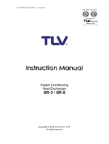
6. Piping Arrangement
Requirement
Install a catchpot with the
proper diameter.
Diameter is too
small.
Diameter is too
small and inlet
protrudes into pipe.
Rust and scale
flow into the trap
with the
condensate.
Condensate
collects in the
pipe.
Continued on the next page
Make sure the flow of
condensate is not
obstructed.
To prevent rust and scale
from flowing into the trap,
connect the inlet pipe
25 - 50 mm (1 - 2 in) above
the base of the T - pipe.
When installing on the
blind end, make sure
nothing obstructs the flow
of condensate.
Correct
Incorrect
Allowable lnclination
SS1NL/SS1NH SS1VL/SS1VH
1.
Before installation, be sure to remove all protective seals.
2.
Before installing the trap, blow out the inlet piping to remove all dirt and oil.
3. Install the steam trap within the allowable inclination, as shown below. Also make sure that
the arrow mark on the body corresponds with the direction of flow.
4.
Install the trap in the lowest part of the pipeline or equipment so the condensate flows naturally
into the trap by gravity. The inlet pipe should be as short and have as few bends as possible.
5.
Support the pipes properly within 800 mm (2.5 ft) on either side of the trap.
6.
Install a bypass valve to discharge condensate, and inlet and outlet valves to isolate the trap in
the event of trap failure or when performing maintenance.
7.
Install a check valve at the trap outlet whenever more than one trap is connected to the
condensate collection pipeline.
8.
The use of unions is recommended to facilitate connection and disconnection of screwed
models.
5. Proper Installation
• Installation, inspection, maintenance, repairs, disassembly, adjustment
and valve opening/closing should be carried out only by trained
maintenance personnel.
• Take measures to prevent people from coming into direct contact with
product outlets.
• Install for use under conditions in which no freeze-up will occur.
• Install for use under conditions in which no water hammer will occur.
CAUTION
5˚5˚
5˚5˚
5˚5˚5˚5˚

1. Is the pipe diameter suitable?
2. Has the trap been installed within the allowable inclination and with the arrow on the body
pointing in the direction of flow?
3. Has sufficient space been secured for maintenance?
4. Have maintenance valves been installed at the inlet and outlet? If the outlet is subject to
back pressure, has a check valve been installed?
5. Is the inlet pipe as short as possible, with as few bends as possible, and installed so that the
condensate will flow naturally down into the trap?
6. Has the piping work been done with the proper methods, as shown in the table on page 5?
Check to make sure that the pipes connected to the trap have been installed properly.
7. Operational Check
Normal: Condensate is discharged continuously with flash steam and the sound
of flow can be heard. If there is very little condensate, there is almost no
sound of flow.
Blocked: No condensate is discharged. The trap is quiet and makes no noise,
and the surface temperature of the trap is low.
Blowing: Live steam continually flows from the outlet and there is a continuous
metallic sound.
Live steam is discharged through the trap outlet together with the
condensate and there is a high-pitched sound.
A visual inspection can be carried out to aid in determining the necessity for immediate
maintenance or repair, if the trap is open to atmosphere. If the trap does not discharge to
atmosphere, use diagnostic equipment such as TLV TrapMan or TLV Pocket TrapMan.
White jet
containing
water droplets
Clear, slightly
bluish jet
(When conducting a visual inspection, flash steam is sometimes mistaken for steam leakage. For
this reason, the use of a steam trap diagnostic instrument such as TLV TrapMan is highly
recommended.)
Steam
Leakage:
Flash Steam
Live Steam Leakage
Operational inspections should be performed at least twice per year, or as called for by trap
operating conditions. Steam trap failure may result in temperature drop in the equipment, poor
product quality or losses due to steam leakage.
8. Inspection and Maintenance
WARNING
NEVER apply direct heat to the float. The float may explode due to
increased internal pressure, causing accidents leading to serious injury or
property and equipment damage.
• Installation, inspection, maintenance, repairs, disassembly, adjustment
and valve opening/closing should be carried out only by trained
maintenance personnel.
• Before attempting to open the trap, close the inlet and outlet isolation
valves and wait until the trap has cooled completely. Failure to do so
may result in burns.
• Be sure to use the proper components and NEVER attempt to modify
the product.
CAUTION

Body, Cover
Gaskets
Air Vent Strip
Screen
Float
Orifice
Check inside for damage, dirt, grease, oil film, rust or scale
Check for warping or damage
Check for damage
Check for clogging, corrosion or damage
Check for deformation, damage, oil film or water inside
Check for rust, scale, oil film, wear or damage
Parts Inspection Procedure
Figure A Figure B
Screw &
Washer
Screen
Float Guides
Connector
Cover Gasket
Note: Do not change the
position of the float
guides. Tight sealing
cannot be guaranteed
if the float guides have
been moved out of
position.
During Disassembly During Reassembly
SS1NL/SS1VL:
Remove if damaged
SS1NH/SS1VH:
Remove gasket and clean sealing
surfaces of cover and body
Replace with a new gasket, do not apply
anti-seize
Replace with a new gasket if worn or
damaged
Coat threads with anti-seize and
tighten to the proper torque
Remove connector
Apply anti-seize to both sides and
replace with a new gasket
Remove with a socket wrench
Reinstall connector
Remove gasket and clean sealing
surfaces
Remove, being careful not to
scratch its polished surface
Part & No.
Cover 2
Cover Gasket 7
Connector 13
Remove the screw with a Philips
screwdriver, then remove the air
vent strip without bending
Reinstall air vent strip without bending;
tighten screw to the proper torque
Air Vent strip 9
(with Screw 10
and Washer 11)
Orifice 4
Orifice Gasket 5
Float 3
Remove with a socket wrench Coat threads with anti-seize and
tighten to the proper torque
Cover Bolt 8
Disassembly / Reassembly (to reassemble, follow procedures in reverse)
Remove carefully; take care to
prevent any damage to the float,
which may fall out when the cover
is removed
Make sure the sealing surfaces are clean
and then reattach; be careful not to bend
the float guides (SS1VL/SS1VH only);
(Fig. A)
Place inside the body (or on the cover), being
careful not to scratch its polished surface
Remove the 2 screws with a Philips
screwdriver, then remove the
screen without bending
Screen 6
(with Screws 10
and Washers 11)
Remove any scale build-up on the surface and
then reassemble (Fig. B); tighten screws to the
proper torque.
Cover Bolt 8
Tightening Torque and Distance Across Flats
mm (in)(lbf
.
ft)
N
.
m
(33)
45
17
( )
Orifice 4
mm (in)(lbf
.
ft)
N
.
m
(15)
20
( )
13
Screw 10
mm (in)(lbf
.
ft)
N
.
m
(0.22)
0.3
+ (+)
1 N
.
m 10 k g
·
cm
If drawings or other special documentation were supplied for the product, any torque given there
takes precedence over values shown here.
32
21
/
2
1
/

9.
Instructions for Plug / Holder Disassembly and Reassembly
The seal on the threaded plugs/holders found on TLV products is formed by a flat metal
gasket. There are various installation orientations for the gaskets, such as horizontal,
diagonal and downward, and the gasket may be pinched in the thread recesses during
assembly.
Instructions for Disassembly and Reassembly
1 Remove the plug/holder using a tool of the specified
size (distance across flats).
2 The gasket should not be reused. Be sure to
replace it with a new gasket.
3 Clean the gasket surfaces of the plug/holder and the
product body using a rag and/or cleaning agents, then
check to make sure the surfaces are not scratched or
deformed.
4 Coat both the gasket surface of the plug/holder and
the threads of the plug/holder with anti-seize, then
press the gasket onto the center of the gasket
surface of the plug/holder, making sure the
anti-seize affixes the gasket tightly to the
plug/holder. Check to make sure the gasket is not
caught in the recesses of the threads.
5 Hold the plug/holder upside down to make sure that
the anti-seize makes the gasket stick to the
plug/holder even when the plug/holder is held
upside down.
6 Screw the plug/holder by hand into the product body
while making sure that the gasket remains tightly
affixed to the center of the gasket surface of the
plug/holder. Make sure the entire gasket is making
contact with the gasket surface of the product body.
It is important at this point to make sure the gasket
is not pinched in the thread recesses of the
plug/holder.
7 Tighten the plug/holder to the proper torque.
8 Next, begin the supply of steam and check to make sure there is no leakage from the part
just tightened. If there is leakage, immediately close the inlet valve and, if there is a bypass
valve, take the necessary steps to release any residual pressure. After the surface of the
product cools to room temperature, repeat the procedure beginning from step 1 .
3
5
6
Gasket
Do not pinch gasket
in thread recesses
4
Coat with anti-seize
Gasket Surface

10. Troubleshooting
If the expected performance is unachievable after installation of the steam trap, read chapters 5
and 6 again and check the following points for appropriate corrective measures.
Problem
No condensate
is discharged or
discharge is
poor (blocked)
Steam is
discharged or
leaks from the
trap outlet
(blowing)
(steam leakage)
Steam leaks
from a place
other than the
trap outlet
Float is damaged or filled with
condensate
The trap operating pressure exceeds
the maximum specified pressure, or
there is insufficient differential pressure
between the trap inlet and outlet
Compare specifications and actual
operating conditions
Steam-locking has occurred
Flow exceeds trap’s rated capacity
Blowdown through the bypass or
close the trap inlet valve and allow
the trap to cool
Check specifications and reselect
trap suitable for actual flow
Clean
Deterioration of or damage to gaskets
Replace with new gaskets
Float is
frequently
damaged
Water hammer occurs
Examine the piping for
problems that can cause
water hammer
The Orifice is damaged Replace with new valve seat
Float is deformed or coated with scale Clean or replace the float
Trap is installed above the maximum
allowable inclination angle
Correct the installation
Vibration of trap occurs Lengthen inlet piping, then fasten it
securely
The air vent strip is damaged Replace with a new air vent strip
Replace with new float
Cause Remedy
The float is sticking to the valve seat
Tighten to the proper torque
Orifice, screen or piping is
clogged with rust or scale
Rust and scale have accumulated
around the valve seat or under the float
Clean
Clean
Improper tightening torque for cover
was used
NOTE: When replacing parts with new, use the parts list on page 3 for reference, and replace with
parts from the respective replacement parts kits.

11.
Express Limited Warranty
Subject to the limitations set forth below, TLV Corporation, a North Carolina corporation (“TLV”)
warrants that products which are sold by it or TLV International, Inc., a Japanese corporation
(“TII”), which products (the “Products”) are designed and manufactured by TLV Co., Ltd., a
Japanese corporation (“TLVJ”), conform to the specifications published by TLV for the
corresponding part numbers (the “Specifications”) and are free from defective workmanship
and materials. With regard to products or components manufactured by unrelated third parties
(the “Components”), TLV provides no warranty other than the warranty from the third party
manufacturer(s).
Duration Of Warranty
This warranty is effective for a period of the earlier of: (i) three (3) years after delivery of Products
to the first end user in the case of sealed SST-Series Products for use in steam pressure service
up to 650 psig; (ii) two (2) years after delivery of Products to the first end user in the case of
PowerTrap
®
units; or (iii) one (1) year afterdelivery of Products to the first end user in the case of
all other Products. Notwithstanding the foregoing, asserting a claim under this warranty must be
brought by the earlier of one of the foregoing periods, as applicable, or within five (5) years after
the date of delivery to the initial buyer if not sold initially to the first end user.
ANY IMPLIED WARRANTIES NOT NEGATED HEREBY WHICH MAY ARISE BY OPERATION OF
LAW, INCLUDING THE IMPLIED WARRANTIES OF MERCHANTABILITY AND FITNESS FOR A
PARTICULAR PURPOSE AND ANY EXPRESS WARRANTIES NOT NEGATED HEREBY, ARE
GIVEN SOLELY TO THE INITIAL BUYER AND ARE LIMITED IN DURATION TO ONE (1) YEAR
FROM THE DATE OF SHIPMENT BY TLV.
Exclusive Remedy
THE EXCLUSIVE REMEDY UNDER THIS WARRANTY, UNDER ANY EXPRESS WARRANTY OR
UNDER ANY IMPLIED WARRANTIES NOT NEGATED HEREBY (INCLUDING THE IMPLIED
WARRANTIES OF MERCHANTABILITY AND FITNESS FOR A PARTICULAR PURPOSE), IS
REPLACEMENT; PROVIDED: (a) THE CLAIMED DEFECT IS REPORTED TO TLV IN WRITING
WITHIN THE APPLICABLE WARRANTY PERIOD, INCLUDING A DETAILED WRITTEN
DESCRIPTION OF THE CLAIMED DEFECT AND HOW AND WHEN THE CLAIMED DEFECTIVE
PRODUCT WAS USED; AND (b) THE CLAIMED DEFECTIVE PRODUCT AND A COPY OF THE
PURCHASE INVOICE IS RETURNED TO TLV, FREIGHT AND TRANSPORTATION COSTS
PREPAID, UNDER A RETURN MATERIAL AUTHORIZATION AND TRACKING NUMBER ISSUED
BY TLV. ALL LABOR COSTS, SHIPPING COSTS, AND TRANSPORTATION COSTS
ASSOCIATED WITH THE RETURN OR REPLACEMENT OF THE CLAIMED DEFECTIVE
PRODUCT ARE SOLELY THE RESPONSIBILITY OF BUYER OR THE FIRST END USER. TLV
RESERVES THE RIGHT TO INSPECT ON THE FIRST END USER'S SITE ANY PRODUCTS
Exceptions To Warranty
This warranty does not cover defects or failures caused by:
1. improper shipping, installation, use, handling, etc., by other than TLV or service
representatives authorized by TLV; or
2. dirt, scale or rust, etc.; or
3. improper disassembly and reassembly, or inadequate inspection and maintenance by other
than TLV or service representatives authorized by TLV; or
4. disasters or forces of nature; or
5. abuse, abnormal use, accidents or any other cause beyond the control of TLV; or
6. improper storage, maintenance or repair; or
7. operation of the Products not in accordance with instructions issued with the Products or
with accepted industry practices; or
8. use for a purpose or in a manner for which the Products were not intended; or
9. use of the Products in a manner inconsistent with the Specifications; or
10. failure to follow the instructions contained in the TLV Instruction Manual for the Product.

CLAIMED TO BE DEFECTIVE BEFORE ISSUING A RETURN MATERIAL AUTHORIZATION.
SHOULD SUCH INSPECTION REVEAL, IN TLV’S REASONABLE DISCRETION, THAT THE
CLAIMED DEFECT IS NOT COVERED BY THIS WARRANTY, THE PARTY ASSERTING THIS
WARRANTY SHALL PAY TLV FOR THE TIME AND EXPENSES RELATED TO SUCH ON-SITE
INSPECTION.
Exclusion Of Consequential And Incidental Damages
IT IS SPECIFICALLY ACKNOWLEDGED THAT THIS WARRANTY, ANY OTHER EXPRESS
WARRANTY NOT NEGATED HEREBY, AND ANY IMPLIED WARRANTY NOT NEGATED
HEREBY, INCLUDING THE IMPLIED WARRANTIES OF MERCHANTABILITY AND FITNESS
FOR A PARTICULAR PURPOSE, DO NOT COVER, AND NEITHER TLV, TII NOR TLVJ WILL IN
ANY EVENT BE LIABLE FOR, INCIDENTAL OR CONSEQUENTIAL DAMAGES, INCLUDING,
BUT NOT LIMITED TO LOST PROFITS, THE COST OF DISASSEMBLY AND SHIPMENT OF
THE DEFECTIVE PRODUCT, INJURY TO OTHER PROPERTY, DAMAGE TO BUYER’S OR THE
FIRST END USER’S PRODUCT, DAMAGE TO BUYER’S OR THE FIRST END USER’S
PROCESSES, LOSS OF USE, OR OTHER COMMERCIAL LOSSES. WHERE, DUE TO
OPERATION OF LAW, CONSEQUENTIAL AND INCIDENTAL DAMAGES UNDER THIS
WARRANTY, UNDER ANY OTHER EXPRESS WARRANTY NOT NEGATED HEREBY OR
UNDER ANY IMPLIED WARRANTY NOT NEGATED HEREBY (INCLUDING THE IMPLIED
WARRANTIES OF MERCHANTABILITY AND FITNESS FOR A PARTICULAR PURPOSE)
CANNOT BE EXCLUDED, SUCH DAMAGES ARE EXPRESSLY LIMITED IN AMOUNT TO THE
PURCHASE PRICE OF THE DEFECTIVE PRODUCT. THIS EXCLUSION OF CONSEQUENTIAL
AND INCIDENTAL DAMAGES, AND THE PROVISION OF THIS WARRANTY LIMITING
REMEDIES HEREUNDER TO REPLACEMENT, ARE INDEPENDENT PROVISIONS, AND ANY
DETERMINATION THAT THE LIMITATION OF REMEDIES FAILS OF ITS ESSENTIAL
PURPOSE OR ANY OTHER DETERMINATION THAT EITHER OF THE ABOVE REMEDIES IS
UNENFORCEABLE, SHALL NOT BE CONSTRUED TO MAKE THE OTHER PROVISIONS
UNENFORCEABLE.
Exclusion Of Other Warranties
THIS WARRANTY IS IN LIEU OF ALL OTHER WARRANTIES, EXPRESS OR IMPLIED, AND ALL
OTHER WARRANTIES, INCLUDING BUT NOT LIMITED TO THE IMPLIED WARRANTIES OF
MERCHANTABILITY AND FITNESS FOR A PARTICULAR PURPOSE, ARE EXPRESSLY
DISCLAIMED.
Severability
Any provision of this warranty which is invalid, prohibited or unenforceable in any jurisdiction
shall, as to such jurisdiction, be ineffective to the extent of such invalidity, prohibition or
unenforceability without invalidating the remaining provisions hereof, and any such invalidity,
prohibition or unenforceability in any such jurisdiction shall not invalidate or render
unenforceable such provision in any other jurisdiction.
13901 South Lakes Drive, Charlotte, NC 28273-6790, U.S.A.
Tel: [1]-704-597-9070 Fax: [1]-704-583-1610
Rev. 1/2015 (M)
Printed on recycled paper.
/