Page is loading ...

© 2017 UTC Fire & Security Americas Corporation, Inc. 1 / 4 P/N 466-2935 • REV A • ISS 12SEP17
ShatterPro II Advanced Acoustic Sensor with
Pattern Recognition Technology Installation
Instructions
SEE PAGE 3 FOR IMPORTANT WARNINGS, DISCLAIMERS,
AND PRODUCT/SAFETY INFORMATION.
Introduction
This is the 5822A-W ShatterPro II Advanced Acoustic Sensor
Installation Instructions. The ShatterPro II sensor is designed
to detect breaking glass from framed windows in the perimeter
of a building.
Install the sensors on a perimeter loop armed whenever the
door and window contacts are armed. To prevent false alarms,
avoid applications where glassbreak sensors are configured to
be active in all arming levels.
The sensor false alarm immunity technology functions best in
rooms with only moderate noise. Some sounds can duplicate
the points on the glassbreak pattern the sensors detect.
The sensors may not consistently detect cracks in glass or
bullets that break through the glass. Always complement
glassbreak sensors with interior protection.
Connect the sensors to a UL Listed control panel, or a power
supply that provides at least four hours of standby power.
Mounting location
You can mount the sensors on the ceiling or on a wall.
Wall mount
The best wall-mount location is on the wall opposite to the
glass to be protected, assuming this glass is within the sensor
range and line of sight. You can also use the adjoining wall.
Ceiling mount
Mount the sensors in a location that is in direct line of sight of
the glass to be protected. However, since sound travels out
from a broken window, a position 8 ft. (2.4 m) into the room
provides better detection.
The mounting location can affect sensor detection ability. To
ensure optimum performance, the coverage zone width should
be no greater than two times the distance from the sensor to
the closest point of glass. For instance, if a sensor is mounted
10 ft. (3 m) from the glass, its optimum performance zone will
be 10 ft. (3 m) in either direction of the midpoint. You can
mount the sensors from 3.3 to 25 ft. (1 to 7.6 m) from the
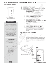
farthest point of the glass. Figure 1 below shows the coverage
zone with D being the distance from the glass.
Figure 1: Coverage zone
Use the following guidelines to determine the best mounting
location:
• Mount the sensors at least 3.3 ft. (1 m) from the windows
being protected and at least 4 ft. (1.2 m) from noise
sources such as TV’s, speakers, sinks and doors.
• Mount the sensors in the direct line of sight of the glass to
be protected.
• Avoid rooms smaller than 10 by 10 ft. (3 m by 3 m).
• Avoid locations where lined, insulating, or sound
deadening drapes or closed wooden shutters are used.
• Mount the sensors in a suitable environment: temperature
between 0 and 120°F (−18 and 50°C); and humidity
between 10 and 90% noncondensing. Do not install the
sensors in humid rooms. Excess moisture on the circuit
boards can eventually cause a short and a false alarm.
• Mount the sensors on a stable surface up to 25 ft. (7.6 m)
from the farthest point on the glass surface.
D D
Optimum
detection
zone
D is distance from glass.
The optimum performance zone
is distance D in either direction
on the glass.
ShatterPro
D
2
5
f
t
.

2 / 4 P/N 466-2935 • REV A • ISS 12SEP17
• Avoid locations that expose the sensors to possible false
alarm sources such as:
- Glass airlocks and vestibule areas
- Kitchens
- Corner mountings
- Residential car garages
- Small utility rooms
- Stairwells
- Bathrooms
- Small acoustically live rooms
Coverage range
The sensors are omnidirectional, providing 360° coverage.
Coverage is measured from a sensor to the point on the glass
farthest from the sensor. The sensors can be mounted as
close as 3.3 ft. (1 m) from the glass. The maximum range
depends on the type of glass being protected:
Armor-coated glass
Mount the sensors no more than 12 ft. (3.65 m) from the glass.
Plate, tempered, laminated, and wired glass
When the sensors are mounted on the ceiling or the opposite
or adjoining wall, (Figure 2 below) maximum range is 25 ft.
(7.5 m).
Figure 2: Maximum coverage range
Testing
Test the sensor upon installation and if the window glass-type
is changed.
The sensors are designed to detect the breaking of framed
glass mounted in an outside wall. Testing the sensors with
unframed glass, broken bottles, etc., may not trip the sensors.
The sensors typically do not trip to glass breaking in the middle
of the room. To verify sensor range and operation, you need to
use the UTC Fire & Security 5709C hand-held tester.
Test mode
To put the sensors in test mode, do the following:
1. Connect a 9-volt battery to the sensor for pretesting.
2. Temporarily mount sensor in the desired location.
3. Use the 5709C hand-held tester to put the sensor into test
mode. Set the tester to tempered glass and hold the tester
on top of the sensor (Figure 3 below). Activate the tester,
this will trip the sensor into test mode for one minute. In
test mode, the LED will blink continuously. To extend test
time, activate the tester at least once a minute.
When the system is armed and the sensor trips to an alarm
condition, the LED will light solid for four seconds and then
revert back to a one minute test mode. At the end of one
minute, the LED will extinguish if it is in set up LED mode, or
the LED will light if it is in latching LED mode.
Figure 3: Activating test mode
Sensor test
Before you can test the sensors, they must be in test mode
(blinking). To test the sensors, do the following:
1. Choose the laminated setting on the tester.
2. Hold the tester near the surface of the glass to be
protected and aim the speaker at the sensor. Be sure the
tester is at the point on the glass farthest from the sensor.
If closed drapes or curtains are present, hold the tester
behind them (Figure 4 below).
Figure 4: Testing behind curtains
3. Press the test button on the tester. The LED on the sensor
should stay on for four seconds to indicate the glass is
within detection range of the sensor. If the LED does not
stay on for four seconds, move the sensor and retest.
For latching LED, provide a power reset by removing power
and resetting the LED.
25 ft. (7.5 m)
2
5
f
t
.
(
7
.
5
m
)
Hold tester so that the speaker is
within 1 inch of sensor microphone.
In test mode the sensor LED will light
solid for about 4 seconds,
then blink for about a minute.
1 inch

P/N 466-2935 • REV A • ISS 12SEP17 3 / 4
Installation
All wiring must conform to the National Electric Code (NEC)
and/or local codes having jurisdiction.
Do not install sensors in rooms with ultrasonic sensors.
To mount the sensor on a wall or ceiling, do the following:
1. Drill a 1 in. (2.5 cm) hole. For hard woods, drill a 1 1/16 in.
(2.7 cm) hole. For a cleaner hole, use a spade bit rather
than a twist bit.
2. Run wires through the hole and the sleeve to the sensor.
3. Connect wires to the wire terminals as shown in “Wiring”
below.
4. Insert the sleeve into the mounting hole and insert the
sensor into the sleeve, matching the ribs on the sensor
with the grooves on the sleeve.
Wiring
Strip back the outer jacket on your wiring cable. This allows
wires to flex in the case. Make sure the cable is slack in the
wall to avoid stressing the wires at their connections.
Figure 5 below shows the wiring terminals for ShatterPro II.
Figure 5: ShatterPro II wiring terminals
Maintenance
When installed and used properly, minimal maintenance is
required. You should test the sensors annually to ensure
proper operation.
Clean the covers with a damp (water) cloth as needed to keep
it free of dust and dirt. Always test the sensors after cleaning
them.
Specifications
Voltage
9 to 16 VDC
Current:
Typical
Maximum
15 mA
25 mA
Relay output:
On resistance
Off resistance
Normally closed, open 4 seconds upon alarm
10 Ω −5 +10
> 1 MΩ
Maximum loop rating
16 VDC, 50 mA (relay)
Detection range
3.3 to 25 ft. (1 to 7.5 m) , 360°
Minimum glass size
12 by 24 in. (0.3 by 0.6 m)
Recommended glass
thickness:
Plate
Tempered
Wired
Laminated
3/32 to 1/4 in. (2.4 to 6.4 mm)
1/8 to 1/4 in. (3.2 to 6.4 mm)
1/4 in. (6.4 mm)
1/8 to 1/4 in. (3.2 to 6.4 mm)
Operating temperature
0 to 120°F (−18 to 50°C)
Relative humidity
10 to 90% noncondensing
Microphone
Omnidirectional electret
Color
White
Wiring terminals
14-22 AWG
Regulatory information
Manufacturer
UTC Fire & Security Americas Corporation, Inc.
3211 Progress Drive, Lincolnton, NC, 28092, USA
AUTHORIZED EU REPRESENTATIVE:
UTC Fire & Security B.V.
Kelvinstraat 7, 6003 DH Weert, Netherlands
Copyright
Copyright © 2017 United Technologies
Corporation. All rights reserved.
Trademarks
Interlogix is a registered trademark of United
Technologies Corporation. Interlogix is part of
UTC Climate, Controls & Security, a unit of United
Technologies Corporation.
Warnings and
Disclaimers
These products are intended for sale to, and
installation by, an experienced security
professional. UTC Fire & Security cannot provide
any assurance that any person or entity buying its
products, including any “authorized dealer,” is
properly trained or experienced to correctly install
security related products.
For more information on product warnings, refer
to www.utcfssecurityproducts.eu/productwarning/
or scan the code.
Certification
FCC/IC
This equipment has been tested and found to
comply with the limits for a Class B digital device,
pursuant to Part 15 of the FCC Rules. These
limits are designed to provide reasonable
protection against harmful interference in a
residential installation.
This equipment generates, uses, and can radiate
radio frequency energy and, if not installed and
used in accordance with the instructions, may
cause harmful interference to radio
communications. However, there is no guarantee
that interference will not occur in a particular
installation.
If this equipment does cause harmful interference
to radio or television reception, which can be
determined by turning the equipment off and on,
the user is encouraged to try to correct the
interference by one or more of the following
measures:
- Reorient or relocate the receiving antenna.
- Increase the separation between the
equipment and receiver.
- Connect the equipment into an outlet on a
circuit different from that to which the
Cut for
latching LED

4 / 4 P/N 466-2935 • REV A • ISS 12SEP17
receiver is connected.
- Consult the dealer or an experienced
radio/TV technician for help.
Changes or modifications not expressly approved
by UTC Fire and Security could void the user’s
authority to operate the equipment.
This device complies with Industry Canada
license-exempt RSS standard(s). Operation is
subject to the following two conditions: (1) this
device may not cause interference, and (2) this
device must accept any interference, including
interference that may cause undesired operation
of the device.
Cet appareil est conforme avec Industrie Canada
exempts de licence standard RSS (s). Son
fonctionnement est soumis aux deux conditions
suivantes: (1) cet appareil ne doit pas provoquer
d'interférences et (2) cet appareil doit accepter
toute interférence, y compris celles pouvant
causer un mauvais fonctionnement de l'appareil.
UTC Fire & Security hereby declares that this
device is in compliance with the applicable
requirements and provisions of the Directive
2014/30/EU, 2014/35/EU, and 2011/65/EU. For
more information see www.utcfireandsecurity.com
or www.interlogix.com.
2012/19/EU (WEEE directive): Products marked
with this symbol cannot be disposed of as
unsorted municipal waste in the European Union.
For proper recycling, return this product to your
local supplier upon the purchase of equivalent
new equipment, or dispose of it at designated
collection points. For more information see:
www.utcfssecurityproducts.eu/recycle/
Product ordering
Product
Description
5822A-W
Recessed ShatterPro II, latch or nonlatch LED
Accessories
5709C-W
Glassbreak hand-held tester
Contact information
www.interlogix.com
For customer support, see www.interlogix.com/customer-
support
/