Page is loading ...

ISSUE DATE:
3/19/96
ISSUE:
B
S
CALE:
Not to scale
5633K
5635K
5636K
5637K
Silicone Rubber Termination Kits
for Single Conductor Tape Shielded,
Wire Shielded or UniShielded
Cables
Quick Term II
78–8114–1266–3
10NUMBER OF PAGES:
Tape Shield
Wire Shield
UniShield
UniShield
is a registered trademark of BICC Corporation
Cold ShrinkSilicone Rubber Termination
(With High-K Stress Relief)
Instruction Sheet
Quick Term II
IEEE Std. No. 48–1990
Class 1 Termination
15 kV Class
110 kV BIL
Kit Contents:
3 Hi–K Silicone Rubber Terminations
3 Mechanical Ground Strap Assemblies
3 Strips Sealing Mastic
(black with white release liners, bagged)
1 Roll of Scotch 13 Semi-Conducting Tape
1 Roll of Scotch 70 Silicone Rubber Tape
3 Packs of Silicone Grease
(clear 5cc tube with green letters)
1 Scotch Cable Preparation Kit
1 Instruction Sheet
5 to 15 kV Kit Selection Chart
NOTE: Final determining factor is cable insulation diameter
Kit
Cable
Insulation O D
Cable Jacket
Conductor Size Range (AWG & kcmil)
Number
Ins
u
lation
O
.
D
.
Range
O.D. Range
5 kV 8 kV 100% 8 kV 133% 15 kV 100% 15 kV 133%
5633K
0.64 – 0.90 in.
(16,3 – 22,9 mm)
0.80 – 1.20 in.
(20,3 – 30,5 mm)
3/0 – 300 2/0 – 250 1/0 – 4/0 2 – 3/0 4 – 1/0
5635K
0.84 – 1.33 in.
(21,3 – 33,8 mm)
1.00 – 1.60 in.
(25,4 – 40,6 mm)
350 – 750 300 – 750 250 – 600 3/0 – 500 2/0 – 350
5636K
1.10 – 1.65 in.
(27,9 – 41,9 mm)
1.30 – 1.90 in.
(33,0 – 48,3 mm)
750 – 1500 750 – 1250 600 – 1000 500 – 1000 350 – 750
5637K
1.30 – 1.95 in.
(33,0 – 49,5 mm)
1.50 – 2.40 in.
(38,1 – 61,0 mm)
1000 – 2000 1000 – 2000 800 – 1750 750 – 1750 600 – 1500
Table 1

— 2 —
Ridge at End of Cable Insulation Shield (Semi-Con)
Ridge at End of High-K Tube
Correct Installation of Termination
Vinyl Tape
Semi-Con Insulation Shield Cable Insulation Conductor High-K Stress Relief
A. Prepare Cable
Dimension
Kit Number
Dimension
5633K 5635K 5636K 5637K
[A]
9 1/2 (241 mm) 10 (254 mm)
Table 2
1. Check to be sure cable size fits within kit range as shown in Table 1 (cover page).
2. Prepare cable by following directions suited to specific shielding type.
NOTE: All Shield Types – After stripping back cable jacket and shield layers, clean cable insulation using
one solvent pad from enclosed Scotch Brand Cable Preparation Kit. DO NOT ALLOW SOLVENT
CONTACT WITH CABLE SHIELD SYSTEM.
If abrasive is required, use only 120 grit aluminum oxide as provided in the cable preparation kit.
Tape Shielded Cable
1. Prepare cable using dimensions shown in Table 2 and Figure 1 below.
(Be sure to allow for depth of lug barrel).
Figure 1
Depth
Of Terminal
Lug
1 3/4
[A]
1/4
Tape Shield
Semi-ConCable Jacket
1 3/4 = (45 mm)
1/4 = (6 mm)

— 3 —
2. Wrap 2 highly stretched half-lapped layers of Scotch 13 Semi-Conducting Tape over the tape shield and semi-con
❶ (Figure 2) extending 1/2 (13 mm) onto cable insulation. Start and end taping 3/4 (19 mm) onto tape shield.
Provide a smooth, even leading edge over cable insulation as shown ❷ (Figure 2).
3. Proceed to step B.
Figure 2
1/2
❶ 13 Tape
3/4
Tape Shield
1/2 = (13 mm)
3/4 = (19 mm)
❷
Wire Shielded Cable
1. Prepare cable using dimensions shown in Table 2 and Figure 3 below.
(Be sure to allow for depth of lug barrel).
Depth
Of Terminal
Lug
[A]
Cable Jacket
2 = (51 mm)
Shield Wires
2
Semi-Con
Figure 3
2. Select one of three mastic strips, provided in kit and remove liners. Using slight tension, wrap a band of mastic
around the cable jacket 1/4 (6 mm) from cut edge ❶ (Figure 4). Cut off excess.
3. Bend drain wires back and press into applied mastic. Overwrap mastic with two layers of highly stretched vinyl tape
(e.g. Scotch 33+ tape, not supplied) ❷ (Figure 4).
4. Wrap 2 highly stretched half-lapped layers of Scotch 13 Semi-Conducting Tape over the cable semi-con ❸
(Figure 4) extending 1/2 (13 mm) onto cable insulation. Start and end taping 3/4 .
Provide a smooth, even leading edge over cable insulation as shown.
5. Place a marker tape 4 (102 mm) back from the insulation-end of the 13 tape as shown ❹ (Figure 4).
6. Proceed to step C.
Figure 4
1/2
1/4
❹ Marker Tape
2
4
❷Vinyl Tape
❶ Mastic (Under Wires)
3/4 = (19 mm)
2 = (51 mm)
4 = (102 mm)
3/4
1/2 = (13 mm)
1/4 = (6 mm)
❸ 13 Tape

— 4 —
UniShield
Shielded Cable
1. Prepare cable using dimensions shown in Table 2 and Figure 5 below.
2. Select one of three mastic strips, provided in kit and remove liners. Using slight tension, wrap a band of mastic
around the cable jacket at dimension shown ❶ (Figure 5).
3. Pull drain wires through semi-conductive jacket to leading edge of applied mastic band ❷ (Figure 5).
Figure 5
Depth
Of Terminal
Lug
❶ Mastic
❷ Drain Wires
[A]
Semi-Conductive Jacket
4. Bend drain wires back and press into mastic ❸ (Figure 6). Overwrap mastic with a highly stretched two-layer band
of vinyl tape (e.g. Scotch 33+ tape, not supplied) ❹ (Figure 7).
5. Remove semi-conductive jacket leaving 1 1/2 (38 mm) exposed beyond drain wires as shown ❺ (Figure 6).
NOTE: To ease jacket removal, install hose clamp (not provided) as shown and ring cut 80% through jacket
❻ (Figure 6). Remove jacket sections by pulling against hose clamp. DO NOT BELL SEMI-CON
JACKET. Remove hose clamp.
Some “UniShield
” cables feature dual-layer conductive jackets. Both layers must be removed
during cable preparation.
Figure 6
Depth
Of Terminal
Lug
Semi-Conductive Jacket
❻ Cut Line❸ Mastic
❺ 1 1/2
1 1/2 (38 mm)
6. Wrap 2 highly stretched half-lapped layers of Scotch 13 Semi-Conducting Tape over end of cable semi-conductive
jacket extending 1 (25 mm) onto cable insulation. Start and end taping at drain wires. Provide a smooth, even
leading edge over cable insulation as shown ❼ (Figure 7).
7. Place a marker tape 4 (102 mm) back from the insulation end of the 13 Tape ❽ (Figure 7).
8. Proceed to Step C.
Figure 7
❼ 13 Tape
1
1 = (25 mm)
1 1/2 = (38 mm)
4 = (102 mm)
4
❽ Marker Tape
1 1/2
❹ Vinyl Tape Band

— 5 —
B. Install Ground Strap (Tape Shield Cables Only)
1. Unwrap 1 to 2 (25 mm to 50 mm) of coiled flat strap. Position ground strap assembly with tail extending along
cable jacket and coiled end facing down and away from you, over metallic shielding ❶ (Figure 8). Hold the ground
strap tail in place with thumb ❷ (Figure 8) while wrapping the coiled end, counter-clockwise, around the cable
metallic shield ❶ (Figure 8). Cinch (tighten), the attached constant-force spring after final wrap.
NOTE: Wrapped portion of ground strap must contact cable metallic shield only. Adjust location if needed.
Figure 8
13 Tape
❶ Push Coil (Facing Down) Around Shield
Cable Jacket End
Tape Shield
❷
2. Seal ground strap
a. Select one of three mastic strips provided in kit. Cut 2 pieces 1 1/2 (38 mm) long and remove liners.
b. Place 1 piece under grounding strap 1/4 (6 mm) from cable jacket cut edge. Push strap into mastic and place the
second piece over ground strap ❸ (Figure 9).
Figure 9
Coil (Ground Strap)
Cable Jacket End
❸ Mastic Strip
1/4
1/4 = (6 mm)
3. Wrap 1 half-lapped layer of highly stretched vinyl tape (e.g. Scotch Super 33+ Tape, not supplied in kit) over
applied mastic and ground strap coil ❹ (Figure 10). Do not cover previously applied 13 tape.
4. Place a marker tape 4 (102 mm) back from the insulation end of the 13 Tape, as shown ❺ (Figure 10).
Figure 10
4
4 = (102 mm)
13 Tape
❹ 33+ Tape
❺ Marker Tape

— 6 —
C. Install Termination (All Shield Types)
1. Cover the edge of the 13 Tape with a liberal coating of silicone grease ❶ (Figure 11).
NOTE: On this product the silicone grease does not serve as a lubricant. It must be used to fill the step at the
13 Tape leading edge.
Figure 11
13 Tape
33+ Tape
❶ Silicone Grease
2. Silicone grease may also be applied over the ground strap seal to aid in core removal and initial insulator alignment.
3. Slide the termination body onto the cable, aligning the base with previously applied marker tape (all shield types) ❷
(Figure 12).
4. Remove termination core unwinding counter-clockwise ❸ (Figure 12) starting with the loose end. Make sure the
termination body is butted up to the edge of the marker tape ❷ (Figure 12).
TIP: An occasional tug of the core strand while unwinding will aid in core removal.
Figure 12
❷ Marker Tape
❸
D. Install Terminal Lug
1. Install terminal lug per manufacturer’s direction. See page 8 or 9 if 3M lugs are used.
2. Wrap 4 half-lapped layers of Scotch 70 Silicone Rubber Tape over the lug and onto the insulator for 1 (25 mm)
❶ (Figure 13). Start and end taping on the lug barrel.
TAPING HINT: Apply Scotch 70 Silicone Rubber Tape with minimum tension (just enough to avoid folds
or wrinkles).
3. If lug is not used, solder block conductor and wrap 4 half-lapped layers of 70 Tape from the solder block to 1 (25
mm) onto the insulator using “Taping Hint”.
Figure 13
Lug
❶ 70 Tape

— 7 —
E. Grounding
1. If cable is to be grounded at termination, connect as shown. Use braid or wire appropriately sized for system
requirements.
Termination Ground Strap ❶ (Figure 14) is copper conductor equivalent of 9 AWG Solid.
2. Scotch number 25 grounding braid (number 6 AWG solid copper equivalent) is suitable for general grounding
requirements.
Figure 14
Copper Lugs Or Inline Connector
Brass Bolt, Nut & Washers
Wire Shield and UniShield
#25 Ground Braid (#6 AWG) – Typical
❶ Ground Strap
Copper Lug (Scotchlok #30019 or Equivalent)
#25 Ground Braid (#6 AWG) – Typical
Brass Bolt, Nut & Washers
TYPICAL TERMINATION
GROUNDING CONNECTION
Tape Shield

— 8 —
Tooling Index
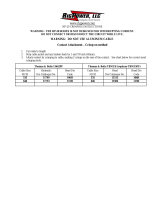
Lug and Crimping Information for Scotchlok Copper/Aluminum Lugs
40016 thru 40079
One hole
40132 thru 40178
Two hole
CRIMPING TOOL-DIE SETS (NUMBER OF CRIMPS)
Cable
Size
AWG/
kcmil
Stud
Size
(in.)
Scotch-
lok
Lug
Num-
b
Burndy Corporation Thomas & Betts Corporation
Square D Co. An-
derson Div.
ITT
Black-
burn Co.
Kearny
Nat’l
Div.
kcmil
ber
MD6 MY29 Y34A
Y35, Y39,
Y45*, Y46*
Y1000* TBM 5 TBM 8 TBM 12 TBM 15
VC6–3**
VC6–FT**
VC8C** OD58 TYPE O
6 5/16 40016 W161(1) 6AWG(1) A6CAB(1) U6CABT(1) (1) Grey(1) Grey(1) — 29(1) (1) — BY19(3) J(3)
4 5/16 40020 W162(3) 4AWG(1) A4CAB(1) U4CABT(1) (1) Green(2) Green(2) — 37(1) (1) — BY53(3) P(3)
2
3/8
1/2
40024
40025
W163(3)
W163(3)
2AWG(1)
2AWG(1)
A2CAB(1)
A2CAB(1)
U2CABT(1)
U2CABT(1)
(1)
(1)
Pink(2)
Pink(2)
Pink(2)
Pink(2)
—
42H(2)
42H(2)
(1)
(1)
—
BY23(3)
BY23(3)
1/2(3)
1/2(3)
1
3/8
1/2
40028
40029
W163(3)
W163(3)
1AWG(1)
1AWG(1)
A1CAR(1)
A1CAR(1)
U1CART(1)
U1CART(1)
(1)
(1)
Gold(2)
Gold(2)
Gold(2)
Gold(2)
—
45(1)
45(1)
(1)
(1)
—
BY23(3)
BY23(3)
1/2(3)
1/2(3)
1/0
3/8
1/2
3/8
40032
40033
40132
W241(3)
W241(3)
W241(3)
1/0(1)
1/0(1)
1/0(1)
A25AR(1)
A25AR(1)
A25AR(1)
U25ART(1)
U25ART(1)
U25ART(1)
(1)
(1)
(1)
Tan(2)
Tan(2)
Tan(2)
Tan(2)
Tan(2)
Tan(2)
—
50(1)
50(1)
50(1)
(1)
(1)
(1)
—
BY25(3)
BY25(3)
BY25(3)
5/8–1(3)
5/8–1(3)
5/8–1(3)
2/0
1/2
1/2
40037
40137
BG(4)
BG(4)
2/0(1)
2/0(1)
A26AR(2)
A26AR(2)
U26ART(2)
U26ART(2)
(1)
(1)
Olive(2)
Olive(2)
Olive(2)
Olive(2)
—
54H(2)
54H(2)
(2)
(2)
—
BY31C(3)
BY31C(3)
5/8–1(3)
5/8–1(3)
3/0
1/2
1/2
40041
40141
W166(4)
W166(4)
3/0(1)
3/0(1)
A27AR(2)
A27AR(2)
U27ART(2)
U27ART(2)
(1)
(1)
Ruby(2)
Ruby(2)
Ruby(2)
Ruby(2)
—
60(2)
60(2)
(2)
(2)
— —
737(3)
737(3)
4/0
1/2
5/8
1/2
40045
40046
40145
W660(4)
W660(4)
W660(4)
4/0 (2)
4/0 (2)
4/0 (2)
A28AR(2)
A28AR(2)
A28AR(2)
U28ART(2)
U28ART(2)
U28ART(2)
(1)
(1)
(1)
—
White(4)
White(4)
White(4)
—
66(4)
66(4)
66(4)
(2)
(2)
(2)
—
BY35C(4)
BY35C(4)
BY35C(4)
840(4)
840(4)
840(4)
250
1/2
5/8
1/2
40049
40050
40149
W249(3)
W249(3)
W249(3)
—
A29AR(2)
A29AR(2)
A29AR(2)
U29ART(2)
U29ART(2)
U29ART(2)
(1)
(1)
(1)
— —
71H(4)
71H(4)
71H(4)
71H(2)
71H(2)
71H(2)
(3)
(3)
(3)
— — —
300
1/2
1/2
40053
40153
— —
A30AR(2)
A30AR(2)
U30ART(2)
U30ART(2)
(1)
(1)
— —
76H(4)
76H(4)
76H(2)
76H(2)
(3)
(3)
— — —
350
1/2
5/8
1/2
40056
40057
40156
— — —
U31ART(2)
U31ART(2)
U31ART(2)
(1)
(1)
(1)
— —
87H(4)
87H(4)
87H(4)
87H(3)
87H(3)
87H(3)
(3)
(3)
(3)
— — —
400 1/2 40160 — — — U32ART(4) (1) — — 94H(4) 94H(4) — (2) — —
500
5/8
1/2
40067
40166
— — —
U34ART(4)
U34ART(4)
(1)
(1)
— —
106H(4)
106H(4)
106H(3)
106H(3)
—
(2)
(2)
— —
600 1/2 40170 — — — U36ART(4) (1) — — — 115H(3) — (3) — —
750
5/8
1/2
40073
40172
— — —
U39ART(4)
U39ART(4)
(1)
(1)
— — —
125H(5)
125H(5)
—
(3)
(3)
— —
1000
5/8
1/2
40079
40178
— — —
S44ART(4)
S44ART(4)
(1)
(1)
— — —
140H(4)
140H(4)
—
(3)
(3)
— —
* Y45 and Y46 accept all Y35 dies (“U” series). For Y45 use PT6515 adapter. For Y46 use PUADP adapter.
** Anderson VC6–3, VC6–FT, VC8C and Burndy Y1000 require no die set.

— 9 —
Tooling Index
Lug and Crimping Information for Scotchlok Copper Lugs
30014 thru 30045
One hole
31036 thru 31068
One hole — long barrel
31145 thru 31178
Two hole
CRIMPING TOOL-DIE SETS (NUMBER OF CRIMPS)
Cable
Size
AWG/
kil
Stud
Size
(in.)
Scotchlok
Copper Lug
Number
Burndy Corporation Thomas & Betts Corporation
Square D Co. An-
derson Div.
kcmil
(in
.
)
N
u
mber
MD6 MY29 Y34A
Y35, Y39, Y45*,
Y46*
TBM 5 TBM 8 TBM 15 VC6–3, VC6–FT**
6
10
1/4
5/16
30014
30015
30016
— 6AWG(1) — U5CRT(1) Blue(1) Blue(1) — Universal(1)
4
10
1/4
3/8
30018
30019
30021
W161(1) 4AWG(1) A4CR(1) U4CRT(1) Grey(1) Grey(1) — Universal(1)
2
1/4
5/16
3/8
30022
30023
30024
W162(2) 2AWG(1) A2CR(1) U2CRT(2) Brown(1) Brown(1) 33(1) Universal(2)
1
5/16
3/8
30027
30028
— 1AWG(1) A1CR(1) U1CRT(2) Green(1) Green(1) 37(1) Universal(2)
1/0
5/16
3/8
30031
30032
W163(2) 1/0(1) A25R(1) U25RT(1) Pink(2) Pink(2) 42H(2) Universal(1)
2/0
3/8
3/8
30036
31036
W241(2)
W241(3)
2/0(1)
2/0(2)
A26R(1)
A26R(2)
U26RT(2)
U26RT(3)
Black(2)
Black(3)
Black(2)
Black(3)
45(1)
45(2)
Universal(1)
Universal(2)
3/0
1/2
1/2
30041
31041
W243(2)
W243(3)
3/0(1)
3/0(2)
A27R(1)
A27R(2)
U27RT(2)
U27RT(3)
Orange(2)
Orange(3)
Orange(2)
Orange(3)
50(1)
50(2)
Universal(2)
Universal(3)
4/0
1/2
1/2
1/2
30045
31045
31145
BG(3)
BG(4)
BG(4)
4/0(1)
4/0(2)
4/0(2)
A28R(2)
U28RT(2)
U28RT(3)
U28RT(3)
Purple(2)
Purple(3)
Purple(3)
Purple(2)
Purple(3)
Purple(3)
54H(2)
54H(3)
54H(3)
Universal(2)
Universal(3)
Universal(3)
250
1/2
1/2
31049
31149
W166(4) 250(2) A29R(2) U29RT(3) Yellow(2) Yellow(2) 62(2) Universal(2)
300
1/2
1/2
31053
31153
— — A30R(2) U30RT(3) — White(3) 66(3) Universal(3)
350
1/2
1/2
31056
31156
— — A31R(2) U31RT(3) — Red(4) 71H(4) —
400
1/2
1/2
31060
31160
— — A32R(2) U32RT(3) — Blue(4) 76H(4) —
500
1/2
5/8
1/2
31066
31067
31166
— — A34R(2) U34RT(3) — Brown(4) 87H(4) —
600
1/2
1/2
31068
31168
— — — U36RT(3) — Green(4) 94H(4) —
750 1/2 31172 — — —
Y39, Y45, Y46
U39RT(5)
— — 106H(4) —
1000 1/2 31178 — — —
Y45: S44RT(6)
Y46: P44RT(6)
— — 125H(4) —
* Y45 and Y46 accept all Y35 dies (“U” series). For Y45 use PT6515 adapter. For Y46 use PUADP adapter.
** Anderson VC6–3, VC6–FT, VC8C and Burndy Y1000 require no die se

`3M', `Cold Shrink', `Scotch' and `Scotchlok' are trademarks of 3M.
UniShield
is a registered trademark of BICC Cables.
6801 River Place Blvd.
Austin, TX 78726-9000
Electrical Products Division
Important Notice to Purchaser:
All statements, technical information and recommendations related to the Seller's products are based on information believed to be reliable,
but the accuracy or completeness thereof is not guaranteed. Before utilizing the product, the user should determine the suitability of the product
for its intended use. The user assumes all risks and liability whatsoever in connection with such use.
Any statements or recommendations of the Seller which are not contained in the Seller's current publications shall have no force or effect unless
contained in an agreement signed by an authorized officer of the Seller. The statements contained herein are made in lieu of all warranties
expressed or implied, including but not limited to the implied warranties of merchantability and fitness for a particular purpose which warranties
are hereby expressly disclaimed.
SELLER SHALL NOT BE LIABLE TO THE USER OR ANY OTHER PERSON UNDER ANY LEGAL THEORY, INCLUDING BUT NOT LIMITED TO
NEGLIGENCE OR STRICT LIABILITY, FOR ANY INJURY OR FOR ANY DIRECT OR CONSEQUENTIAL DAMAGES SUSTAINED OR INCURRED
BY REASON OF THE USE OF ANY OF THE SELLER'S PRODUCTS.
Recycled paper
40% pre-consumer
10% post-consumer
Litho in USA
1997 3M
78-8114-1266-3 (B)
Tooling Index
Crimping Information for
3M Stem Connectors
Copper/Aluminum
CRIMPING TABLE FOR 3M STEM TYPE CONNECTOR
Conductor
S
3M Connector Num-
Recommended Crimping Tools
Size ber
Manufacturer Mech. Tool Die (No. Crimps) Hydraulic Die (No. Crimps)
Burndy MD6 BG(4), W243(4) Y35, Y39, Y45** U25ART(2), U243(2)
2 Solid
12
SC0020
SC0001
Kearny 0–51, 0–52 5/8–1 (4) 12, 20, 40, Ton 5/8–1(4)
1
,
2
1/0
SC0001
SC0010
T & B TBM 8 Olive(2) TBM 15 50(2)*
Anderson — — VC6 Universal(2)
Burndy MD6 W669(0) 840(5)* Y35, Y39, Y45** U28ART(2)
2/0
3/0
SC0020
SC0030
Kearny 0–51, 0–52 840(5)* WH–1, WH–2 840(2)
3/0
4/0
SC0030
SC0040
T & B TBM 8 White(4) TBM 15 66(3)
Anderson - — VC6 Universal(2)
* Y45 and Y46 accept all Y35 dies (“U” series). For Y45 use PT6515 adapter. For Y46 use PUADP adapter.
** Anderson VC6–3, VC6–FT, VC8C and Burndy Y1000 require no die set.
/