Print offsets 0, 0.3
Page 2Page 1
AR-B5430 User's Manual
AR-B5430 CPU Board
AR-B5430 CPU BoardAR-B5430 CPU Board
AR-B5430 CPU Board
EPIC form factor, onboard VGA, LVDS with DDR2-SODIMM
EPIC form factor, onboard VGA, LVDS with DDR2-SODIMMEPIC form factor, onboard VGA, LVDS with DDR2-SODIMM
EPIC form factor, onboard VGA, LVDS with DDR2-SODIMM
Built in two
Built in twoBuilt in two
Built in two LAN, CF type-II
LAN, CF type-II LAN, CF type-II
LAN, CF type-II
AR-B5430 User's Manual
Edition: 1.00
Book Number: AR-B5430-08.06.09
c Copyright 2006
All Rights Reserved.
Manual’s first edition: October 31, 2006
For the purpose of improving reliability, design and function, the information in this document is subject to
change without prior notice, which does not represent a commitment on the part of the manufacturer.
In no event will the manufacturer be liable for direct, indirect, special, incidental, or consequential damages
arising out of the use or inability to use the product or documentation, even if advised of the possibility of
such damages.
This document contains proprietary information protected by copyright. All rights are reserved. No part of this
Manual may be reproduced by any mechanical, electronic, or other means in any form without prior written
permission of the manufacturer.

Page 4Page 3
AR-B5430 User's Manual AR-B5430 User's Manual
Contents
ContentsContents
Contents
INTRODUCTION
INTRODUCTIONINTRODUCTION
INTRODUCTION
1
11
1
1.1 SPECIFICATIONS
4
44
4
4
1.2 WHAT YOU HAVE
1.3 BLOCK DIAGRAM
5
6
INSTALLATION
INSTALLATIONINSTALLATION
INSTALLATION
2
22
2
7
77
7
2.1 LOCATIONS
2.2 LIST OF CONNECTORS AND JUMPER SETTINGS
7
8
3
33
3
BIOS SETTING
BIOS SETTINGBIOS SETTING
BIOS SETTING
3.1 MAIN SETUP
3.2 ADVANCED CHIPSET SETUP
3.3 PNP/PCI SETUP
3.4 PERIPHERALS SETUP
3.5 PC HEALTH SETUP
3.6 BOOT SETUP
3.7 EXIT SETUP
11
12
13
14
15
16
17
10
1010
10
INTRODUCTION
INTRODUCTIONINTRODUCTION
INTRODUCTION
1
11
1
Welcome to the AR-B5430 EPIC board. The AR-B5430 incorporates the advanced Intel 945GM Chipset.
It supports the uFC-PGA 478 Core 2 Duo/Core Duo/Core Solo and Celeron M processors.
1.1 SPECIFICATIONS
1.1 SPECIFICATIONS1.1 SPECIFICATIONS
1.1 SPECIFICATIONS
CPU:
CPU:CPU:
CPU:
Socket for uFC-PGA 478 Core 2 Duo/Core Duo/Core
Solo/Celeron M, Coolers required.
while coming with a 400/533MHz Front Side Bus.
R
BIOS:
BIOS:BIOS:
BIOS:
AWARD BIOS
Chipset:
Chipset:Chipset:
Chipset:
945GM + ICH7M
Memory:
Memory:Memory:
Memory:
One SO-DIMM socket support 667/533 MHz DDR2
SDRAM up to 2GB
Graphic:
Graphic:Graphic:
Graphic:
945GM integrated GMA 950 graphic controller
VGA Memory: Intel DVMT 3.0 supports Max 224 MB
shared video memory Dual Display
Audio:
Audio:Audio:
Audio:
5.1 CH Audio Realtek ALC655 AC'97
Ethernet:
Ethernet:Ethernet:
Ethernet:
2 x Broadcom BCM5787 (10/100/1000Mbps)
1 x SATA, 1 x PATA, 1 x CF (Compact
Flash Type-II)
Storage:
Storage:Storage:
Storage:
Serial:
Serial:Serial:
Serial:
RS232 (COM1,COM3,COM4), RS232/422/485(COM2)
USB:
USB:USB:
USB:
2 x external ports, 2 x internal ports
PCI-104:
PCI-104:PCI-104:
PCI-104:
1 x PCI-104 (PCI Interface)
PS/2:
PS/2:PS/2:
PS/2:
One PS/2 connector for keyboard and mouse
GPIO:
GPIO:GPIO:
GPIO:
8 bit GPIO
Watch dog:
Watch dog:Watch dog:
Watch dog:
Software programmable
Hardware monitor:
Hardware monitor:Hardware monitor:
Hardware monitor:
CPU voltage & CPU/System temperature
Dimension:
Dimension:Dimension:
Dimension:
Lihium Battery, 3V/220mAH
Operating Temperature:
Operating Temperature:Operating Temperature:
Operating Temperature:
0~60oC (32~140oF)
Storage Temperature:
Storage Temperature:Storage Temperature:
Storage Temperature:
-20~80oC (-4~176oF)
Battery:
Battery:Battery:
Battery:
115mm x 165mm (4.528 x 6.496 inches)
4
44
4
Quick Manual
Quick ManualQuick Manual
Quick Manual 19
1919
19

Page 6Page 5
AR-B5430 User's Manual AR-B5430 User's Manual
1.2 What You Have
1.2 What You Have1.2 What You Have
1.2 What You Have
Before you begin to install your AR-B5430 board, please make sure that the following items are
inside the AR-B5430 package.
The quick manual
AR-B5430 board
Software utility CD
Fan module
Power cable for ATX
COM port cable
KB/MS cable
40/44 pin IDE connector
USB cable
Audio cable
SATA cable
DVI cable
x1
x1
x1
x1
x1
x1
x1
x1
x1
x2
x1
x1
TV out cable x1
1.3 Block Diagram
1.3 Block Diagram1.3 Block Diagram
1.3 Block Diagram

Page 8Page 7
AR-B5430 User's Manual AR-B5430 User's Manual
INSTALLATION
INSTALLATIONINSTALLATION
INSTALLATION
2
22
2
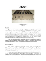
and the layout of AR-B5430. It then describes the unpacking information which you should be
This chapter describes the installation of AR-B5430. At first, it shows the Function diagram
careful with, as well as the jumper/switch settings for the AR-B5430 configuration.
2.1 Locations
2.1 Locations2.1 Locations
2.1 Locations
CON6
FAN2
JP2
AUDIO1FAN1
J9
JP1
IR1
COM4 COM3 COM2
GPIO1
DVI3
VGA1CON1
TVCON1
LAN1 LAN2 USB1 KM1
J7
J6
JBAT1
IDE1
BAT1
CON2
J8 (PCI104)
USB2
LCD1
SATA1
J5
LCDPW1
J1
PWR2
2.2
2.22.2
2.2 List of Connectors and Jumper Settings
List of Connectors and Jumper Settings List of Connectors and Jumper Settings
List of Connectors and Jumper Settings
LCDPW1:
Backlight Power (Output)
COM2:
Serial Port 2
COM3:
Serial Port 3
COM4:
Serial Port 4
USB2:
USB Port 3,2
1
1
2
2
1
2
9
10
10
9
1 6
D2+
GND
GND
D3+
9
D3-
2
GND
1
GND
10
+5V
D2-
R-IN
A-GND
SL-OUT
1
L-IN
LFT-OUT
R-OUT
A-GND
AUDIO1:
Audio Port
L-OUT
13
A-GND
A-GND
MIC-IN
14
SR-OUT
A-GND
SEN-OUT
2
+12V
GND
GND
BLCT
BLEN
+12V
GND
DTR2
TX2
RX2
DCD2 DSR2
RTS2
CTS2
RI2
NC
DSR3
RTS3
CTS3
RI3
GND
DTR3
TX3
RX3
DCD3
RI3
RTS3
CTS3
NC
DSR3
RX3
TX3
DCD3
DTR3
GND
NC
+5V
9
10
CBVS
REV.
NC
1
NC
NC
S-Y
GND
REV.
13
S-Pr
GND
GND
14
GND
REV.
NC
2
TVCON1:
TV-Output Port
PWR2:
Power +12V (Input)
12
34
+12V
+12V
GND
GND
BUZ-
71
8
RESET
J9:
PWR.SW, Reset, Buzzer
BUZ+
GND
GND POSW
2
3
1
CON6:
ATX Power SB5V Input
GND
5VSB
PSON
+12V
4
1
+3.3V
GND
+5V
CON2:
SATA1 Power (Output)
RX-
4
TX+
1
TX-
J5:
RS422/485 Port
RX+
Share with COM2
GPIO1:
Digtal I/O
1
2
9
10
FAN1:
System Fan
FAN2:
CPU Fan
GND
+5V
DIO0
DIO1
DIO2
DIO3
DIO7
DIO6
DIO5
DIO4
BAT1:
Battery Input
GND
+5V
D2
+5V
D10
GND
43
A2
DMA66
NC
GND
IRQ
D3
A0
IDE1
D14
RST
D1
GND
GND
GND
CS1
DACK
D5
D11
IRDY
IOW
D6
NC
D4
NC
D12
D9
A1
IOR
D0
CS3
D15
D8
DREQ
44
2
CSEL
D13
D7
1
ACT
GND
GND
2
GND
1
3VIN
3
1
FAN+
DET.
GND
DET.
1
GND
3
+12V
LCD1:
LCD Output Port
TX0-
GND
VSYNC
DVI3:
Digital Visual Interface
1
HSYNC
BLUE
RED
GND
25
GND
I2CK
DAT
TX1+
+5V
TXC+
GREEN
HPD
GND TX2+
GND
GND
I2DT
26
TX0+
GND
TX1-
CLK
2
TX2-
TXC-
IR1:
IrDA Port
1 5
+5V
NC
GND
RX
TX
E1-
ECK-
O0-
NC
O1-
ECK+
GND
O2-
2
I2DAT
E1+
GND
I2CLK
+VDD
OCK+
1
NC
O0+
E2+
+VDD
NC
29
GND
E2-
OCK-
E0-
GND
E0+
GND
NC
O2+
30
+VDD
O1+

Page 9
AR-B5430 User's Manual AR-B5430 User's Manual
JP1
1
2
5
6
J1
1 3
JBAT1
1
3
J7
J6
2
1
1
JP2
2
2-3 Short, Reset CMOS
1-2 Short, Normal(Default)
(Default)
1-2 Short,
SERIRQ
to SL1
Pin B1
(Default)
1-2 Short, LCD Power=5.0V
1-2 Short, COM2=RS232
3-4 Short, COM2=RS422
5-6 Short, COM2=RS485
(Default) 2-3 Short, LCD Power=3.3V
1-2 Short, CF is Master(Default)
2-3 Short, CF is Slave
(Default) 1-2 Short, KEYBOARD Enabled
2
1
1-2 Open, KEYBOARD Disabled
LAN2
KM1
USB1
LAN1
CON1
Serial ATA Port1
VGA1
RJ45 LAN1
RJ45 LAN2
PS2 KB/MS
DSUB15 VGA Port
USB Port 0,1
DSUB-9 Serial Port1
SATA1
Page 10
BIOS SETTING
BIOS SETTINGBIOS SETTING
BIOS SETTING
3
33
3
This chapter describes the BIOS menu displays and explains how to perform common tasks needed
to get up and running. It also gives detailed explanation of the elements found in each of
the BIOS menus. The following topics are covered:
MAIN SETUP
MAIN SETUPMAIN SETUP
MAIN SETUP
ADVANCED CHIPSET SETUP
ADVANCED CHIPSET SETUPADVANCED CHIPSET SETUP
ADVANCED CHIPSET SETUP
PNP/PCI SETUP
PNP/PCI SETUPPNP/PCI SETUP
PNP/PCI SETUP
PERIPHERALS SETUP
PERIPHERALS SETUPPERIPHERALS SETUP
PERIPHERALS SETUP
PC HEALTH SETUP
PC HEALTH SETUPPC HEALTH SETUP
PC HEALTH SETUP
BOOT SETUP
BOOT SETUPBOOT SETUP
BOOT SETUP
EXIT SETUP
EXIT SETUPEXIT SETUP
EXIT SETUP

Page 11
AR-B5430 User's Manual AR-B5430 User's Manual
3.1 MAIN SETUP
3.1 MAIN SETUP3.1 MAIN SETUP
3.1 MAIN SETUP
Page 12
3.2 ADVANCED CHIPSET SETUP
3.2 ADVANCED CHIPSET SETUP3.2 ADVANCED CHIPSET SETUP
3.2 ADVANCED CHIPSET SETUP
Once you enter the AwardBIOS. CMOS Setup Utility, the Main Menu will appear on the screen.
Use the arrow keys to highlight the item and then use the <Pg Up> <Pg Dn> keys to select the
value you want in each item.
Note : Listed at the bottom of the menu are the control keys. If you need any help with the
item fields, you can press the <F1> key, and it will display the relevant information.

Page 13
AR-B5430 User's Manual AR-B5430 User's Manual
Page 14
3.3 PNP/PCI SETUP
3.3 PNP/PCI SETUP3.3 PNP/PCI SETUP
3.3 PNP/PCI SETUP 3.4 PERIPHERALS SETUP
3.4 PERIPHERALS SETUP3.4 PERIPHERALS SETUP
3.4 PERIPHERALS SETUP

AR-B5430 User's Manual AR-B5430 User's Manual
Page 15 Page 16
3.5 PC HEALTH SETUP
3.5 PC HEALTH SETUP3.5 PC HEALTH SETUP
3.5 PC HEALTH SETUP 3.6 BOOT SETUP
3.6 BOOT SETUP3.6 BOOT SETUP
3.6 BOOT SETUP
This section shows the parameters in determining the PC Health Status. These parameters include
temperatures, fan speeds, and voltages.

Page 17
AR-B5430 User's Manual AR-B5430 User's Manual
Page 18
3.7 EXIT SETUP
3.7 EXIT SETUP3.7 EXIT SETUP
3.7 EXIT SETUP

Page 1-1 AR-B5430 Quick Manual
PartNo:220010350-G
CON6
FAN2
JP2
AUDIO1FAN1
J9
JP1
IR1
COM4 COM3 COM2
GPIO1
DVI3
VGA1CON1
TVCON1
LAN1 LAN2 USB1 KM1
J7
J6
JBAT1
IDE1
BAT1
CON2
J8 (PCI104)
USB2
LCD1
SATA1
LCDPW1:
Backlight Power (Output)
LCD1:
LCD
Output
Port
COM2:
Serial Port 2
COM3:
Serial Port 3
COM4:
Serial Port 4
JP1
DVI3:
Digital Visual Interface
BAT1:
Battery Input
USB2:
USB Port 3,2
GPIO1:
Digtal I/O
1
1
1
1
1
2
2
2
2
2
1
2
9
10
10
9
9
10
25
1 2
1 6
5
6
J1
1 3
JBAT1
1
3
J7
J6
2
1
1
JP2
2
IDE1
2
4344
1
1
1
3
3
FAN1:
System Fan
FAN2:
CPU Fan
J5
AR-B5430
Quick Manual
D2+
GND
GND
D3+
9
D3-
2
GND
1
GND
10
+5V
D2-
R-IN
A-GND
SL-OUT
1
L-IN
LFT-OUT
R-OUT
A-GND
AUDIO1:
Audio Port
L-OUT
13
A-GND
A-GND
MIC-IN
14
SR-OUT
A-GND
SEN-OUT
2
+12V
GND
GND
BLCT
BLEN
+12V
GND
+5V
DIO0
DIO1
DIO2
DIO3
DIO7
DIO6
DIO5
DIO4
FAN+
DET.
GND
GND
DET.
+12V
GND
DTR2
TX2
RX2
DCD2 DSR2
RTS2
CTS2
RI2
NC
DSR3
RTS3
CTS3
RI3
GND
DTR3
TX3
RX3
DCD3
RI3
RTS3
CTS3
NC
DSR3
RX3
TX3
DCD3
DTR3
GND
GND
3VIN
TX0+
TX0-
TX1+ TX1-
TX2+
TX2-
TXC+ TXC-
HPD
I2DT
I2CK
GND
GND
GND
GND
GND
GND
GND
+5V
RED
GREEN
BLUE
VSYNC
HSYNC
CLK
DAT
LAN2
KM1
USB1
LAN1
CON1
Serial ATA Port1
VGA1
NC
+5V
D7
D6
D5
D4
D3
D2
D1
D0
GND
DREQ
IOW
IOR
IRDY
DACK
IRQ
A1
A0
CS1
ACT
+5V
GND
RSTGND
D8
D9
D10
D11
D12
D13
D14
D15
NC
GND
GND
GND
CSEL
GND
NC
DMA66
A2
CS3
GND
+5V
NC
26
30
1
29
2
I2CLK
OCK-
GND
NC
E2+
ECK-
O2+
O0+
+VDD
+VDD
GND
E1-
NC
E0+
O1-
GND
GND
NC
ECK+
E2-
I2DAT
NC
O1+
O2-
E1+
E0-
GND
O0-
OCK+
+VDD
2-3 Short, Reset CMOS
1-2 Short, Normal(Default)
(Default)
1-2 Short,
SERIRQ to SL1 Pin B1
(Default)
1-2 Short, LCD Power=5.0V
1-2 Short, COM2=RS232
3-4 Short, COM2=RS422
5-6 Short, COM2=RS485
(Default) 2-3 Short, LCD Power=3.3V
1-2 Short, CF is Master(Default)
2-3 Short, CF is Slave
(Default) 1-2 Short, KEYBOARD Enabled
RJ45 LAN1
RJ45 LAN2
PS2 KB/MS
DSUB15 VGA Port
USB Port 0,1
DSUB-9 Serial Port1
SATA1
Print offsets 0, 0.3
9
10
2
1
LCDPW1
J1
PWR2
CBVS
REV.
NC
1
NC
NC
S-Y
GND
REV.
13
S-Pr
GND
GND
14
GND
REV.
NC
2
TVCON1:
TV-Output Port
1-2 Open, KEYBOARD Disabled
IR1:
IrDA Port
1 5
+5V
NC
GND
RX
TX
PWR2:
Power +12V (Input)
12
34
+12V
+12V
GND
GND
BUZ-
71
8
RESET
J9:
PWR.SW, Reset, Buzzer
BUZ+
GND
GND POSW
2
3
1
CON6:
ATX Power SB5V Input
GND
5VSB
PSON
+12V
4
1
+3.3V
GND
+5V
CON2:
SATA1 Power (Output)
RX-
4
TX+
1
TX-
J5:
RS422/485 Port
RX+
Share with COM2
/