Page is loading ...

Quick Reference Guide
RP-4
Control Processor
The RP-4 Control Processor is a powerful central controller that is designed for reliable control of audio/
video and other electronic systems. It combines an integrated 433MHz RF receiver, four assignable IR ports,
relays, support for the RTiPanel App (ver 1.2 or higher) and more — all in a small, cost-effective package.
The RP-4 is the perfect control processor for single room installations such as home theaters, media centers,
and bedrooms.
The RP-4 provides superior quality and reliability as well as these features:
• Stores all system commands and macros for reliable control.
• Integrated 433MHz RF receiver.
• Four infrared ports with routing and output adjustment.
• Supports RTiPanel App for one-way control via smart phones and tablets.
• Two voltage sense inputs for reliable, predictable control of devices.
• Two programmable relay outputs.
• Works with all RTI 433MHz wireless interfaces.
• RF signal reception LED.
• USB and Ethernet programming.

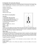
Touchscreen Control Panel
Connection Options
Model RP-4
Remote Control Processor
ETHERNET PORT 1 PORT 2 PORT 3 PORT 4
Sense Inputs: +3-24VDC
Relays: +30VDC, 5A max
IR OUTPUT LEVEL
POWER USB
RESET
STATUS NETLINK RF LINK
POWER / SENSE RELAYS
+12VDC
GROUND
SENSE IN 1
SENSE IN 2
CONTACT A
CONTACT B
CONTACT A
CONTACT B
IR Output Adjustment Controls
USB
Power
Supply
+12VDC
Relays (2)
Status Lights
Reset Button
Antenna
MOUNTING INSTRUCTIONS
The RP-4 should be located on a secure, at surface, or mounted to a wall, shelf, or
cabinet using the enclosed mounting bracket.
IMPORTANT NOTE: When mounting the RP-4, be certain to choose a safe location
(e.g. away from electrical wires, junction boxes, wet locations, etc.)
MOUNTING BRACKET INSTALLATION:
DRYWALL
1. Level the RP-4 mounting bracket in the desired location on the wall and mark the
fastener holes with a pencil.
2. Using a 3/16” (5mm) sized drill bit, drill holes through the drywall in marked
locations.
3. Insert the drywall anchors (included) into the holes and tap until they are ush
with wall.
4. Align mounting bracket with drywall anchors and screw (using supplied #6-32
screws) bracket to wall.
NON-DRYWALL (EX. Wood Panelling)
1. Level the RP-4 mounting bracket in the desired location and mark the fastener
holes with a pencil.
2. Pre-drill holes into surface in marked locations. (NOTE: The drill bit size will need
to be adjusted depending upon the screw and wall material used).
3. Align mounting bracket with holes and screw bracket to the wall using athead
screws.
MOUNTING RP-4 ON BRACKET
1. Aligning the RP-4 channel locks (located on the backside of the RP-4) over the
mounting bracket channel lock clips (located on the front of the mounting plate).
2. Slide the RP-4 down until the channel lock clips lock into place.
Amplied IR Connecting Block
More than two emitters per port
requires an amplied IR connecting
block.
Direct to IR Port
Single or Dual
IR Emitters
IR Output Options
Ethernet Network (LAN)
Sense Inputs (2)
Ground
RTI Remote Control
RP-4 Mounting Bracket
Channel Lock
Clips (4)
Fastener Holes (4)

It’s Under Control
®
INSTALLATION NOTES:
The RP-4 does not support any RTI wired interfaces (In-wall touchpanels, keypads, etc).
It is not possible to add additional RM-433 433MHz RF antennas and ZM-24 Zigbee transceivers.
The RP-4 supports one-way control via the RTiPanel App (NOTE: Virtual Panel is NOT supported).
If an RTiPanel device is in the Integration Designer system le, the computer used to download to the RP-4 must have an Internet connection.
INSTALLING THE ANTENNA
Insert the antenna on to the RP-4 BNC connector and twist the collar clockwise until it locks into place.
POWERING THE RP-4
The included AC adapter should be connected to the POWER jack on the RP-4 or the 12VDC/Ground terminals (see below). The power LED will turn-on.
NOTE: Use only the supplied AC adapter (12VDC Power Supply) to power the RP-4.
CONNECTIONS
CONNECTING IR EMITTERS
The four (4) IR emitter ports on the RP-4 are compatible with industry standard infrared emitters and connecting blocks. Each output port is capable of driving up to two
infrared emitters directly. More than two infrared emitters per port requires an amplied connecting block. A connecting block can be wired up to 1000 feet away from the
RP-4 using #22 AWG (minimum) wire.
ADJUSTING IR OUTPUT GAIN
The IR output gain can be separately adjusted for each of the four output ports. The RP-4 is shipped with the IR gain set to the optimum level for most equipment, and
it should only need to be adjusted if the attached equipment is not responding reliably. If adjustment is needed, rotate the IR output controls on the front of the RP-4
clockwise for higher output power, or counter-clockwise for lower output power.
VOLTAGE SENSE
The RP-4 has two voltage sense inputs (+3-24 VDC) that are congurable within Integration Designer. Based on the status
of the voltage sense input, macros can be programmed to trigger IR commands, RS-232 commands, relay closure, etc.
Connect the positive lead from voltage source to the RP-4 Sense In 1 or 2 terminal.
Connect the negative lead from the voltage source to the RP-4 Ground terminal.
RELAYS
The two relays in the RP-4 can provide contact closure or switching control for loads up to 5A/30VDC each. Both relays are
Normally Open when not energized, but they can be programmed to behave Normally Closed as long as power is applied
to the RP-4. The RP-4 relays can also be used as voltage (12VDC) triggers which requires additional wiring (see below).
For equipment that requires a momentary trigger, a macro will need to be created which closes the relay, has a
short time delay (.2-.5 second), then opens the relay.
For Contact Closure Control:
1. Connect the Contact A and B terminals of an RP-4 relay to the equipment being controlled.
For Voltage Trigger (12VDC) Control:
1. Connect the Ground terminal of the RP-4 to the ground connection on the equipment to be triggered.
2. Install a jumper wire (#22 AWG) between the +12VDC and Contact A terminal of the relay being
used on the RP-4.
3. Connect the Contact B terminal of a relay to the 12VDC power input on the equipment being triggered.
ETHERNET
This RJ-45 port allows connection to a 10/100 Base-T Ethernet network (LAN) for programming updates and one-way control with RTiPanel devices. Network settings such as
the IP address are congurable within Integration Designer.
NOTE: The RP-4 does not support control of devices via IP.
USB PORT
A standard USB B port (the type found on most printers) is used to download the Integration Designer programming software or rmware updates into the RP-4.
PROGRAMMING & OPERATION
PROGRAMMING THE RP-4
The RP-4 must be programmed to operate. All programming is done using RTI’s Integration Designer software and is downloaded using the USB port or over Ethernet. The
software allows you to create actions (e.g. commands and macros) that are associated with button presses on RTI wireless interfaces or RTiPanel devices. The software
automatically creates all of the system trigger codes, and generates the correct download for every device in the system.
NOTE: It is recommended that the rmware is updated on the RP-4 to the latest version. Check for the latest rmware version on the dealer section of the RTI website.
NOTE: If an RTiPanel device is in the Integration Designer system le, the computer used to download to the RP-4 must have an Internet connection.
THE STATUS LED
The status LED will illuminate red and stay red if there is no Integration Designer system le installed on the RP-4.
The status LED will illuminate green while the RP-4 rmware is being updated. Once the rmware is nished updating, the status LED will shut off.
The status LED will illuminate green while the RP-4 is loading the Integration Designer system le that is installed. Once nished loading, the status LED will shut off.
NOTE: If an RTiPanel device is in the Integration Designer system le, the status light will remain off while the RTiPanel les are being uploaded (this may take a little while).
The status LED will ash red while the RP-4 is powering up. Once the RP-4 is booted up, the LED will shut off (assuming a system le is loaded).
The status LED will illuminate green if a valid system trigger code is detected. The LED will stay on while the RP-4 is busy processing the action associated with the trigger
code.
NET LINK LED
The Net Link LED will illuminate if the RP-4 is connected to an Ethernet network. The LED will ash intermittently dependent upon trafc.
RF LINK LED
The RF Link LED blinks green when the RP-4 receives an transmission at 433MHz from an RTI remote control.
The RF Link LED blinks red when the RP-4 receives an transmission at 433MHz from an unrecognized device.
SETTING THE ZONE CODE
If the RP-4 is installed in close proximity to other RTI control systems using 433MHz RF, the system Zone Code can be changed in the Integration Designer software. This
allows up to 256 separate control systems to operate in the same general area, such as multi-dwelling units or homes with more than one media system.
Installation & Operation
Fastener Holes (4)
Model RP-4
Remote Control Processor
ETHERNET PORT 1 PORT 2 PORT 3 PORT 4
Sense Inputs: +3-24VDC
Relays: +30VDC, 5A max
IR OUTPUT LEVEL
POWER USB
RESET
STATUS NETLINK RF LINK
POWER / SENSE RELAYS
+12VDC
GROUND
SENSE IN 1
SENSE IN 2
CONTACT A
CONTACT B
CONTACT A
CONTACT B
+12VDC Voltage Trigger Wiring
Model RP-4
Remote Control Processor
ETHERNET PORT 1 PORT 2 PORT 3 PORT 4
Sense Inputs: +3-24VDC
Relays: +30VDC, 5A max
IR OUTPUT LEVEL
POWER USB
RESET
STATUS NETLINK RF LINK
POWER / SENSE RELAYS
+12VDC
GROUND
SENSE IN 1
SENSE IN 2
CONTACT A
CONTACT B
CONTACT A
CONTACT B
Contact Closure Wiring
To equipment ground
To equipment +12VDC input
Model RP-4
Remote Control Processor
ETHERNET PORT 1 PORT 2 PORT 3 PORT 4
Sense Inputs: +3-24VDC
Relays: +30VDC, 5A max
IR OUTPUT LEVEL
POWER USB
RESET
STATUS NETLINK RF LINK
POWER / SENSE RELAYS
+12VDC
GROUND
SENSE IN 1
SENSE IN 2
CONTACT A
CONTACT B
CONTACT A
CONTACT B
To equipment ground
To equipment +12VDC output
Voltage Sense Wiring
To equipment being controlled

It’s Under Control
®
If you are encountering any problems or have a question about your RTI product, please contact RTI
Technical Support for assistance (see the Contacting RTI section of this guide for contact details).
RTI provides technical support by telephone, fax or e-mail. For the highest quality service, please have
the following information ready, or provide it in your fax or e-mail.
• Your Name
• Company Name
• Telephone Number
• E-mail Address
• Product model and serial number (if applicable)
If you are having a problem with hardware, please note the equipment in your system, a description of
the problem, and any troubleshooting you have already tried.
Please do not return products to RTI without a return authorization.
Service & Support
For news about the latest updates, new product information,
and new accessories, please visit our web site at:
www.rticorp.com
For general information, you can contact RTI at:
Remote Technologies Incorporated
5775 12th Ave. E Suite 180
Shakopee, MN 55379
Tel. (952) 253-3100
Fax (952) 253-3131
Contacting RTI
Safety Suggestions
Federal Communications Commission Notice
This equipment has been tested and found to comply with the limits for a Class B digital device, pursuant to Part 15 of the FCC Rules. These limits are designed to provide
reasonable protection against harmful interference in a residential installation. Any changes or modications not expressly approved by the party responsible for compliance
could void the user’s authority to operate the device.
This equipment generates, uses, and can radiate radio frequency energy and, if not installed and used in accordance with the instructions, may cause harmful interference to
radio communications. However, there is no guarantee that interference will not occur in a particular installation.
If this equipment does cause harmful interference to radio or television reception, which can be determined by turning the equipment off and on, the user is encouraged to try
to correct the interference by one or more of the following measures:
Reorient or relocate the receiving antenna.
Increase the separation between the equipment and the receiver.
Connect the equipment into an outlet on a circuit different from that to which the receiver is connected.
Consult the dealer or an experienced radio/TV technician for help.
This device complies with Part 15 of the FCC Rules. Operation is subject to the following two conditions:
1. This device may not cause harmful interference.
2. This device must accept any interference received including interference that may cause undesired operation.
Read and Follow Instructions. Read all safety and operating instructions before operating the unit.
Retain Instructions. Keep the safety and operating instructions for future reference.
Heed Warnings. Adhere to all warnings on the unit and in the operating instructions.
Heat. Keep the unit away from heat sources such as radiators, heat registers, stoves, etc., including ampliers that produce heat.
Power Sources. Connect the unit only to a power supply of the type described in the operating instructions, or as marked on the unit.
Power Cord Protection. Route power supply cords so that they are not likely to be walked on or pinched by items placed on or against them, paying particular attention to the
cord plugs at power receptacles and at the point at which they exit from the unit.
Water and Moisture. Do not use the unit near water—for example, near a sink, in a wet basement, near a swimming pool, near an open window, etc.
Object and Liquid Entry. Do not allow objects to fall or liquids to be spilled into the enclosure through openings.
Servicing. Do not attempt any service beyond that described in the operating instructions. Refer all other service needs to qualied service personnel.
Damage Requiring Service. The unit should be serviced by qualied service personnel when:
The power supply cord or the plug has been damaged.
Objects have fallen or liquid has been spilled into the unit.
The unit has been exposed to rain.
The unit does not appear to operate normally or exhibits a marked change in performance.
The unit has been dropped or the enclosure has been damaged.
N27917
Limited Warranty
RTI warrants its products for a period of one (1) year (90 days only for included battery packs); or for a period of time compliant with local laws when applicable from the date
of purchase from RTI or an authorized RTI distributor.
This warranty may be enforced by the original purchaser and subsequent owners during the warranty period, so long as the original dated sales receipt or other proof of
warranty coverage is presented when warranty service is required.
Except as specied below, this warranty covers all defects in material and workmanship in this product. The following are not covered by the warranty:
Damage resulting from:
1. Accident, misuse, abuse, or neglect.
2. Failure to follow instructions contained in this Guide.
3. Repair or attempted repair by anyone other than Remote Technologies Incorporated.
4. Failure to perform recommended periodic maintenance.
5. Causes other than product defects, including lack of skill, competence or experience of user.
6. Shipment of this product (claims must be made to the carrier).
7. Being altered or which the serial number has been defaced, modied or removed.
DECLARATION OF CONFORMITY (DOC)
The Declaration of Conformity for this product can be found on the RTI website at: www.rticorp.com/declaration
Copyright © 2014 • Remote Technologies Incorporated • All rights reserved. 70-210138-22 V1.0
• One (1) RP-4 Control Processor
• One (1) 433MHz RF Antenna
• One (1) International power supply kit
• One (1) Mounting bracket
• Four (4) Screws (#6-32) and drywall anchors
• One (1) Quick reference guide
• One (1) Firmware update notication
Product Contents
/