Page is loading ...

LN-25
™
PRO WIRE FEEDER
,/&
April, 2011
For use with machines having Code Numbers:
,+/"&'.%
• Sales and Service through Subsidiaries and Distributors Worldwide •
Cleveland, Ohio 44117-1199 U.S.A. TEL: 216.481.8100 FAX: 216.486.1751 WEB SITE: www.lincolnelectric.com
• World's Leader in Welding and Cutting Products •
Copyright © Lincoln Global Inc.
Safety Depends on You
Lincoln arc welding and cutting
equipment is designed and built
with safety in mind. However,
your overall safety can be
increased by proper installation
... and thoughtful operation on
your part. DO NOT INSTALL,
OPERATE OR REPAIR THIS
EQUIPMENT WITHOUT
READING THIS MANUAL
AND THE SAFETY PRE-
CAUTIONS CONTAINED
THROUGHOUT. And, most
importantly, think before you act
and be careful.
Return to Master TOC Return to Master TOC Return to Master TOC Return to Master TOC
View Safety Info View Safety Info View Safety Info View Safety Info
RETURN TO MAIN MENU

%'S)+(
,-2
< <
(+' "'
CBJ8E878DH<C@8AG
1.a. Turn the engine off before troubleshooting and maintenance
work unless the maintenance work requires it to be running.
____________________________________________________
1.b.Operate engines in open, well-ventilated
areas or vent the engine exhaust fumes
outdoors.
____________________________________________________
1.c. Do not add the fuel near an open flame weld-
ing arc or when the engine is running. Stop
the engine and allow it to cool before refuel-
ing to prevent spilled fuel from vaporizing on
contact with hot engine parts and igniting. Do
not spill fuel when filling tank. If fuel is spilled,
wipe it up and do not start engine until fumes
have been eliminated.
____________________________________________________
1.d. Keep all equipment safety guards, covers and devices in posi-
tion and in good repair.Keep hands, hair, clothing and tools
away from V-belts, gears, fans and all other moving parts
when starting, operating or repairing equipment.
____________________________________________________
1.e. In some cases it may be necessary to remove safety
guards to perform required maintenance. Remove
guards only when necessary and replace them when the
maintenance requiring their removal is complete.
Always use the greatest care when working near moving
parts.
___________________________________________________
1.f. Do not put your hands near the engine fan.
Do not attempt to override the governor or
idler by pushing on the throttle control rods
while the engine is running.
___________________________________________________
1.g. To prevent accidentally starting gasoline engines while
turning the engine or welding generator during maintenance
work, disconnect the spark plug wires, distributor cap or
magneto wire as appropriate.
+0%"' 64A58;4M4E7BHF)+(--2(.+,%'(-!+,+(&)(,,"%,+"(.,"'#.+2(+-!
$)!"%+'02)&$+0++,,!(.%(',.%-0"-!-!"+(-(+(+()+-"'
Read and understand the following safety highlights. For additional safety information, it is strongly recommended that you
purchase a copy of “Safety in Welding & Cutting - ANSI Standard Z49.1” from the American Welding Society, P.O. Box 351040,
Miami, Florida 33135 or CSA Standard W117.2-1974. A Free copy of “Arc Welding Safety” booklet E205 is available from the
Lincoln Electric Company, 22801 St. Clair Avenue, Cleveland, Ohio 44117-1199.
,.+ -!- %% "',-%%-"(' ()+-"(' &"'-'' ' +)"+ )+(.+, +
)+(+&('%22*.%"""'"/".%,
0+'"'
%-+"'
& '-""%,
@4L5874A:8EBHF
2.a. Electric current flowing through any conductor causes
localized Electric and Magnetic Fields (EMF). Welding
current creates EMF fields around welding cables and
welding machines
2.b. EMF fields may interfere with some pacemakers, and
welders having a pacemaker should consult their physician
before welding.
2.c. Exposure to EMF fields in welding may have other health
effects which are now not known.
2.d. All welders should use the following procedures in order to
minimize exposure to EMF fields from the welding circuit:
2.d.1.
Route the electrode and work cables together - Secure
them with tape when possible.
2.d.2. Never coil the electrode lead around your body.
2.d.3. Do not place your body between the electrode and
work cables. If the electrode cable is on your right
side, the work cable should also be on your right side.
2.d.4. Connect the work cable to the workpiece as close as
possible to the area being welded.
2.d.5. Do not work next to welding power source.
1.h. To avoid scalding, do not remove the
radiator pressure cap when the engine is
hot.
%"(+'")+()(,"-"('0+'"' ,
Diesel engine exhaust and some of its constituents
are known to the State of California to cause can-
cer, birth defects, and other reproductive harm.
The engine exhaust from this product contains
chemicals known to the State of California to cause
cancer, birth defects, or other reproductive harm.
The Above For Diesel Engines
The Above For Gasoline Engines
Return to Master TOC Return to Master TOC Return to Master TOC Return to Master TOC

,-2
<< <<
%'S)+(
.&,' ,,
64A5874A:8EBHF
5.a. Welding may produce fumes and gases
hazardous to health. Avoid breathing these
fumes and gases.When welding, keep
your head out of the fume. Use enough
ventilation and/or exhaust at the arc to keep
fumes and gases away from the breathing zone. 0;8A
J8?7<A: J<G; 8?86GEB78F J;<6; E8DH<E8 FC86<4?
I8AG<?4G<BA FH6; 4F FG4<A?8FF BE ;4E7 946<A: F88
<AFGEH6G<BAF BA 6BAG4<A8E BE &,, BE BA ?847 BE
647@<H@ C?4G87 FG88? 4A7 BG;8E @8G4?F BE 6B4G<A:F
J;<6; CEB7H68 ;<:;?L GBK<6 9H@8F >88C 8KCBFHE8 4F
?BJ 4F CBFF<5?8 4A7 J<G;<A 4CC?<645?8 (,! )% 4A7
"!-%/?<@<GFHF<A:?B64?8K;4HFGBE@86;4A<64?I8A
G<?4G<BA "A 6BA9<A87 FC468F BE <A FB@8 6<E6H@FG4A68F
BHG7BBEF 4 E8FC<E4GBE @4L 58 E8DH<E8777<G<BA4? CE8
64HG<BAF4E84?FB E8DH<E87J;8AJ8?7<A:BA:4?I4A<M87
FG88?
5. b. The operation of welding fume control equipment is affected
by various factors including proper use and positioning of the
equipment, maintenance of the equipment and the specific
welding procedure and application involved. Worker expo-
sure level should be checked upon installation and periodi-
cally thereafter to be certain it is within applicable OSHA PEL
and ACGIH TLV limits.
5.c.
Do not weld in locations near chlorinated hydrocarbon
vapors
coming from degreasing, cleaning or spraying operations.
The heat and rays of the arc can react with solvent vapors
to
form phosgene, a highly toxic gas, and other irritating prod-
ucts.
5.d. Shielding gases used for arc welding can displace air and
cause injury or death. Always use enough ventilation,
especially in confined areas, to insure breathing air is safe.
5.e. Read and understand the manufacturer’s instructions for this
equipment and the consumables to be used, including the
material safety data sheet (MSDS) and follow your
employer’s safety practices. MSDS forms are available from
your welding distributor or from the manufacturer.
5.f. Also see item 1.b.
++2,64A5HEA
4.a. Use a shield with the proper filter and cover
plates to protect your eyes from sparks and
the rays of the arc when welding or observing
open arc welding. Headshield and filter lens
should conform to ANSI Z87. I standards.
4.b. Use suitable clothing made from durable flame-resistant
material to protect your skin and that of your helpers from
the arc rays.
4.c. Protect other nearby personnel with suitable, non-flammable
screening and/or warn them not to watch the arc nor expose
themselves to the arc rays or to hot spatter or metal.
%-+",!($64A><??
3.a. The electrode and work (or ground) circuits
are electrically “hot” when the welder is on.
Do not touch these “hot” parts with your bare
skin or wet clothing. Wear dry, hole-free
gloves to insulate hands.
3.b. Insulate yourself from work and ground using dry insulation.
Make certain the insulation is large enough to cover your full
area of physical contact with work and ground.
"A477<G<BAGBG;8ABE@4?F498GLCE864HG<BAF<9J8?7<A:
@HFG 58 C8E9BE@87 HA78E 8?86GE<64??L ;4M4E7BHF
6BA7<G<BAF <A 74@C ?B64G<BAF BE J;<?8 J84E<A: J8G
6?BG;<A:BA@8G4?FGEH6GHE8FFH6;4F9?BBEF:E4G<A:FBE
F6499B?7F J;8A <A 6E4@C87 CBF<G<BAF FH6; 4F F<GG<A:
>A88?<A:BE?L<A:<9G;8E8<F4;<:;E<F>B9HA4IB<745?8BE
466<78AG4? 6BAG46G J<G; G;8 JBE>C<868 BE :EBHA7 HF8
G;89B??BJ<A:8DH<C@8AG
R,8@<4HGB@4G<6BAFG4AG/B?G4:80<E808?78E
R&4AH4?,G<6>08?78E
R08?78EJ<G;+87H687/B?G4:8BAGEB?
3.c. In semiautomatic or automatic wire welding, the electrode,
electrode reel, welding head, nozzle or semiautomatic
welding gun are also electrically “hot”.
3.d. Always be sure the work cable makes a good electrical
connection with the metal being welded. The connection
should be as close as possible to the area being welded.
3.e. Ground the work or metal to be welded to a good electrical
(earth) ground.
3.f.
Maintain the electrode holder, work clamp, welding cable and
welding machine in good, safe operating condition. Replace
damaged insulation.
3.g. Never dip the electrode in water for cooling.
3.h. Never simultaneously touch electrically “hot” parts of
electrode holders connected to two welders because voltage
between the two can be the total of the open circuit voltage
of both welders.
3.i. When working above floor level, use a safety belt to protect
yourself from a fall should you get a shock.
3.j. Also see Items 6.c. and 8.
Return to Master TOC Return to Master TOC Return to Master TOC Return to Master TOC

%'S)+(
,-2
<<< <<<
(+%-+"%%2
CBJ8E878DH<C@8AG
8.a. Turn off input power using the disconnect
switch at the fuse box before working on
the equipment.
8.b. Install equipment in accordance with the U.S. National
Electrical Code, all local codes and the manufacturer’s
recommendations.
8.c. Ground the equipment in accordance with the U.S. National
Electrical Code and the manufacturer’s recommendations.
2%"'+@4L8KC?B78
<974@4:87
7.a. Use only compressed gas cylinders
containing the correct shielding gas for the
process used and properly operating
regulators designed for the gas and
pressure used. All hoses, fittings, etc. should be suitable for
the application and maintained in good condition.
7.b. Always keep cylinders in an upright position securely
chained to an undercarriage or fixed support.
7.c. Cylinders should be located:
• Away from areas where they may be struck or subjected to
physical damage.
• A safe distance from arc welding or cutting operations and
any other source of heat, sparks, or flame.
7.d. Never allow the electrode, electrode holder or any other
electrically “hot” parts to touch a cylinder.
7.e. Keep your head and face away from the cylinder valve outlet
when opening the cylinder valve.
7.f. Valve protection caps should always be in place and hand
tight except when the cylinder is in use or connected for
use.
7.g. Read and follow the instructions on compressed gas
cylinders, associated equipment, and CGA publication P-l,
“Precautions for Safe Handling of Compressed Gases in
Cylinders,” available from the Compressed Gas Association
1235 Jefferson Davis Highway, Arlington, VA 22202.
0%"' 4A7 .--"'
,)+$,64A64HF89<E8BE
8KC?BF<BA
6.a.
Remove fire hazards from the welding area.
If
this is not possible, cover them to prevent the welding sparks
from starting a fire. Remember that welding sparks and hot
materials from welding can easily go through small cracks
and openings to adjcent areas. Avoid welding near hydraulic
lines. Have a fire extinguisher readily available.
6.b. Where compressed gases are to be used at the job site,
special precautions should be used to prevent hazardous
situations. Refer to “Safety in Welding and Cutting” (ANSI
Standard Z49.1) and the operating information for the
equipment being used.
6.c. When not welding, make certain no part of the electrode
circuit is touching the work or ground. Accidental contact can
cause overheating and create a fire hazard.
6.d. Do not heat, cut or weld tanks, drums or containers until the
proper steps have been taken to insure that such procedures
will not cause flammable or toxic vapors from substances
inside. They can cause an explosion even
though
they have
been “cleaned”. For information, purchase “Recommended
Safe Practices for the
Preparation
for Welding and Cutting of
Containers and Piping That Have Held Hazardous
Substances”, AWS F4.1 from the American Welding Society
(see address above).
6.e. Vent hollow castings or containers before heating, cutting or
welding. They may explode.
6.f.
Sparks and spatter are thrown from the welding arc. Wear oil
free protective garments such as leather gloves, heavy shirt,
cuffless trousers, high shoes and a cap over your hair. Wear
ear plugs when welding out of position or in confined places.
Always wear safety glasses with side shields when in a
welding area.
6.g. Connect the work cable to the work as close to the welding
area as practical. Work cables connected to the building
framework or other locations away from the welding area
increase the possibility of the welding current passing through
lifting chains, crane cables or other alternate circuits. This can
create fire hazards or overheat lifting chains or cables until
they fail.
6.h. Also see item 1.c.
6.I. Read and follow NFPA 51B “ Standard for Fire Prevention
During Welding, Cutting and Other Hot Work”, available from
NFPA 1 Batterymarch Park,PO box 9101, Quincy, Ma
022690-9101.
6.j. Do not use a welding power source for pipe thawing.
Refer to ;GGCJJJ?<A6B?A8?86GE<66B@F498GL for additional safety information.
Return to Master TOC Return to Master TOC Return to Master TOC Return to Master TOC

,-2
<I <I
%'S)+(
)+N.-"(',,Y+-N
Pour votre propre protection lire et observer toutes les instructions
et les précautions de sûreté specifiques qui parraissent dans ce
manuel aussi bien que les précautions de sûreté générales suiv-
antes:
,PE8GO)BHE,BH74:8%[E6
1. Protegez-vous contre la secousse électrique:
a. Les circuits à l’électrode et à la piéce sont sous tension
quand la machine à souder est en marche. Eviter toujours
tout contact entre les parties sous tension et la peau nue
ou les vétements mouillés. Porter des gants secs et sans
trous pour isoler les mains.
b. Faire trés attention de bien s’isoler de la masse quand on
soude dans des endroits humides, ou sur un plancher met-
allique ou des grilles metalliques, principalement dans
les positions assis ou couché pour lesquelles une grande
partie du corps peut être en contact avec la masse.
c. Maintenir le porte-électrode, la pince de masse, le câble de
soudage et la machine à souder en bon et sûr état defonc-
tionnement.
d.Ne jamais plonger le porte-électrode dans l’eau pour le
refroidir.
e. Ne jamais toucher simultanément les parties sous tension
des porte-électrodes connectés à deux machines à souder
parce que la tension entre les deux pinces peut être le total
de la tension à vide des deux machines.
f. Si on utilise la machine à souder comme une source de
courant pour soudage semi-automatique, ces precautions
pour le porte-électrode s’applicuent aussi au pistolet de
soudage.
2. Dans le cas de travail au dessus du niveau du sol, se protéger
contre les chutes dans le cas ou on recoit un choc. Ne jamais
enrouler le câble-électrode autour de n’importe quelle partie du
corps.
3. Un coup d’arc peut être plus sévère qu’un coup de soliel, donc:
a. Utiliser un bon masque avec un verre filtrant approprié ainsi
qu’un verre blanc afin de se protéger les yeux du rayon-
nement de l’arc et des projections quand on soude ou
quand on regarde l’arc.
b. Porter des vêtements convenables afin de protéger la peau
de soudeur et des aides contre le rayonnement de l‘arc.
c. Protéger l’autre personnel travaillant à proximité au
soudage à l’aide d’écrans appropriés et non-inflammables.
4. Des gouttes de laitier en fusion sont émises de l’arc de
soudage. Se protéger avec des vêtements de protection libres
de l’huile, tels que les gants en cuir, chemise épaisse, pan-
talons sans revers, et chaussures montantes.
5. Toujours porter des lunettes de sécurité dans la zone de
soudage. Utiliser des lunettes avec écrans lateraux dans les
zones où l’on pique le laitier.
6. Eloigner les matériaux inflammables ou les recouvrir afin de
prévenir tout risque d’incendie dû aux étincelles.
7. Quand on ne soude pas, poser la pince à une endroit isolé de
la masse. Un court-circuit accidental peut provoquer un
échauffement et un risque d’incendie.
8. S’assurer que la masse est connectée le plus prés possible de
la zone de travail qu’il est pratique de le faire. Si on place la
masse sur la charpente de la construction ou d’autres endroits
éloignés de la zone de travail, on augmente le risque de voir
passer le courant de soudage par les chaines de levage,
câbles de grue, ou autres circuits. Cela peut provoquer des
risques d’incendie ou d’echauffement des chaines et des
câbles jusqu’à ce qu’ils se rompent.
9. Assurer une ventilation suffisante dans la zone de soudage.
Ceci est particuliérement important pour le soudage de tôles
galvanisées plombées, ou cadmiées ou tout autre métal qui
produit des fumeés toxiques.
10. Ne pas souder en présence de vapeurs de chlore provenant
d’opérations de dégraissage, nettoyage ou pistolage. La
chaleur ou les rayons de l’arc peuvent réagir avec les vapeurs
du solvant pour produire du phosgéne (gas fortement toxique)
ou autres produits irritants.
11. Pour obtenir de plus amples renseignements sur la sûreté, voir
le code “Code for safety in welding and cutting” CSA Standard
W 117.2-1974.
)+N.-"(',,Y+-N)(.+
%,&!"',U,(.+U
-+',(+&-.+-U
++,,.+
1. Relier à la terre le chassis du poste conformement au code de
l’électricité et aux recommendations du fabricant. Le dispositif
de montage ou la piece à souder doit être branché à une
bonne mise à la terre.
2. Autant que possible, I’installation et l’entretien du poste seront
effectués par un électricien qualifié.
3. Avant de faires des travaux à l’interieur de poste, la debranch-
er à l’interrupteur à la boite de fusibles.
4. Garder tous les couvercles et dispositifs de sûreté à leur place.
Return to Master TOC Return to Master TOC Return to Master TOC Return to Master TOC

" "
&,-+-%(('-'-,(+%%,-"(',
%'S)+(
Page
,498GL <<I
"AFG4??4G<BA . . . . . . . . . . . . . . . . . . . . . . . . . . . . . . . . . . . . . . . . . . . . . . . . . . . . . . . . . . . . . . . . . .,86G<BA
(C8E4G<BA . . . . . . . . . . . . . . . . . . . . . . . . . . . . . . . . . . . . . . . . . . . . . . . . . . . . . . . . . . . . . . . . . .,86G<BA
668FFBE<8F . . . . . . . . . . . . . . . . . . . . . . . . . . . . . . . . . . . . . . . . . . . . . . . . . . . . . . . . . . . . . . . .,86G<BA
&4<AG8A4A68 . . . . . . . . . . . . . . . . . . . . . . . . . . . . . . . . . . . . . . . . . . . . . . . . . . . . . . . . . . . . . . . .,86G<BA
-;8BELB9(C8E4G<BA . . . . . . . . . . . . . . . . . . . . . . . . . . . . . . . . . . . . . . . . . . . . . . . . . . . . . . . . . .,86G<BA
-EBH5?8F;BBG<A:4A7+8C4<E . . . . . . . . . . . . . . . . . . . . . . . . . . . . . . . . . . . . . . . . . . . . . . . . . . .,86G<BA
?86GE<64?<4:E4@F . . . . . . . . . . . . . . . . . . . . . . . . . . . . . . . . . . . . . . . . . . . . . . . . . . . . . . . . . .,86G<BA
)4EGF&4AH4? )
RETURN TO MAIN MENU

-%(('-'-,"',-%%-"(',-"('
%'S)+(
"AFG4??4G<BA
Technical Specifications . . . . . . . . . . . . . . . . . . . . . . . . . . . . . . . . . . . . . . . . . . . . . . . . . . . . . . . . . . . . . . . .A-2
Safety Precautions . . . . . . . . . . . . . . . . . . . . . . . . . . . . . . . . . . . . . . . . . . . . . . . . . . . . . . . . . . . . . . . . . . . .A-3
Location . . . . . . . . . . . . . . . . . . . . . . . . . . . . . . . . . . . . . . . . . . . . . . . . . . . . . . . . . . . . . . . . . . . . . . . . . . . .A-3
High Frequency Protection . . . . . . . . . . . . . . . . . . . . . . . . . . . . . . . . . . . . . . . . . . . . . . . . . . . . . . . . . . . . . .A-3
Weld Cable Size . . . . . . . . . . . . . . . . . . . . . . . . . . . . . . . . . . . . . . . . . . . . . . . . . . . . . . . . . . . . . . . . . . . . . .A-3
Cable Connections . . . . . . . . . . . . . . . . . . . . . . . . . . . . . . . . . . . . . . . . . . . . . . . . . . . . . . . . . . . . . . . . . . . .A-4
Shielding Gas Connections . . . . . . . . . . . . . . . . . . . . . . . . . . . . . . . . . . . . . . . . . . . . . . . . . . . . . . . . . . . . .A-4
Wire Drive Configuration . . . . . . . . . . . . . . . . . . . . . . . . . . . . . . . . . . . . . . . . . . . . . . . . . . . . . . . . . . . . . . .A-4
Changing The Gun Receiver Bushing . . . . . . . . . . . . . . . . . . . . . . . . . . . . . . . . . . . . . . . . . . . . . . . . . .A-4
Procedure To Install Drive Rolls and Wire Guides . . . . . . . . . . . . . . . . . . . . . . . . . . . . . . . . . . . . . . . .A-5
Pressure Arm Adjustment . . . . . . . . . . . . . . . . . . . . . . . . . . . . . . . . . . . . . . . . . . . . . . . . . . . . . . . . . . . . . . .A-6
Loading Spools of Wire . . . . . . . . . . . . . . . . . . . . . . . . . . . . . . . . . . . . . . . . . . . . . . . . . . . . . . . . . . . . . . . .A-6
Gun Connection . . . . . . . . . . . . . . . . . . . . . . . . . . . . . . . . . . . . . . . . . . . . . . . . . . . . . . . . . . . . . . . . . . . . . .A-6
Power Source to LN-25™ PRO Cable Connection Diagrams . . . . . . . . . . . . . . . . . . . . . . . . . . . . . . .A-7/A-8
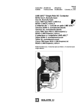
)+(.- '&
)+(.-
'.&+
(
'.&+,
LN-25™PRO
(NORMAL SPEED)
K2613-1
11387, 11507
11620, 11716
LN-25™PRO
(EXTRA TORQUE)
K2613-2
11388, 11508
11621, 11717
LN-25™PRO
(NORMAL SPEED)
K2613-5 11746
LN-25™PRO
(EXTRA TORQUE)
K2613-7 11747
&!"',(/+"'-!",&'.%
Return to Master TOC Return to Master TOC Return to Master TOC Return to Master TOC

"',-%%-"('
%'S)+(
-&)+-.++'
()+-"(' -40°F to 104°F (-40°C to 40°C)
,-(+ -40°F to 185°F (-40°C to 85°C)
"').-/(%- 4A7.++'-
-!'"%,)""-"(',V
%'S)+($4A7
!" !- 0"-! )-! 0" !-
14.8 Inches 8.7 Inches 22.2 Inches 36 lbs
(376 mm) (221 mm) (589 mm) (16 kg)
Handle folded down
)!2,"%"&',"(',
"').-/(%- T
15-110 VDC
(24-42 VAC with remote voltage control kit installed)
"').-&)+,
4A
+-(.-).-QQ
.-22%
60% rating
100% rating
"').-&)+,
450
325
+"' 0"+,)+' 0"+,"3
0,+'
50 – 400 ipm
(0.8 – 10.1m/min)
50 – 700 ipm
(1.3 – 17.7m/min)
0,+'
30 – 400 ipm
(0.8 – 10.1m/min)
50 – 700 ipm
(1.3 – 17.7m/min)
0"+,"3,
.023 – 1/16"
(0.6 – 1.6mm)
.023 – 1/16"
(0.6 – 1.6mm)
0"+,"3,
.030 - 3/32”
(10.3 – 2.4mm)
.030 - 5/64
(0.8 - 2.0mm)
+"'
Extra torque
K2613-2 & K2613-7
Normal Speed
K2613-1 & K2613-5
GMAW
FCAW
Return to Section TOC Return to Section TOC Return to Section TOC Return to Section TOC
Return to Master TOC Return to Master TOC Return to Master TOC Return to Master TOC

"',-%%-"('
%'S)+(
0%%,"3
-45?8Located below are copper cable sizes rec-
ommended for various currents and duty cycles.
Lengths stipulated are the distance from the welder to
work and back to the welder again. Cable sizes are
increased for greater lengths primarily for the purpose
of minimizing voltage drop in the cables.
** Tabled values are for operation at ambient temperatures of 104°F(40°C) and below. Applications above 104°F(40°C) may require cables
larger than recommended, or cables rated higher than 167°F(75°C).
+(&&'%,"3,+.+(/+())++-QBEQ
CABLE SIZES FOR COMBINED LENGTHS OF ELECTRODE AND WORK CABLES
AMPERES
200
200
225
225
250
250
250
250
300
325
350
400
400
500
PERCENT
DUTY
CYCLE
60
100
20
40 & 30
30
40
60
100
60
100
60
60
100
60
GBG
GB@
2
2
4 or 5
3
3
2
1
1
1
2/0
1/0
2/0
3/0
2/0
GBG
GB@
2
2
3
3
3
2
1
1
1
2/0
1/0
2/0
3/0
2/0
GBG
GB@
2
2
2
2
2
1
1
1
1
2/0
2/0
2/0
3/0
3/0
GBG
GB@
1
1
1
1
1
1
1
1
1/0
2/0
2/0
3/0
3/0
3/0
GBG
GB@
1/0
1/0
1/0
1/0
1/0
1/0
1/0
1/0
2/0
3/0
3/0
4/0
4/0
4/0
-%
,-2)+.-"(',
%-+"Z,!($'$"%%
R-HEAG;8<ACHGCBJ8E(4GG;8
7<F6BAA86GFJ<G6;BE9HF85BK
589BE84GG8@CG<A:GB6BAA86GBE
7<F6BAA86G<ACHGCBJ8E?<A8FBHG
CHG645?8FBE6BAGEB?645?8F
R(A?LDH4?<9<87C8EFBAA8?F;BH?7
C8E9BE@G;<F<AFG4??4G<BA
RBABGGBH6;@8G4?CBEG<BAFB9G;8%'S)+(
JBE>6?<CJ;8AG;8J8?7<A:CBJ8EFBHE68<FBA
RBABG4GG46;G;8JBE>6?<CGBG;8J<E898878E
RBAA86GG;8JBE>6?<C7<E86G?LGBG;8JBE>4F
6?BF84FCBFF<5?8GBG;8J8?7<A:4E6
R-HEACBJ8EB994GG;8J8?7<A:CBJ8EFBHE68
589BE87<F6BAA86G<A:G;8JBE>6?<C9EB@G;8
JBE>
R(A?LHF8BACBJ8EFBHE68FJ<G;BC8A6<E6H<G
IB?G4:8F?8FFG;4A/
%(-"('
For best wire feeding performance, place the LN-
25™ PRO on a stable and dry surface. Keep the
wire feeder in a vertical position. Do not operate the
wire feeder on an angled surface of more than 15
degrees.
Do not submerge the LN-25™ PRO.
The LN-25™ PRO is rated IP23 and is suitable for
outdoor use.
The handle of the LN-25™ PRO is intended for
moving the wire feeder about the work place only.
When suspending a wire feeder, insulate the
hanging device from the wire feeder enclosure.
!" !+*.'2)+(--"('
%B64G8G;8%'S)+(4J4L9EB@E47<B6BAGEB??87
@46;<A8EL -;8 ABE@4? BC8E4G<BA B9 G;8 %'S
)+(@4L47I8EF8?L49986GG;8BC8E4G<BAB9+6BA
GEB??878DH<C@8AGJ;<6;@4LE8FH?G<A5B7<?L<A=HEL
BE74@4:8GBG;88DH<C@8AG
0+'"'
.-"('
Return to Section TOC Return to Section TOC Return to Section TOC Return to Section TOC
Return to Master TOC Return to Master TOC Return to Master TOC Return to Master TOC

"',-%%-"('
%'S)+(
2. Remove the cylinder cap. Inspect the cylinder valves
and regulator for damaged threads, dirt, dust, oil or
grease. Remove dust and dirt with a clean cloth. (
'(- --! -! + .%-(+ " ("% +,
(+& ",)+,'-Inform your gas supplier
of this condition. Oil or grease in the presence of high
pressure oxygen is explosive
.
3. Stand to one side away from the outlet and open the
cylinder valve for an instant. This blows away any dust
or dirt which may have accumulated in the valve outlet.
4. Attach the flow regulator to the cylinder valve and tight-
en the union nut(s) securely with a wrench. Note: if
connecting to 100% CO
2
cylinder, insert regulator
adapter between regulator and cylinder valve. If
adapter is equipped with a plastic washer, be sure it is
seated for connection to the CO
2
cylinder.
5. Attach one end of the inlet hose to the outlet fitting of
the flow regulator. Attach the other end to the welding
system shielding gas inlet. Tighten the union nuts with
a wrench.
6. Before opening the cylinder valve, turn the regulator
adjusting knob counterclockwise until the adjusting
spring pressure is released.
7. Standing to one side, open the cylinder valve slowly a
fraction of a turn. When the cylinder pressure gage
stops moving, open the valve fully.
8. The flow regulator is adjustable. Adjust it to the flow
rate recommended for the procedure and process
being used before making a weld.
0"++"/('" .+-"('
(See Figure A.1)
!' "' -! .' +"/+
.,!"'
%-+",!($64A><??
R-HEAG;8<ACHGCBJ8E(4GG;8J8?7
<A:CBJ8E FBHE68 589BE8<AFG4??4G<BA
BE6;4A:<A:7E<I8EB??F4A7BE:H<78F
RBABGGBH6;8?86GE<64??L?<I8C4EGF
R0;8A<A6;<A:J<G;G;8:HAGE<::8E8?86GEB784A7
7E<I8@86;4A<F@4E8;BGGBJBE>4A7:EBHA7
4A7 6BH?7 E8@4<A 8A8E:<M87 F8I8E4? F86BA7F
49G8EG;8:HAGE<::8E<FE8?84F87
RB ABG BC8E4G8 J<G; 6BI8EF C4A8?F BE :H4E7F
E8@BI87BEBC8A
R(A?LDH4?<9<87C8EFBAA8?F;BH?7C8E9BE@@4<AG8
A4A68JBE>
)<A
A
B
C
D
E
0<E<A:
Trigger
Not used
Common
Not used
Not used
%(''-"(',
There is one circular connector for the gun trigger on
the front of the LN-25™ PRO.
HA6G<BA
5-pin trigger
connector for
push-guns
only.
A
E
C
B
D
-45?8
0+'"'
,!"%"' ,(''-"('
2%"'+ @4L 8KC?B78 <9
74@4:87
R $88C 6L?<A78E HCE<:;G 4A7
6;4<A87GBFHCCBEG
R$88C6L?<A78E4J4L9EB@4E84FJ;8E8<G@4L58
74@4:87
R'8I8E?<9GJ8?78EJ<G;6L?<A78E4GG46;87
R'8I8E4??BJJ8?7<A:8?86GEB78GBGBH6;6L?<A78E
R$88C6L?<A78E4J4L9EB@J8?7<A:BEBG;8E?<I8
8?86GE<64?6<E6H<GF
R."% .) ( ,!"%"' , &2
!+&!%-!(+$"%%
R,;HGB99F;<8?7<A::4FFHCC?LJ;8AABG<A
HF8
R,88 @8E<64A '4G<BA4? ,G4A74E7 3 ,498GL
<A 08?7<A: 4A7 HGG<A:X )H5?<F;87 5L G;8
@8E<64A08?7<A:,B6<8GL
Maximum inlet pressure is 100 psi. (6.9 bar.)
Install the shielding gas supply as follows:
1. Secure the cylinder to prevent it from falling.
0+'"'
Return to Section TOC Return to Section TOC Return to Section TOC Return to Section TOC
Return to Master TOC Return to Master TOC Return to Master TOC Return to Master TOC

"',-%%-"('
%'S)+(
Tools required:
• 1/4" hex key wrench.
1. Turn power off at the welding power source.
2. Remove the welding wire from the wire drive.
3. Remove the thumb screw from the wire drive.
4. Remove the welding gun from the wire drive.
5. Loosen the socket head cap screw that holds the
connector bar against the gun bushing.
"&)(+-'-
BABG4GG8@CGGB6B@C?8G8?LE8@BI8G;8FB6>8G
;84764CF6E8J
6. Remove the outer wire guide, and push the gun
bushing out of the wire drive. Because of the pre-
cision fit, light tapping may be required to remove
the gun bushing.
7. Disconnect the shielding gas hose from the gun
bushing, if required.
8. Connect the shielding gas hose to the new gun
bushing, if required.
9. Rotate the gun bushing until the thumb screw hole
aligns with the thumb screw hole in the feed plate.
Slide the gun receiver bushing into the wire drive
and verify the thumb screw holes are aligned.
10. Tighten the socket head cap screw.
11. Insert the welding gun into the gun bushing and
tighten the thumb screw.
'(-: Some gun bushings do not require the use of
the thumb screw.
GUN RECEIVER BUSHING
LOOSEN TIGHTEN
THUMB SCREW
OUTER WIRE GUIDE
SOCKET HEAD
CAP SCREW
CONNECTOR BLOCK
)+(.+ -("',-%% +"/ +(%%,
'0"+ .",
R -HEAG;8<ACHGCBJ8E(4GG;8J8?7
<A: CBJ8E FBHE68 589BE8 <AFG4??4G<BA
BE6;4A:<A:7E<I8EB??F4A7BE:H<78F
RBABGGBH6;8?86GE<64??L?<I8C4EGF
R0;8A<A6;<A:J<G;G;8:HAGE<::8E8?86GEB784A7
7E<I8@86;4A<F@4E8;BGGBJBE>4A7:EBHA7
4A7 6BH?7 E8@4<A 8A8E:<M87 F8I8E4? F86BA7F
49G8EG;8:HAGE<::8E<FE8?84F87
RB ABG BC8E4G8 J<G; 6BI8EF C4A8?F BE :H4E7F
E8@BI87BEBC8A
R(A?LDH4?<9<87C8EFBAA8?F;BH?7C8E9BE@@4<AG8
A4A68JBE>
------------------------------------------------------------------------
1. Turn power off at the welding power source.
2. Release the idle roll pressure arm.
3. Remove the outer wire guide by turning the knurled
thumbscrews counter-clockwise to unscrew them
from the feed plate. See <:HE8.
4. Rotate the triangular lock and remove the drive rolls.
5. Remove the inner wire guide
6. Insert the new inner wire guide, groove side out,
over the two locating pins in the feed plate.
7. Install a drive roll on each hub assembly secure with
the triangular lock.
8. Install the outer wire guide by aligning it with the pins
and tightening the knurled thumbscrews.
9. Close the idle arm and engage the idle roll pressure
arm. Adjust the pressure appropriately.
0+'"'
" .+
" .+
Return to Section TOC Return to Section TOC Return to Section TOC Return to Section TOC
Return to Master TOC Return to Master TOC Return to Master TOC Return to Master TOC

"',-%%-"('
%'S)+(
THUMB
SCREW
GUN
)+,,.++&#.,-&'-
%-+",!($64A><??
R-HEAG;8<ACHGCBJ8E(4GG;8J8?7
<A:CBJ8EFBHE68589BE8<AFG4??4G<BABE
6;4A:<A:7E<I8EB??F4A7BE:H<78F
RBABGGBH6;8?86GE<64??L?<I8C4EGF
R0;8A<A6;<A:J<G;G;8:HAGE<::8E8?86GEB784A7
7E<I8@86;4A<F@4E8;BGGBJBE>4A7:EBHA7
4A7 6BH?7 E8@4<A 8A8E:<M87 F8I8E4? F86BA7F
49G8EG;8:HAGE<::8E<FE8?84F87
RB ABG BC8E4G8 J<G; 6BI8EF C4A8?F BE :H4E7F
E8@BI87BEBC8A
R(A?LDH4?<9<87C8EFBAA8?F;BH?7C8E9BE@@4<AG8
A4A68JBE>
The pressure arm controls the amount of force the
drive rolls exert on the wire. Proper adjustment of the
pressure arm gives the best welding performance.
Set the pressure arm as follows:
(See <:HE8)
Aluminum wires between 1 and 3
Cored wires between 3 and 4
Steel, Stainless wires between 4 and 6
%("' ,)((%,(0"+
R$88C;4A7F;4<E6?BG;<A:4A7GBB?F
4J4L9EB@EBG4G<A:8DH<C@8AG
RBABGJ84E:?BI8FJ;8AG;E847<A:
J<E8BE6;4A:<A:J<E8FCBB?
R(A?LDH4?<9<87C8EFBAA8?F;BH?7<AFG4??
HF8BEF8EI<68G;<F8DH<C@8AG
Loading 10 to 15 lb. (4.5 – 6.8kg) Spools.
A K468 spindle adapter is required for loading 2"
(51mm) wide spools on 2" (51mm) spindles. Use a
K468 spindle adapter for loading 2-1/2" (64mm) wide
spools.
1. Squeeze the release bar on the retaining collar and
remove it from the spindle.
2. Place the spindle adapter on the spindle, aligning
the spindle brake pin with the hole in the adapter.
3. Place the spool on the spindle and align the adapter
brake tab with one of the holes in the back side of
the spool. An indicator mark on the end of the spin-
dle shows the orientation of the brake tab. Be cer-
tain the wire feeds off of the spool in the proper
direction.
4. Re-install the retaining collar. Make sure that the
release bar snaps out and that the retaining collar
fully engages the groove on the spindle.
.'(''-"('
%-+",!($64A><??
R-HEAG;8<ACHGCBJ8E(4GG;8J8?7
<A:CBJ8EFBHE68589BE8<AFG4??4G<BABE
6;4A:<A:7E<I8EB??F4A7BE:H<78F
RBABGGBH6;8?86GE<64??L?<I8C4EGF
R0;8A<A6;<A:J<G;G;8:HAGE<::8E8?86GEB784A7
7E<I8@86;4A<F@4E8;BGGBJBE>4A7:EBHA7
4A7 6BH?7 E8@4<A 8A8E:<M87 F8I8E4? F86BA7F
49G8EG;8:HAGE<::8E<FE8?84F87
RB ABG BC8E4G8 J<G; 6BI8EF C4A8?F BE :H4E7F
E8@BI87BEBC8A
R(A?LDH4?<9<87C8EFBAA8?F;BH?7C8E9BE@@4<AG8
A4A68JBE>
The LN-25™ PRO comes with a K1500-2 gun adapter
installed. (See <:HE8)
To install a gun,
1. Turn power OFF.
2. Remove the thumb screw.
3. Push the gun the completely into the gun bushing.
4. Secure the gun in place with the thumb screw.
5. Connect the trigger cable from the gun to the trigger
connector on the front of the feeder.
Note: Not all gun bushings require the use of the
thumb screw.
0+'"'
0+'"'
6
Al
Fe, CrNi
Fe, CrNi
ALUMINUM WIRES
CORED WIRES
STEEL, STAINLESS WIRES
" .+
0+'"'
" .+
Return to Section TOC Return to Section TOC Return to Section TOC Return to Section TOC
Return to Master TOC Return to Master TOC Return to Master TOC Return to Master TOC

"',-%%-"('
%'S)+(
+(,,-!+,-.),
)BJ8E,BHE68FJ<G;(HGCHG-8E@<A4?F?J4LF
!BG,88<:HE8
If the power source has a Remote/Local switch, place
the switch in the Local position.
Place the Power Source CC/CV switch (if present) or
Range Switch in the CV position if possible.
Set the CV/CC switch in the feeder to match the power
source.
/ )BJ8E ,BHE68F J<G; ,GH7 BAA86GBEF 4A7
+8@BG8%B64?,J<G6;,88<:HE8
Place the power source Remote/Local switch in the
Local position.
Place CV/CC switch in the feeder in the "CV" position.
LN-25 PRO
(Across the Arc)
CC Power Source
Ranger 250, 250 LPG
Ranger 305G, 305D
Commander 300
Vantage 300, 400, 500
Air Vantage 500
Ranger 10,000
Ranger 3 phase
SAE 400 with CV adapter
Engine Dri
ve
n welder with
Wire Feed Module
Work
Electrode
Work clip
LN-25 PRO
(Across the Arc)
Work
Electrode
Work clip
CV-655
CV-400
DC-400
DC-600
DC-655
V450-Pro
" .+
" .+
$
K2613-1
K2613-2
KP1695-XX
KP1696-XX
KP1697-XX
See Magnum Literature
K1803-1
8F6E<CG<BA
LN-25™ PRO Wire Feeder
LN-25™ PRO Extra Torque
Drive Roll Kit
Welding Gun
CC power Source
Welding Cables
)(0+,(.+-(%'S)+(
%(''-"('" +&,
$
K2613-1
K2613-2
KP1695-XX
KP1696-XX
KP1697-XX
See magnum Literature
K1803-1
8F6E<CG<BA
LN-25™ PRO Wire Feeder
LN-25™ PRO Extra Torque
Drive Roll Kit
Welding Gun
CV power Source
Welding Cables
Return to Section TOC Return to Section TOC Return to Section TOC Return to Section TOC
Return to Master TOC Return to Master TOC Return to Master TOC Return to Master TOC

"',-%%-"('
%'S)+(
/)BJ8E,BHE68J<G;-J<FG&4G8BAA86GBEF4A7
+8@BG8%B64?,J<G6;,88<:HE8
Place CV/CC switch in the feeder in the "CV" position.
LN-25 PRO
(Across the Arc)
V350-Pro
Work
Electrode
Work clip
" .+
$
K2613-1
K2613-2
KP1695-XX
KP1696-XX
KP1697-XX
See Magnum Literature
K1841
8F6E<CG<BA
LN-25™ PRO Wire Feeder
LN-25™ PRO Extra Torque
Drive Roll Kit
Welding Gun
CC power Source
Welding Cables
/)BJ8E,BHE68J<G;-J<FG&4G8BAA86GBEF4A7
AB+8@BG8%B64?,J<G6;,88<:HE8
Place CV/CC switch in the feeder in the "CV" position.
LN-25 PRO
(Across the Arc)
CV-250
CV-300
CV-305
Work
Electrode
Jumper
Work clip
" .+
$
K2613-1
K2613-2
KP1695-XX
KP1696-XX
KP1697-XX
See Magnum Literature
K1841-
K484
8F6E<CG<BA
LN-25™ PRO Wire Feeder
LN-25™ PRO Extra Torque
Drive Roll Kit
Welding Gun
CV power Source
Welding Cables
Jumper Plug kit
Return to Section TOC Return to Section TOC Return to Section TOC Return to Section TOC
Return to Master TOC Return to Master TOC Return to Master TOC Return to Master TOC

-%(('-'-,()+-"(',-"('
%'S)+(
(C8E4G<BA
Safety Precautions and Graphic Symbol Definitions . . . . . . . . . . . . . . . . . . . . . . . . . . . . . . . . . . . . . . . . . .B-2
General Description . . . . . . . . . . . . . . . . . . . . . . . . . . . . . . . . . . . . . . . . . . . . . . . . . . . . . . . . . . . . . . . . . . .B-3
Case Front Controls . . . . . . . . . . . . . . . . . . . . . . . . . . . . . . . . . . . . . . . . . . . . . . . . . . . . . . . . . . . . . .B-4 / B-8
CV Wire Feed Speed Operation . . . . . . . . . . . . . . . . . . . . . . . . . . . . . . . . . . . . . . . . . . . . . . . . . . . . . .B-4
CC Wire Feed Speed Operation . . . . . . . . . . . . . . . . . . . . . . . . . . . . . . . . . . . . . . . . . . . . . . . . . . . . .B-5
CV Wire Feed Speed Operation . . . . . . . . . . . . . . . . . . . . . . . . . . . . . . . . . . . . . . . . . . . . . . . . . . . . . .B-5
Constant Current vs Constant Voltage Wire Welding . . . . . . . . . . . . . . . . . . . . . . . . . . . . . . . . . . . . . .B-7
Internal Controls . . . . . . . . . . . . . . . . . . . . . . . . . . . . . . . . . . . . . . . . . . . . . . . . . . . . . . . . . . . . . . . . . . . . . .B-9
Description of Internal Controls . . . . . . . . . . . . . . . . . . . . . . . . . . . . . . . . . . . . . . . . . . . . . . . . . . . .B-10 / B-11
Rear Controls . . . . . . . . . . . . . . . . . . . . . . . . . . . . . . . . . . . . . . . . . . . . . . . . . . . . . . . . . . . . . . . . . . . . . . .B-12
Gas Purge/Flow Meter/Power-Up . . . . . . . . . . . . . . . . . . . . . . . . . . . . . . . . . . . . . . . . . . . . . . . . . . . . . . .B-13
Return to Master TOC Return to Master TOC Return to Master TOC Return to Master TOC

()+-"('
%'S)+(
R%-+" ,!($ ' $"%%
.A?8FF HF<A: (% 984
GHE8J;8A9887<A:J<G;:HAGE<:
:8E G;8 8?86GEB78 4A7 7E<I8
@86;4A<F@ 4E8 4?J4LF 8?86GE<
64??L 8A8E:<M87 4A7 6BH?7
E8@4<A 8A8E:<M87 F8I8E4? F86
BA7F49G8EG;8J8?7<A:684F8F
RB ABG GBH6; 8?86GE<64??L ?<I8 C4EGBE 8?86GEB78
J<G;F><ABEJ8G6?BG;<A:
R"AFH?4G8LBHEF8?99EB@JBE>4A7:EBHA7
R?J4LFJ84E7EL<AFH?4G<A::?BI8F
RB ABG BC8E4G8 J<G; 6BI8EF C4A8?F BE :H4E7F
E8@BI87BEBC8A
R.&, ' ,,, 64A 58
74A:8EBHF
R$88CLBHE;847BHGB99H@8F
R.F8 I8AG<?4G<BA BE 8K;4HFG GB
E8@BI8 9H@8F 9EB@ 5E84G;<A:
MBA8
R0%"' ,)+$, 64A 64HF8
9<E8BE8KC?BF<BA
R$88C9?4@@45?8@4G8E<4?4J4L
+Z+2,64A5HEA
R084E 8L8 84E 4A7 5B7L CEBG86
G<BA
, "-"('% 0+'"' "'(+&-"('
.'++ 0%"' ,-2)+.-"(',
'"'-! +('-(-!",()+-"' &'.
%
0+'"'
,-2)+.-"(',
+ ' .'+,-' '-"+ ,-"('
(+()+-"' &!"'
"').-)(0+
('
(
0"++
)(,"-"/(.-).-
' -"/(.-).-
"').-)(0+
"+-.++'-
()'"+."-
/(%-
"').-/(%-
(.-).-/(%-
"').-.++'-
(.-).-.++'-
)+(--"/
+(.'
0+'"' (+
.-"('
.
.
.
"
"
+)!" ,2&(%, -!- ))+ ('
-!",&!"'(+"'-!",&'.%
Return to Section TOC Return to Section TOC Return to Section TOC Return to Section TOC
Return to Master TOC Return to Master TOC Return to Master TOC Return to Master TOC

()+-"('
%'S)+(
"'"-"('(0%"' -+&,
0,
• Wire Feed Speed
RConstant Current
/
RConstant Voltage
&0
• Gas Metal Arc welding
,&0
RShielded Metal Arc welding
0
RFlux Core Arc Welding
'+%,+")-"('
8A8E4?);LF<64?8F6E<CG<BA
The LN-25™ PRO is specially engineered to be the
most rugged portable wire feeder available. The mod-
els covered by this manual are designed for “across
the arc” operation only.
Several models of the LN-25™ PRO are offered to
best meet individual welder needs. The Extra Torque
model features additional torque gearing for reliable
feeding of large diameter FCAW wires. The Standard
model features wire drive gearing for optimal perfor-
mance for both FCAW and GMAW wires of common
sizes. All of the models include a gas solenoid and
flow meter for the flexibility to run most wire processes.
The plastic case is molded from a high impact, flame
retardant plastic for durability and low weight. The
patent pending design keeps the internal components
protected and dry.
The heart of the LN-25™ PRO is the 2 roll MAX-
TRAC™ drive. The patented features on the wire drive
offer tool-less changing of the drive rolls and wire
guides for quick spool changes. A tachometer con-
trolled motor powers the patent pending drive rolls for
smooth, steady feeding without slippage.
With only one p.c. board, the LN-25™ PRO is
designed to be simple, reliable and easy to service.
The p.c. board is mounted with Lincoln’s leading envi-
ronmental design protection that consists of mounting
the board in a plastic tray and potting it with epoxy.
With a 325 amp 100% duty cycle rating, these feeders
are ready for heavy duty welding.
8A8E4?HA6G<BA4?8F6E<CG<BA
The LN-25™ PRO as designed is a simple, robust
feeder. Standard features include a calibrated wire
feed speed dial, 2 step/trigger interlock switch, CV-CC
switch, Gas Purge and Cold Feed. Some newer codes
also have a Wire Speed range switch for more precise
setting at lower speeds.
+(&&')+(,,,
• GMAW
• FCAW
)+(,,%"&"--"(',
• GMAW-P procedures must be qualified by the cus-
tomer.
• Across-the-Arc models are not recommended for
stitch or spot welding.
*.")&'-%"&"--"(',
• The duty cycle of the wire feeder is 325A, 100% and
450A, 60%. Duty cycle is based upon the amount of
welding performed in a 10 minute period.
• The maximum spool size is 45 lb, 12" diameter.
• Maximum FCAW gun length is 15 ft.
• Maximum GMAW gun length is 25 ft.
• Push-pull guns do not work with the wire feeder.
• K2330-1 Timer kits do not work with this feeder, use
K2330-2 kits
+(&&')(0+,(.+,
• CV-305
• CV-400
• CV-655
• DC-400
• DC-600
• DC-655
• Invertec V-350 PRO
• Invertec V-450 PRO
• Multi-Weld 350
• Ranger 10,000
• Ranger 3 Phase
• Ranger GXT
• Ranger 250
• Ranger 305
• SAE-400
• Pipeliner 200G
• Classic 300
• Vantage 300
• Vantage 400
• Vantage 500
Return to Section TOC Return to Section TOC Return to Section TOC Return to Section TOC
Return to Master TOC Return to Master TOC Return to Master TOC Return to Master TOC

()+-"('
%'S)+(
,+('-('-+(%, ,88<:HE8
'%( /(%-&-+
The analog voltmeter shows the voltage between
electrode and work. The voltmeter shows open cir-
cuit voltage when the wire feeder is not welding. As
a result, it is not unusual to see the needle “pegged”
when not welding. The voltmeter is polarity insensi-
tive and the range is 0 - 40VDC.
0"+,)$'(
The large, calibrated wire feed speed knob makes
for easy and accurate adjustment of the wire feed
speed. The knob rotates 3/4 turn. Turn the knob
clockwise to increase the wire feed speed, and
counter clockwise to reduce the wire feed speed.
Models with analog voltmeters have a calibrated
scale printed around the wire feed speed knob using
"in/min" units. A separate decal with "m/min" units is
included with these models wire feeder. Units with a
range switch have two calibrated scales.
0<E8887,C887/(C8E4G<BA
When Across the Arc models are operated with CV
power sources, the wire feed speed will remain a con-
stant value, independent of arc voltage changes, as
long as the arc voltage does not drop below the mini-
mum values per the following table.
-%/()+-"('
1
1
2
3
2
3
4
4
5
5
6
6
7
K2613-1 & K2613-2
K2613-5 & K2613-7
" .+
"-&
,+")-"('
1. Analog Voltmeter
2. Wire Feed Speed Control
3. 5-Pin Gun Trigger Receptacle
4. Work Sense Lead Connector
5 Thermal LED (Motor Overload)
6. Polarity LED
7. Wire Feed Speed Range Switch
&<A<@H@
E6/B?G4:8
&4K<@H@0,
,G4A74E7
&4K<@H@0,
KGE4-BEDH8
15 V 280”/min. 210”/min.
17V 340”/min. 235”/min.
21V 440”/min. 400”/min.
24V 520”/min. 400”/min.
27V 600”/min 400”/min.
Return to Section TOC Return to Section TOC Return to Section TOC Return to Section TOC
Return to Master TOC Return to Master TOC Return to Master TOC Return to Master TOC

()+-"('
%'S)+(
50
100
150
200
250
300
350
400
450
500
550
600
650
700
50 100 150 200 250 300 350 400 450 500 550
650 700
35
31
29
27
25
23
21
19
17
15
33
600
V
CC
" .+
0<E8887,C887(C8E4G<BA(,88<:HE8BE
See Table B.2
When Across the Arc models are operated with CC
power sources, the wire feed speed changes as the arc
voltage changes. When the arc voltage increases, the
wire feed speed will increase; and when the arc voltage
decreases, the wire feed speed will decrease.
To preset the wire feed speed on CC power sources:
1. Set the Wire Feed Mode switch inside the LN-25™
PRO to "CC".
2. Refer to the Figure B.2 graph for the setting for the
wire feed speed knob setting. Select the horizon-
tal line representing the Desired Wire Feed Speed.
(See Figure B.2 arrow for 375 in/min.)
3. Select the diagonal line representing the Arc Volts.
(See Figure B.2 for 29 volts.)
4. Determine the vertical line representing the CC
representing the CC Wire Feed Speed setting
where the above two lines cross. (See Figure B.2
arrow line for 450.) Set the LN-25™ PRO wire feed
speed knob to this value.
CC WFS dial setting = desired WFS x 35
Arc Volts
Example: 375 in/min. (Horizontal Line) x 35
29 Arc Volts (Diagonal Line)
= 13125 = 452-5 (Vertical Line)
29
Set the Wire Speed Control at 450”/min.,
and when welding at 29 volts the average
actual speed should be approximately
375“/min.
Return to Section TOC Return to Section TOC Return to Section TOC Return to Section TOC
Return to Master TOC Return to Master TOC Return to Master TOC Return to Master TOC

()+-"('
%'S)+(
-%//0"+,),--"'
109
131
153
175
197
97
117
136
156
175
88
105
123
140
158
80
95
111
127
143
73
88
102
117
131
67
81
94
108
121
63
75
88
100
113
58
70
82
93
105
55
66
77
88
98
51
62
72
82
93
219
241
263
284
306
194
214
233
253
272
175
193
210
228
245
159
175
191
207
223
146
160
175
190
204
135
148
162
175
188
125
138
150
163
175
117
128
140
152
163
109
120
131
142
153
103
113
124
134
144
328
350
372
394
416
292
311
331
350
369
263
280
298
315
333
239
255
270
286
302
219
233
248
263
277
202
215
229
242
256
188
200
213
225
238
175
187
198
210
222
164
175
186
197
208
154
165
175
185
196
438
459
481
503
525
389
408
428
447
457
350
368
385
403
420
318
334
350
366
382
292
306
321
335
350
269
283
296
310
323
250
263
275
288
300
233
245
257
268
280
219
230
241
252
263
206
216
226
237
247
547
569
591
613
634
486
506
525
544
564
438
455
473
490
508
398
414
430
445
461
365
379
394
408
423
337
350
365
377
390
313
325
338
350
363
292
303
315
327
338
273
284
295
306
317
257
268
278
288
299
656
678
700
583
603
622
642
661
525
543
560
578
595
477
493
509
525
541
438
452
467
481
496
404
417
431
444
458
375
388
400
413
425
350
362
373
385
397
328
339
350
361
372
309
319
329
340
350
681
700
613
630
666
700
557
572
604
636
668
510
526
554
584
612
471
484
512
538
566
438
450
472
500
526
408
420
444
466
490
383
394
416
438
460
360
370
392
412
432
700 642
670
700
592
620
646
674
550
576
600
626
514
536
560
584
482
504
526
546
452
472
494
514
700 650
676
700
606
630
654
676
700
568
590
612
634
656
536
556
576
598
618
678
700
638
658
680
700
50
60
70
80
90
100
110
120
130
140
150
160
170
180
190
200
210
220
230
240
250
260
270
280
290
300
310
320
330
340
350
360
380
400
420
440
460
480
500
520
540
560
580
600
620
640
660
680
700
16 18 20 22 24 26 28 30 32 34
Arc Volts UsedDesired
In/Min
Return to Section TOC Return to Section TOC Return to Section TOC Return to Section TOC
Return to Master TOC Return to Master TOC Return to Master TOC Return to Master TOC
Return to Section TOC Return to Section TOC Return to Section TOC Return to Section TOC
Return to Master TOC Return to Master TOC Return to Master TOC Return to Master TOC
/