Page is loading ...

SERVICE MANUAL
• World's Leader in Welding and Cutting Products •
• Sales and Service through Subsidiaries and Distributors Worldwide •
Cleveland, Ohio 44117-1199 U.S.A. TEL: 216.481.8100 FAX: 216.486.1751 WEB SITE: www.lincolnelectric.com
MULTI-SOURCE
MULTI - SO
URCE
O
U
T
P
U
T
T
H
E
R
M
A
L
F
A
N
P
O
W
E
R
O
N
O
F
F
%
O
U
T
P
U
T
W
A
R
N
IN
G
!
SVM155-A
July, 2001
For use with machines having Code Numbers: 10668
MULTI-SOURCE
TM
Safety Depends on You
Lincoln arc welding and cutting
equipment is designed and built
with safety in mind. However,
your overall safety can be
increased by proper installation .
. . and thoughtful operation on
your part. DO NOT INSTALL,
OPERATE OR REPAIR THIS
EQUIPMENT WITHOUT
READING THIS MANUAL AND
THE SAFETY PRECAUTIONS
CONTAINED THROUGHOUT.
And, most importantly, think
before you act and be careful.
Return to Master TOC Return to Master TOC Return to Master TOC Return to Master TOC
View Safety Info View Safety Info View Safety Info View Safety Info
Copyright © 2001 Lincoln Global Inc.
RETURN TO MAIN MENU

Return to Master TOC Return to Master TOC Return to Master TOC Return to Master TOC
SAFETY
i i
MULTI-SOURCE
FOR ENGINE
powered equipment.
1.a. Turn the engine off before troubleshooting and maintenance
work unless the maintenance work requires it to be running.
____________________________________________________
1.b.Operate engines in open, well-ventilated
areas or vent the engine exhaust fumes
outdoors.
____________________________________________________
1.c. Do not add the fuel near an open flame weld-
ing arc or when the engine is running. Stop
the engine and allow it to cool before refuel-
ing to prevent spilled fuel from vaporizing on
contact with hot engine parts and igniting. Do
not spill fuel when filling tank. If fuel is spilled,
wipe it up and do not start engine until fumes
have been eliminated.
____________________________________________________
1.d. Keep all equipment safety guards, covers and devices in posi-
tion and in good repair.Keep hands, hair, clothing and tools
away from V-belts, gears, fans and all other moving parts
when starting, operating or repairing equipment.
____________________________________________________
1.e. In some cases it may be necessary to remove safety
guards to perform required maintenance. Remove
guards only when necessary and replace them when the
maintenance requiring their removal is complete.
Always use the greatest care when working near moving
parts.
___________________________________________________
1.f. Do not put your hands near the engine fan.
Do not attempt to override the governor or
idler by pushing on the throttle control rods
while the engine is running.
___________________________________________________
1.g. To prevent accidentally starting gasoline engines while
turning the engine or welding generator during maintenance
work, disconnect the spark plug wires, distributor cap or
magneto wire as appropriate.
ARC WELDING CAN BE HAZARDOUS. PROTECT YOURSELF AND OTHERS FROM POSSIBLE SERIOUS INJURY OR DEATH.
KEEP CHILDREN AWAY. PACEMAKER WEARERS SHOULD CONSULT WITH THEIR DOCTOR BEFORE OPERATING.
Read and understand the following safety highlights. For additional safety information, it is strongly recommended that you
purchase a copy of “Safety in Welding & Cutting - ANSI Standard Z49.1” from the American Welding Society, P.O. Box 351040,
Miami, Florida 33135 or CSA Standard W117.2-1974. A Free copy of “Arc Welding Safety” booklet E205 is available from the
Lincoln Electric Company, 22801 St. Clair Avenue, Cleveland, Ohio 44117-1199.
BE SURE THAT ALL INSTALLATION, OPERATION, MAINTENANCE AND REPAIR PROCEDURES ARE
PERFORMED ONLY BY QUALIFIED INDIVIDUALS.
WARNING
Mar ‘95
ELECTRIC AND
MAGNETIC FIELDS
may be dangerous
2.a. Electric current flowing through any conductor causes
localized Electric and Magnetic Fields (EMF). Welding
current creates EMF fields around welding cables and
welding machines
2.b. EMF fields may interfere with some pacemakers, and
welders having a pacemaker should consult their physician
before welding.
2.c. Exposure to EMF fields in welding may have other health
effects which are now not known.
2.d. All welders should use the following procedures in order to
minimize exposure to EMF fields from the welding circuit:
2.d.1.
Route the electrode and work cables together - Secure
them with tape when possible.
2.d.2. Never coil the electrode lead around your body.
2.d.3. Do not place your body between the electrode and
work cables. If the electrode cable is on your right
side, the work cable should also be on your right side.
2.d.4. Connect the work cable to the workpiece as close as
possible to the area being welded.
2.d.5. Do not work next to welding power source.
1.h. To avoid scalding, do not remove the
radiator pressure cap when the engine is
hot.
CALIFORNIA PROPOSITION 65 WARNINGS
Diesel engine exhaust and some of its constituents
are known to the State of California to cause can-
cer, birth defects, and other reproductive harm.
The engine exhaust from this product contains
chemicals known to the State of California to cause
cancer, birth defects, or other reproductive harm.
The Above For Diesel Engines
The Above For Gasoline Engines

Return to Master TOC Return to Master TOC Return to Master TOC Return to Master TOC
SAFETY
ii ii
MULTI-SOURCE
ARC RAYS can burn.
4.a. Use a shield with the proper filter and cover
plates to protect your eyes from sparks and
the rays of the arc when welding or observing
open arc welding. Headshield and filter lens
should conform to ANSI Z87. I standards.
4.b. Use suitable clothing made from durable flame-resistant
material to protect your skin and that of your helpers from
the arc rays.
4.c. Protect other nearby personnel with suitable, non-flammable
screening and/or warn them not to watch the arc nor expose
themselves to the arc rays or to hot spatter or metal.
ELECTRIC SHOCK can kill.
3.a. The electrode and work (or ground) circuits
are electrically “hot” when the welder is on.
Do not touch these “hot” parts with your bare
skin or wet clothing. Wear dry, hole-free
gloves to insulate hands.
3.b. Insulate yourself from work and ground using dry insulation.
Make certain the insulation is large enough to cover your full
area of physical contact with work and ground.
In addition to the normal safety precautions, if welding
must be performed under electrically hazardous
conditions (in damp locations or while wearing wet
clothing; on metal structures such as floors, gratings or
scaffolds; when in cramped positions such as sitting,
kneeling or lying, if there is a high risk of unavoidable or
accidental contact with the workpiece or ground) use
the following equipment:
• Semiautomatic DC Constant Voltage (Wire) Welder.
• DC Manual (Stick) Welder.
• AC Welder with Reduced Voltage Control.
3.c. In semiautomatic or automatic wire welding, the electrode,
electrode reel, welding head, nozzle or semiautomatic
welding gun are also electrically “hot”.
3.d. Always be sure the work cable makes a good electrical
connection with the metal being welded. The connection
should be as close as possible to the area being welded.
3.e. Ground the work or metal to be welded to a good electrical
(earth) ground.
3.f.
Maintain the electrode holder, work clamp, welding cable and
welding machine in good, safe operating condition. Replace
damaged insulation.
3.g. Never dip the electrode in water for cooling.
3.h. Never simultaneously touch electrically “hot” parts of
electrode holders connected to two welders because voltage
between the two can be the total of the open circuit voltage
of both welders.
3.i. When working above floor level, use a safety belt to protect
yourself from a fall should you get a shock.
3.j. Also see Items 6.c. and 8.
FUMES AND GASES
can be dangerous.
5.a.Welding may produce fumes and gases
hazardous to health. Avoid breathing these
fumes and gases.When welding, keep
your head out of the fume. Use enough
ventilation and/or exhaust at the arc to keep
fumes and gases away from the breathing zone. When
welding with electrodes which require special
ventilation such as stainless or hard facing (see
instructions on container or MSDS) or on lead or
cadmium plated steel and other metals or coatings
which produce highly toxic fumes, keep exposure as
low as possible and below Threshold Limit Values (TLV)
using local exhaust or mechanical ventilation. In
confined spaces or in some circumstances, outdoors, a
respirator may be required. Additional precautions are
also required when welding on galvanized steel.
5.b.
Do not weld in locations near chlorinated hydrocarbon
vapors
coming from degreasing, cleaning or spraying operations.
The heat and rays of the arc can react with solvent vapors
to
form phosgene, a highly toxic gas, and other irritating prod-
ucts.
5.c. Shielding gases used for arc welding can displace air and
cause injury or death. Always use enough ventilation,
especially in confined areas, to insure breathing air is safe.
5.d. Read and understand the manufacturer’s instructions for this
equipment and the consumables to be used, including the
material safety data sheet (MSDS) and follow your
employer’s safety practices. MSDS forms are available from
your welding distributor or from the manufacturer.
5.e. Also see item 1.b.
Mar ‘95

Return to Master TOC Return to Master TOC Return to Master TOC Return to Master TOC
SAFETY
iii iii
MULTI-SOURCE
FOR ELECTRICALLY
powered equipment.
8.a. Turn off input power using the disconnect
switch at the fuse box before working on
the equipment.
8.b. Install equipment in accordance with the U.S. National
Electrical Code, all local codes and the manufacturer’s
recommendations.
8.c. Ground the equipment in accordance with the U.S. National
Electrical Code and the manufacturer’s recommendations.
CYLINDER may explode
if damaged.
7.a. Use only compressed gas cylinders
containing the correct shielding gas for the
process used and properly operating
regulators designed for the gas and
pressure used. All hoses, fittings, etc. should be suitable for
the application and maintained in good condition.
7.b. Always keep cylinders in an upright position securely
chained to an undercarriage or fixed support.
7.c. Cylinders should be located:
•Away from areas where they may be struck or subjected to
physical damage.
•A safe distance from arc welding or cutting operations and
any other source of heat, sparks, or flame.
7.d. Never allow the electrode, electrode holder or any other
electrically “hot” parts to touch a cylinder.
7.e. Keep your head and face away from the cylinder valve outlet
when opening the cylinder valve.
7.f. Valve protection caps should always be in place and hand
tight except when the cylinder is in use or connected for
use.
7.g. Read and follow the instructions on compressed gas
cylinders, associated equipment, and CGA publication P-l,
“Precautions for Safe Handling of Compressed Gases in
Cylinders,” available from the Compressed Gas Association
1235 Jefferson Davis Highway, Arlington, VA 22202.
Mar ‘95
WELDING SPARKS can
cause fire or explosion.
6.a.
Remove fire hazards from the welding area.
If this is not possible, cover them to prevent
the welding sparks from starting a fire.
Remember that welding sparks and hot
materials from welding can easily go through small cracks
and openings to adjacent areas. Avoid welding near
hydraulic lines. Have a fire extinguisher readily available.
6.b. Where compressed gases are to be used at the job site,
special precautions should be used to prevent hazardous
situations. Refer to “Safety in Welding and Cutting” (ANSI
Standard Z49.1) and the operating information for the
equipment being used.
6.c. When not welding, make certain no part of the electrode
circuit is touching the work or ground. Accidental contact can
cause overheating and create a fire hazard.
6.d. Do not heat, cut or weld tanks, drums or containers until the
proper steps have been taken to insure that such procedures
will not cause flammable or toxic vapors from substances
inside. They can cause an explosion even
though
they have
been “cleaned”. For information, purchase “Recommended
Safe Practices for the
Preparation
for Welding and Cutting of
Containers and Piping That Have Held Hazardous
Substances”, AWS F4.1 from the American Welding Society
(see address above).
6.e. Vent hollow castings or containers before heating, cutting or
welding. They may explode.
6.f.
Sparks and spatter are thrown from the welding arc. Wear oil
free protective garments such as leather gloves, heavy shirt,
cuffless trousers, high shoes and a cap over your hair. Wear
ear plugs when welding out of position or in confined places.
Always wear safety glasses with side shields when in a
welding area.
6.g. Connect the work cable to the work as close to the welding
area as practical. Work cables connected to the building
framework or other locations away from the welding area
increase the possibility of the welding current passing
through lifting chains, crane cables or other alternate circuits.
This can create fire hazards or overheat lifting chains or
cables until they fail.
6.h. Also see item 1.c.

Return to Master TOC Return to Master TOC Return to Master TOC Return to Master TOC
SAFETY
iv iv
MULTI-SOURCE
PRÉCAUTIONS DE SÛRETÉ
Pour votre propre protection lire et observer toutes les instructions
et les précautions de sûreté specifiques qui parraissent dans ce
manuel aussi bien que les précautions de sûreté générales suiv-
antes:
Sûreté Pour Soudage A L’Arc
1. Protegez-vous contre la secousse électrique:
a. Les circuits à l’électrode et à la piéce sont sous tension
quand la machine à souder est en marche. Eviter toujours
tout contact entre les parties sous tension et la peau nue
ou les vétements mouillés. Porter des gants secs et sans
trous pour isoler les mains.
b. Faire trés attention de bien s’isoler de la masse quand on
soude dans des endroits humides, ou sur un plancher met-
allique ou des grilles metalliques, principalement dans
les positions assis ou couché pour lesquelles une grande
partie du corps peut être en contact avec la masse.
c. Maintenir le porte-électrode, la pince de masse, le câble de
soudage et la machine à souder en bon et sûr état defonc-
tionnement.
d.Ne jamais plonger le porte-électrode dans l’eau pour le
refroidir.
e. Ne jamais toucher simultanément les parties sous tension
des porte-électrodes connectés à deux machines à souder
parce que la tension entre les deux pinces peut être le total
de la tension à vide des deux machines.
f. Si on utilise la machine à souder comme une source de
courant pour soudage semi-automatique, ces precautions
pour le porte-électrode s’applicuent aussi au pistolet de
soudage.
2. Dans le cas de travail au dessus du niveau du sol, se protéger
contre les chutes dans le cas ou on recoit un choc. Ne jamais
enrouler le câble-électrode autour de n’importe quelle partie du
corps.
3. Un coup d’arc peut être plus sévère qu’un coup de soliel, donc:
a. Utiliser un bon masque avec un verre filtrant approprié ainsi
qu’un verre blanc afin de se protéger les yeux du rayon-
nement de l’arc et des projections quand on soude ou
quand on regarde l’arc.
b. Porter des vêtements convenables afin de protéger la peau
de soudeur et des aides contre le rayonnement de l‘arc.
c. Protéger l’autre personnel travaillant à proximité au
soudage à l’aide d’écrans appropriés et non-inflammables.
4. Des gouttes de laitier en fusion sont émises de l’arc de
soudage. Se protéger avec des vêtements de protection libres
de l’huile, tels que les gants en cuir, chemise épaisse, pan-
talons sans revers, et chaussures montantes.
5. Toujours porter des lunettes de sécurité dans la zone de
soudage. Utiliser des lunettes avec écrans lateraux dans les
zones où l’on pique le laitier.
6. Eloigner les matériaux inflammables ou les recouvrir afin de
prévenir tout risque d’incendie dû aux étincelles.
7. Quand on ne soude pas, poser la pince à une endroit isolé de
la masse. Un court-circuit accidental peut provoquer un
échauffement et un risque d’incendie.
8. S’assurer que la masse est connectée le plus prés possible de
la zone de travail qu’il est pratique de le faire. Si on place la
masse sur la charpente de la construction ou d’autres endroits
éloignés de la zone de travail, on augmente le risque de voir
passer le courant de soudage par les chaines de levage,
câbles de grue, ou autres circuits. Cela peut provoquer des
risques d’incendie ou d’echauffement des chaines et des
câbles jusqu’à ce qu’ils se rompent.
9. Assurer une ventilation suffisante dans la zone de soudage.
Ceci est particuliérement important pour le soudage de tôles
galvanisées plombées, ou cadmiées ou tout autre métal qui
produit des fumeés toxiques.
10. Ne pas souder en présence de vapeurs de chlore provenant
d’opérations de dégraissage, nettoyage ou pistolage. La
chaleur ou les rayons de l’arc peuvent réagir avec les vapeurs
du solvant pour produire du phosgéne (gas fortement toxique)
ou autres produits irritants.
11. Pour obtenir de plus amples renseignements sur la sûreté, voir
le code “Code for safety in welding and cutting” CSA Standard
W 117.2-1974.
PRÉCAUTIONS DE SÛRETÉ POUR
LES MACHINES À SOUDER À
TRANSFORMATEUR ET À
REDRESSEUR
1. Relier à la terre le chassis du poste conformement au code de
l’électricité et aux recommendations du fabricant. Le dispositif
de montage ou la piece à souder doit être branché à une
bonne mise à la terre.
2. Autant que possible, I’installation et l’entretien du poste seront
effectués par un électricien qualifié.
3. Avant de faires des travaux à l’interieur de poste, la debranch-
er à l’interrupteur à la boite de fusibles.
4. Garder tous les couvercles et dispositifs de sûreté à leur place.
Mar. ‘93

MASTER TABLE OF CONTENTS FOR ALL SECTIONS
v v
MULTI-SOURCE
Page
Safety.................................................................................................................................................i-iv
Installation .............................................................................................................................Section A
Operation...............................................................................................................................Section B
Accessories...........................................................................................................................Section C
Maintenance .........................................................................................................................Section D
Theory of Operation .............................................................................................................Section E
Troubleshooting and Repair.................................................................................................Section F
Electrical Diagrams..............................................................................................................Section G
Parts Manual..................................................................................................................P-367 SERIES
RETURN TO MAIN MENU

Return to Master TOC Return to Master TOC Return to Master TOC Return to Master TOC
TABLE OF CONTENTS
- INSTALLATION SECTION -
Section A-1 Section A-1
MULTI-SOURCE
Installation ......................................................................................................................Section A
Technical Specifications .............................................................................................................A-2
Safety Precautions......................................................................................................................A-3
Select Proper Location ...............................................................................................................A-3
Stacking................................................................................................................................A-3
Tilting .................................................................................................................................A-3
Electrical Input Connections.......................................................................................................A-3
Fuse and Wire Sizes ...................................................................................................................A-4
Input and Grounding Connections .............................................................................................A-4
Reconnect Procedure .................................................................................................................A-4
Output Connections....................................................................................................................A-5
Paralleling .................................................................................................................................A-5
Multi-Source Output Limitations.................................................................................................A-5
Distribution Box ..........................................................................................................................A-5
“Pig Tail” Leads and Connections ..............................................................................................A-5

Return to Section TOC Return to Section TOC Return to Section TOC Return to Section TOC
Return to Master TOC Return to Master TOC Return to Master TOC Return to Master TOC
INSTALLATION
A-2 A-2
MULTI-SOURCE
TECHNICAL SPECIFICATIONS - Multi-Source K1752-1
PHYSICAL DIMENSIONS
TEMPERATURE RANGES
HEIGHT
30.8 in
781 mm
WIDTH
22.2in
565 mm
DEPTH
41 in
1040 mm
NET WEIGHT
992 lbs.
450.5 kg.
OPERATING TEMPERATURE RANGE
-40 to +122ºF
-40 to +50ºC
STORAGE TEMPERATURE RANGE
-40 to +185ºF
-40 to +85ºC
Volts at Rated Amperes
75
V
olts at Rated Amperes
75.8
Amps
533
Amps
475
Duty Cycle
100% Duty Cycle
@ 50°C (122°F)
0-650 A
INPUT - THREE PHASE ONLY
CURRENT RANGE OCV
RECOMMENDED INPUT WIRE AND FUSE SIZES
Standard Voltage/Frequency
380/415/50
400/60
440/50
460/60
550/50
575/60
99A
98A
79A
83A
66A
69A
Input Current at Rated Output
100% Duty Cycle
RATED OUTPUT
INPUT
VOLTAGE
380-415
460
575
FUSE
(SUPER
LAG)
OR
BREAKER
SIZE
(AMPS)
150 Amp
125 Amp
100 Amp
TYPE
75°C
GROUND
WIRE IN
CONDUIT
AWG(IEC-
MM
2
) SIZES
6 (16)
6 (16)
8 (10)
TYPE 75°C
COPPER
WIRE IN
CONDUIT
AWG(IEC-MM
2
)
SIZES 50°C
(122°F) Ambient
1/0 (70)
2 (35)
3 (35)
TYPE 75°C
COPPER
WIRE IN
CONDUIT
AWG(IEC-MM
2
)
SIZES 40°C
(104°F) Ambient
2 (35)
3 (35)
4 (25)
TYPE 90°C
COPPER
WIRE IN
CONDUIT
AWG(IEC-MM
2
)
SIZES 50°C
(122°F) Ambient
2 (35)
3 (35)
4 (25)
TYPE 90°C
COPPER
WIRE IN
CONDUIT
AWG(IEC-MM
2
)
SIZES 40°C
(104°F) Ambient
3 (35)
4 (25)
4 (25)
INPUT
AMPERE
RATING
99
83
69
HERTZ
50
60
60
Maximum Open Circuit Voltage
80V
60 Hz-40 kW
50 Hz-36 kW

SELECT PROPER LOCATION
Place the power supply where clean cooling air can
freely circulate in through the front louvers and out
through the rear louvers. Dirt, dust or any foreign mate-
rial that can be drawn into the welder should be kept at
a minimum. Failure to observe these precautions can
result in excessive operating temperatures and nui-
sance shut-downs.
STACKING
Two MULTI-SOURCE machines can be stacked.
Follow these guidelines when stacking:
1. Select a firm, level surface capable of supporting
the total weight of up to two machines (1984
pounds/901kilograms).
2. Set the bottom machine in place.
3. Stack the second machine on top of it by aligning
INSTALLATION
A-3 A-3
MULTI-SOURCE
Return to Section TOC Return to Section TOC Return to Section TOC Return to Section TOC
Return to Master TOC Return to Master TOC Return to Master TOC Return to Master TOC
the two holes in the base rails on the second
machine with the two pins on top at the front of the
bottom machine.
Note: The machines must be stacked with the Case
Front of each machine flush with each other.
See Figure A.1. below.
TILTING
The MULTI-SOURCE must be placed on a stable, level
surface so it will not topple over.
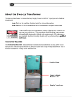
ELECTRICAL INPUT
CONNECTIONS
Before installing the machine, check that the input sup-
ply voltage, phase, and frequency are the same as the
machine’s voltage, phase, and frequency as specified
on the machine’s rating plate on the Case Front
Assembly Control Panel. Connect input power supply
by removing the rear access panel and connecting to
the three line terminals on the input panel. See Figure
A.2 for location of the machine’s input cable entry
opening and reconnect panel assembly for dual volt-
age machines.
Read entire Installation Section before installing the
MULTI-SOURCE.
SAFETY PRECAUTIONS
STACKING HOLE
STACKING PIN
U
V
W
Rear Panel
FIGURE A.1. - Stacking the MULTI-SOURCE
FIGURE A.2. - Input Power Supply Connection
ELECTRIC SHOCK can kill.
• Have an electrician install and service
this equipment.
• Turn the input power off at the fuse box
before working on equipment.
• Do not touch electrically hot parts.
• The Multi-Source power supply should not be used if
the green Safe Output light is not lit. The machine is
designed to open its input contactor if output voltage
peaks exceed the limits set by certain approval
agencies. If the Safe Output light is on, the output
voltage is within it designed operating range.
-------------------------------------------------------------------
WARNING
FALLING EQUIPMENT can cause
injury.
• Two Multi-Source machines can be
stacked.
• Lift only with equipment of adequate
lifting capacity.
• Be sure machine is stable when lifting.
• Do not stack more than two high.
• Do not stack the Multi-Source on top of any other
machine.
---------------------------------------------------------------------
WARNING

INSTALLATION
A-4 A-4
MULTI-SOURCE
Return to Section TOC Return to Section TOC Return to Section TOC Return to Section TOC
Return to Master TOC Return to Master TOC Return to Master TOC Return to Master TOC
FUSE AND WIRE SIZES
Protect the input circuit with the super lag fuses or
delay type circuit breakers listed on the Technical
Specifications page of this manual for the machine
being used. They are also called inverse time or ther-
mal/magnetic circuit breakers.
DO NOT use fuses or circuit breakers with a lower amp
rating than recommended. This can result in nuisance
tripping caused by inrush current even when machine
is not being used for welding at high output currents.
Use input and grounding wire sizes that meet local
electrical codes, or see the Technical Specifications
page in this manual.
INPUT AND GROUNDING
CONNECTIONS
Note: A qualified electrician should connect the
input power supply leads.
Input conductor is brought into the machine input box
area through a hole in the rear panel sized to accom-
modate 2" (trade size) conduit and fittings. This is more
than adequate for the largest conductors required.
Conductors must be lugged to attach to the three 3/8"
studs on the input reconnect panel and the 5/16"
ground stud marked with the symbol . The input volt-
age supplied determines the position required for the
reconnect panel jumper. The three ranges on the stan-
dard machine are 380-415, 440-460 and 550-575. The
machine is rated for 50 and 60 Hz operation. See the
Input Connection Diagram located on the inside of
Case Back Input Access Door.
The conductor and fuse sizes in the Technical
Specification Section), are per the National Electrical
Code. The sizes are in American Wire Gauge (and the
next largest standard metric size in mm
2
). National and
local codes must be consulted before connecting a
machine.
Protect the input circuit with the super lag fuses or
delay type circuit breakers listed in the Technical
Specification Section. (They are also called inverse
time or thermal / magnetic circuit breakers.)
RECONNECT PROCEDURE
Multiple voltage machines are shipped connected to
the highest input voltage listed on the machine’s rating
plate. Before installing the machine, check that the
Reconnect Panel in the Input Box Assembly is con-
nected for the proper voltage.
Failure to follow these instructions can cause immedi-
ate failure of components within the machine.
-----------------------------------------------------------
To reconnect a multiple voltage machine to a different
voltage, remove input power and follow the input
Connection Diagram located on the inside of the Case
Back Input Access Door. This connection diagram is
shown below.
CAUTION
WARNING
FIGURE A.3. - Input Connection Diagram
All input power must be electrically discon-
nected before touching reconnect panel.
1. Mount the movable reconnect bar to
the stationary reconnect panel as
shown, and secure firmly with the
three hex nuts provided.
2. Connect L1, L2, and L3 input supply
lines to the input side of the recon-
nect panel as shown.
3. Connect terminal marked to ground
per national electrode code.
550-575V Connection
440-460V Connection
380-415V Connection
INPUT
LINES
L3
L2
L1
W
V
U
INPUT
LINES
L3
L2
L1
W
V
U
INPUT
LINES
L3
L2
L1
W
V
U

OUTPUT CONNECTIONS
The Multi-Source has two parallel connected output
studs for positive and negative connections. Each one
is rated to carry the full output current. For its maximum
rated current at 100% duty cycle a minimum size of 4/0
AWG welding cable is recommended.
Connection of Electrode and Work Leads to Output
terminals.
1. Set the POWER ON/OFF Toggle Switch to OFF.
2. Raise the hinged cover protecting the output termi-
nals.
3. Insert the electrode lead up through the elliptical
hole in the machine base below the positive output
terminal. Pull through enough cable to reach the out-
put terminal.
4. Connect electrode lead to the terminal .
5. Tighten the output terminal nut with a wrench.
6. Connect the work lead to the negative output termi-
nal following steps 3-5.
7. Lower the cover to protect the output terminals.
PARALLELING
Machines may be paralleled for increased output. The
S20428 paralleling kit permits paralleling of two MULTI-
SOURCE power supplies for supplying currents of up
to 1000 amps, 100% duty cycle.
MULTI-SOURCE OUTPUT LIMITATIONS
The number of Multi-Weld Converters that may be con-
nected to a single Multi-Source Power Source is deter-
mined by the following formula:
Power Source (Volts x Amps) capacity > 1.1 x Sum
of Converters’ (Volts x Amps) arcs
The number of Multi-Weld 350s, the procedures used
and the combined duty cycle of the arcs are only limit-
ed by the 40,000 (36,000 watts on 50Hz) watt rating of
the Multi-Source supply. The machine is IP-23S rated
and is designed for outdoor applications.
DISTRIBUTION BOX
The Multi-Weld Distribution Box (K1736-1) is available
for interconnection of the Multi-System using the same
“pig-tail” connection method provided with the Multi-
Weld 350 converter. Six cable strain-relief ports are
provided for connection of up to (12) cables for distrib-
ution or “daisy-chain” inter-connection to other boxes.
Four “pig-tail” leads (see below) are included with the
Box.
“PIG TAIL” LEADS AND CONNEC-
TIONS
Accessory “pig tail” leads and Twist-Mate connectors
are available from Lincoln for extra connections to the
Multi-Weld 350 or the Distribution Box:
Order No. Description:
CL012705 22in. (56cm) long 2/0 (70mm
2
) cable
with 0.5in. (13mm) hole lug and cut-off
ends.
K852-70 Twist-Mate male insulated plug for 1/0-
2/0 (50-70mm
2
) cable
K852-95 Twist-Mate male insulated plug for 2/0-
3/0 (70-95mm
2
) cable.
K1759-70 Twist-Mate female insulated recepta-
cle for 1/0-2/0 (50-70mm
2
) cable.
K1759-95 Twist-Mate female insulated recepta-
cle for 2/0-3/0 (70-95mm
2
) cable
INSTALLATION
A-5 A-5
MULTI-SOURCE
Return to Section TOC Return to Section TOC Return to Section TOC Return to Section TOC
Return to Master TOC Return to Master TOC Return to Master TOC Return to Master TOC
FIGURE A.4. - Output Terminal Connections


Return to Master TOC Return to Master TOC Return to Master TOC Return to Master TOC
TABLE OF CONTENTS
- OPERATION SECTION -
Operation...............................................................................................................................Section B
Safety Instructions ......................................................................................................................B-2
General Description ....................................................................................................................B-3
Recommended Equipment/Processes.......................................................................................B-3
Design Features and Advantages...............................................................................................B-3
Recommended Equipment/Connections ...................................................................................B-4
Controls and Settings.................................................................................................................B-4
Section B-1 Section B-1
MULTI-SOURCE

OPERATION
B-2 B-2
MULTI-SOURCE
Return to Section TOC Return to Section TOC Return to Section TOC Return to Section TOC
Return to Master TOC Return to Master TOC Return to Master TOC Return to Master TOC
SAFETY INSTRUCTIONS
ELECTRIC SHOCK can kill.
• Do not touch electrically live parts or
electrode with skin or wet clothing.
• Insulate yourself from work and
ground.
• Always wear dry insulating gloves.
------------------------------------------------------------------------
FUMES AND GASES can be dangerous.
• Keep your head out of fumes.
• Use ventilation or exhaust to remove
fumes from breathing zone.
-------------------------------------------------------
WELDING SPARKS can cause fire or
explosion.
• Keep flammable material away.
• Do not weld on closed containers.
------------------------------------------------------------------------
ARC RAYS can burn eyes and skin.
• Wear eye, ear and body
protection.
------------------------------------------------------------
Only qualified personnel should operate
this equipment. See additional warning
information at the front of this operators
manual.
-----------------------------------------------------------
WARNING
Read and understand this entire section before
operating your machine.

OPERATION
B-3 B-3
MULTI-SOURCE
Return to Section TOC Return to Section TOC Return to Section TOC Return to Section TOC
Return to Master TOC Return to Master TOC Return to Master TOC Return to Master TOC
GENERAL DESCRIPTION
The Multi-Source is designed to supply power to the
Multi-Weld welders. It has a wide range three phase
AC input and can be operated on 50 or 60 Hz. The
Multi-Source output peak voltage regulates against
wide changes in output loading and input line voltage
variations to supply a consistently stable voltage high
enough to allow the Multi-Welds to provide good man-
ual electrode capability.
Primary input voltage taps are selected by a single
movable link on the reconnect panel. Main transformer
auxiliary windings power the firing circuit and fan
motor. The control auxiliary transformer has a single,
wide range primary and is not reconnectable.
The Fan As Needed feature is activated by an output
current of 20 amps DC or a thermostat on the main
transformer iron.
An independent safety circuit on the Control board
monitors the voltage peaks and opens the input con-
tactor if the limit is exceeded. The green Safe Output
light indicates when the machine output voltage is with-
in the safe operating range.
Other indicator lights include the amber Thermal light
that signals when the long term output current limit has
been exceeded. This limit is determined by a thermo-
stat sensing the temperature of the negative output
lead from the secondary coils. The white Power light
indicates when the Control board is energized. The
three lights are high intensity LEDs for improved visi-
bility in daylight.
The Output Power display uses high intensity LEDs to
indicate the percentage of full rated output the machine
is supplying.
Two additional thermostats protect the machine in the
case of fan failure or blocked air flow. The SCR heat
sink thermostat responds first to loss of air flow at nor-
mal output loads. This thermostat will disable the
machine output. The transformer iron rear thermostat
senses that the lamination (and thus the coil insulation)
is over heating (which can happen even if the output is
disabled). This thermostat will interrupt power to the
Control board causing the input contactor to open until
the iron cools.
The only user controls are an on-off toggle Power
switch that energizes the machine and a 10 A cir-
cuit breaker protecting the fan auxiliary against
short circuits.
RECOMMENDED
EQUIPMENT/PROCESSES
The only recommended use for the Multi-Source is to
power the Multi-Weld welders. It is conceivable that
the machine could be used as a constant voltage DC
power supply up to its rating of 40,000 watts (36,000
watts on 50Hz) output. Its output is stable with a wide
range of inductive, resistive and capacitive loads but
each application would have to be tested. The output
is peak voltage regulated and at light resistive loads
(maximum ripple) the average voltage deviates from
peak voltage the most.
The Multi-Weld 350 K1752-1 is the recommended
means by which to control the Multi-Source power sup-
ply. Connections between Multi-Source and Multi-
Weld may be easily made using Twist-Mate male and
female connectors and the K1736-1 distribution box.
The Multi-Weld 350 has multi-process capability and
may be used with manual and semi-automatic
processes. When a wire feeder is required, an LN-25
(K449) is recommended. The Multi-Source 40kW
(36kW on 50Hz) 80VDC buss power source (K1752-1)
is recommended for use in the Multi-Weld system.
DESIGN FEATURES AND ADVAN-
TAGES
• 80 volt peak OCV.
• 40,000 watts of output (36,000 watts on 50Hz) at
100% Duty Cycle.
• 75 volts at 533 amps (75.8 volts at 475 amps on 50
Hz) over 900 amps for 5 seconds without harming
the machine.
• The machine has copper windings and a varnish
dipped transformer for added environmental protec-
tion.
• Sealed external controls
.
• Voltage ratings have been upgraded and used with
higher voltage MOVs.
• Input lines are protected by the most rugged surge
protection we’ve ever used.
• Indicator lights and digital display are extra bright to
enhance visibility outdoors.
• HP_Cooling fan can operate on a wider range of
voltage.

OPERATION
B-4 B-4
MULTI-SOURCE
Return to Section TOC Return to Section TOC Return to Section TOC Return to Section TOC
Return to Master TOC Return to Master TOC Return to Master TOC Return to Master TOC
RECOMMENDED EQUIPMENT/CONNECTIONS
The Multi-weld 350 (K1735-1) is the recommended means by which to control the MULTI-SOURCE power supply.
Connections between the MULTI-SOURCE and the Multi-weld may be easily made using Twist-Mate male and
female connectors and the K1736-1 Distribution box.
1. ON/OFF TOGGLE SWITCH: This toggle
switch turns the machine ON or OFF.
2. CIRCUIT BREAKER:
This 10 amp
breaker protects the 120 VAC fan circuit.
3. AMBER LED:
This
LED indicates that
the temperature of the machine is too
high.
4. WHITE LED:
This
LED indicates that the
control board is energized.
5. GREEN LED:
This LED indicates that the
machines output voltage is within the safe
operating range.
6. DIGITAL METER: Provides the user with
an indication of the percentage of avail-
able power.
For 1/0 Cable
K852-70
K1759-70
K852-90
K1759-90
Twist-Mate Male Connector
Twist-Mate Female Connector
Twist-Mate Male Connector
Twist-Mate Female Connector
For 3/0 Cable
The Multi-weld 350 has multi-process capability and may be used in manual and semi-automatic processes. When
a wire feeder is required an LN-25 (K449) is recommended. The number of Multi-Weld 350s, the procedures used
and the combined duty cycle of the arcs are only limited by the 40,000 watt (36,000 watts on 50 Hz) rating of the
Multi-Source supply. The machine is IP-23S rated and is designed for outdoor applications.
% Output
Output
Thermal
Fan
Power
On
OFF
6
5
3
2
4
1
CONTROLS AND SETTINGS
All operator controls and adjustments are located on the Case Front Assembly of the MULTI-SOURCE. See
Figure B.1. below for the location of each control.
FIGURE B.1. - CONTROL PANEL

Return to Master TOC Return to Master TOC Return to Master TOC Return to Master TOC
TABLE OF CONTENTS
- ACCESSORIES -
Accessories...........................................................................................................................Section C
Factory Installed Options/Accessories.......................................................................................C-2
Field Installed Options/Accessories ...........................................................................................C-2
Section C-1 Section C-1
MULTI-SOURCE

FACTORY INSTALLED OPTIONS /
ACCESSORIES
There are no factory installed options.
FIELD INSTALLED OPTIONS /
ACCESSORIES
K1735-1 Multi-Weld 350, Multi-process controller.
K857, K857-1 Remote control, Control multi-weld
remotely (25 or 100 ft.)
K1736-1 Distribution box, Connects up to 10 Multi-
Welds.
K449 LN-25, Across the arc wire feeder.
K1788-1 Roll Cage, Protect power source, facilitate
moving, store cable.
K1806-1 Multi-Weld Four pack, Mounting / lift rack
for M-S and four M-Ws.
K1807-1 Multi-Weld Eight Pack, Mounting / lift rack
for M-S and eight M-Ws.
S20428 Paralleling Kit, Allows two machines to
equally share double load.
ACCESSORIES
C-2 C-2
MULTI-SOURCE
Return to Section TOC Return to Section TOC Return to Section TOC Return to Section TOC
Return to Master TOC Return to Master TOC Return to Master TOC Return to Master TOC

D-1 D-1
TABLE OF CONTENTS
-MAINTENANCE-
MULTI-SOURCE
Return to Master TOC Return to Master TOC Return to Master TOC Return to Master TOC
Maintenance .........................................................................................................................Section D
Safety Precautions......................................................................................................................D-2
Routine and Periodic Maintenance ............................................................................................D-2
Major Component Locations......................................................................................................D-3

Return to Section TOC Return to Section TOC Return to Section TOC Return to Section TOC
Return to Master TOC Return to Master TOC Return to Master TOC Return to Master TOC
MAINTENANCE
D-2 D-2
MULTI-SOURCE
WARNING
SAFETY PRECAUTIONS
ELECTRIC SHOCK can kill.
• Only qualified personnel
should perform this mainte-
nance.
• Turn the input power OFF at
the disconnect switch or fuse box before working
on this equipment.
• Do not touch electrically charged hot parts.
ROUTINE AND PERIODIC MAINTE-
NANCE
1. Disconnect input AC power supply lines to the
machine before performing periodic maintenance,
tightening, cleaning, or replacing parts. See
Figure D.1.
Perform the following daily:
1. Check that no combustible materials are in the
welding or cutting area around the machine.
2. Remove the debris, dust, dirt, or materials that
could block the air flow to the machine for cooling.
3. Inspect the welding cables for any splits or punc-
tures in the cable jacket, or any condition that
would affect the proper operation of the machine.
Perform Periodically:
Clean the inside of the machine with low pressure air
stream. Clean the following parts. Refer to Figure
D.1.
• Main Transformer.
• Electrode and Work Cable connections.
• SCR rectifier bridge and heat sink fins.
• Control Board.
• Firing Board.
• Fan Assembly.
NOTE: The fan motor has sealed bearings which
require no maintenance.
/