Page is loading ...

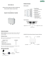
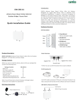
OW-500 A1 / OW-500 A3
eXtreme Power Wave2 4X 2x2 Tri-Band
Outdoor Bridge / Access Point
V4.0
Quick Installation Guide
Product LED Description
Hardware Overview
Products Description
CERIO’s OW-500 A1 built in 5dBi 2.4G(Radio-0) Omnidirectional and
external for 5G (Radio-1) 2N-Type connector and built in 18dBi
5G(Radio-2) Directional Antenna design.
CERIO’s OW-500 A3 built in 5dBi 2.4G(Radio-0) Omnidirectional and
external for 5G (Radio1) and 5G (Radio2) 2N-Type connector design.
Package Contents
Before you start to install this device, please verify your package
that contains the following items:
Package Contents
OW-500 A1
OW-500 A3
Main Unit
x1
x1
PoE Power supply Kit
x1
x1
Quick Installation Guide
x1
x1
Warranty Card
x1
x1
Wall/Pole Mounting Bracket Set
x1
x1
Adjustable Mounting Bracket Set
x1
x1
Note: If any of these items is found missing or damaged, please
contact your local supplier for replacement.
PoE Setup Instructions
OW-500 A1 Overview
OW-500 A3 Overview
Data Out
Power Adapter DC in
Power in
PoE out
OW-500 A1 OW-500 A3
*Note: Radio-0 2.4Ghz does not
display the LED signal function
Power
Eth1
5GHz(Radio1)
5GHz(Radio2)
Eth2
1. Power(Green) :
PoE on and system ready
2. Eth1(Green) :
Eth1 link connection
3. Eth2(Green) :
Eth2 link connection
4. Radio-1 5GHz(Flashing) :
Radio-1 5GHz radio is enabled
5. Radio-2 5GHz(Flashing) :
Radio-2 5GHz radio is enabled
Gigabit ETH1 / PoE in Gigabit ETH2
Pressure Vent
External for 5GHz(Radio1) 2x2 N-Type Connecter
External for 5GHz(Radio2) 2x2 N-Type Connector
Built in 5dBi 2.4GHz(Radio0) 2x2 Omni Antenna
Built in 18dBi 5GHz(Radio2)2x2 Directional Panel
Antenna
External for 5GHz(Radio1) 2x2 N-Type Connecter
Built in 5dBi 2.4GHz(Radio0)2x2 Omni Antenna

Wall/Pole Mounting Bracket Set
Adjustable Mounting Bracket Set
Mounting Instructions
Instructions: Position the mounting bracket in the desired location.
Slide the device down until it is parallel to the bottom. Then locked
with a main unit screw.
Wall Mounting Setup
Pole Mounting Setup
Instructions: Use the provided steel bracket ties to pole mount
device. Use a flathead screwdriver to tightly secure the device in
place.
Adjustable Mounting Instructions
Instructions: Position the mounting bracket in the desired location.
Use the screws to secure the bracket into the position. Use the
adjustable bracket to mount the device on the wall.
Adjustable Wall Mounting Setup
Adjustable Pole Mounting Setup
Instructions: Use the provided U rings to tightly secure on the pole.
Use the adjustable bracket to pole mount the device.
GUI Setting Instructions
Product default IP address : 192.168.2.254
Product default Account : root / Password : default
Set the IP segment of the administrator's computer to be in the same
range as this device for accessing the system. E.g. 192.168.2.100,
after open your Browser enter IP address http://192.168.2.254 in the
URL field Enter GUI management interface. Login message will appear
when you successfully enter the management interface.
Please use default Users name:
“root” and default password
“default” to login.
If you have advanced setting and
more question please refer to our
user manual.
Mounting bracket x1
Steel bracket ties x2
Bracket screw set x2
Main unit screw x1
Adjustable bracket x1
U rings x2
U rings screw nuts set x4
(2)
(1)
(3) (3)
(1)
(1)
(2)
(3)
(2)
/


