Page is loading ...

SM-P00046-A
INSTRUCTION MANUAL
PILOT TYPE 3,5 PORTS
ELECTRIC-MAGNETIC
VALVE
(M)3GD/E1-SERIES
(M)3GD/E2-SERIES
(M)3GD3-SERIES
(M)4GD/E1-SERIES
(M)4GD/E2-SERIES
(M)4GD/E3-SERIES
Individual sub base
type
Manifold type
Please read this instruction manual carefully before using this product,
especially the section describing safety.
Retain this instruction manual with the product for further consultation
whenever necessary.
2ND EDITION

Safety precautions
When designing and manufacturing a device using CKD products, the manufacturer is obligated to
manufacture a safe product by confirming safety of the system comprising the following items:
Device mechanism
Pneumatic or water control circuit
Electric control that controls the above
It is important to select, use, handle, and maintain the product appropriately to ensure that the CKD
product is used safely.
Observe warnings and precautions to ensure device safety.
Check that device safety is ensured, and manufacture a safe device.
1. This product is designed and manufactured as a general industrial machine part.
It must be handled by someone having sufficient knowledge and experience.
2. Use this product within its specifications.
This product cannot be used beyond its specifications. Additionally, the product must not be
modified or machined.
This product is intended for use in general industrial devices and parts. Use beyond such
conditions is not considered. Consult with CKD for details when using the product beyond the
unique specification range, outdoors, or in the following conditions or environments. In any case,
measures for safety shall be provided when the vavle malfunctions.
Use for special applications requiring safety including nuclear energy, railroad, aviation, ship,
vehicle, medical equipment, equipment or applications coming into contact with beverage or
food, amusement equipment, emergency shutoff circuits, press machine, brake circuits, or
for safeguard.
Use for applications where life or assets could be adversely affected, and special safety
measures are required.
3. Observe corporate standards and regulations, etc., related to the safety of
device design and control, etc.
SO4414, JIS B 8370 (pneumatic system rules)
JFPS2008 (principles for pneumatic cylinder selection and use)
Including High Pressure Gas Maintenance Law, Occupational Safety and Sanitation Laws,
other safety rules, standards and regulations, etc.
4. Do not handle, pipe, or remove devices before confirming safety.
Inspect and service the machine and devices after confirming safety of the entire system
related to this product.
Note that there may be hot or charged sections even after operation is stopped.
When inspecting or servicing the device, turn off the energy source (air supply or water supply),
and turn off power to the facility. Release any compressed air from the system, and pay enough
attention to possible water leakage and leakage of electricity.
When starting or restarting a machine or device that incorporates pneumatic components,
make sure that system safety, such as pop-out prevention measures, is secured.

5. Observe warnings and cautions on the pages below to prevent accidents.
The safety cautions are ranked as "DANGER", "WARNING" and "CAUTION" in
this section.
When a dangerous situation may occur if handling is mistaken
leading to fatal or serious injuries, or when there is a high degree
of emergency to a warning.
When a dangerous situation may occur if handling is mistaken
leading to fatal or serious injuries.
When a dangerous situation may occur if handling is mistaken
leading to minor injuries or physical damage.
Note that some items described as "CAUTION" may lead to serious results depending on
the situation. In any case, important information that must be observed is explained.
Precautions with regard to guarantee
Guarantee period
The guarantee period of our product shall be one (1) year after it is delivered to the place specified
by the customer.
Guarantee coverage
If any failure for which CKD CORPORATION is recognized to be responsible occurs within the
above warranty period, a substitute or necessary replacement parts shall be provided free of
charge, or the product shall be repaired free of charge at the plant of CKD CORPORATION.
However, the guarantee excludes following cases:
Defects resulting from operation under conditions beyond those stated in the catalogue or
specifications.
Failure resulting from malfunction of the equipment and/or machine manufactured by other
companies.
Failure resulting from wrong use of the product.
Failure resulting from modification or repairing that CKD CORPORATION is not involved in.
Failure resulting from causes that could not be foreseen by the technology available at the time
of delivery.
Failure resulting from disaster that CKD is not responsible of.
Guarantee stated here covers only the delivered products. Any other damage resulting from failure of
the delivered products is not covered by this guarantee.
Confirmation of product compatibility
Our customer shall be responsible of confirming compatibility of our product used in our customer’s
system, machinery or device.

UNPACKING (Chapter 3.)
Bags containing solenoid valves should be opened only when you
are ready to connect the valves to the pipes immediately afterward.
If bags are opened before the valves are ready to be connected
to the pipes, the entry of foreign matter from the piping ports
could cause the solenoid valves to fail or malfunction.
INSTALLATION (Chapter 4.)
If you have to use the product under conditions that are different
from the specified conditions or if you intend to use the product
for a special application, be sure to consult us about the product
specifications before using the product.
INSTALLATION ENVIRONMENT (Section 4.1.)
a) In a dusty environment, foreign matter may enter even through
the exhaust port.
The movement of the solenoid valve causes a respiratory
action at the exhaust port, which may cause inhalation of
foreign matter around the exhaust port. This potential
situation would be worse if the exhaust port is facin
g
upward.
Attach a silencer to the exhaust port or have the exhaust port
face downward.
b) Do not keep water or coolant dripping to the solenoid valve
system constantly.
In case that the solenoid valve system is used under the
conditions with constant water splash, protect it by a cover or
install it inside a enclosure.
If the cylinder rod is splashed with cutting oil, the oil may
penetrate through the cylinder into the secondary side piping of
the solenoid valve. This must be prevented to avoid
malfunctions. Consult us for preventive measures.
c) The coils will produce heat.
Particularly if the solenoid valve system is installed in a control
board or if the solenoid coils need to be energized for a long
time, consider providing sufficient ventilation to release the
heat. The coils can get very hot.
d) Do not use the solenoid valve system in an atmosphere that
includes a corrosive gas such as the sulfur dioxide gas or
solvent vapors.
e) Vibrations and shocks
Do not subject the solenoid valve system to vibrations 50m/s
2
or stronger or shocks 300m/s
2
or stronger.
f) Do not use the normal type solenoid valves for an application
that requires conformity with explosion-proof specifications.
Choose explosion-proof solenoid valves instead.
INSTALLATION (Section 4.2.)
When installing a solenoid valve unit, never attempt to hold it in
position by means of the pipes connected to it.
Fix the solenoid valve by applying the mounting screws
and/or mounting plate to the solenoid valve.
When mounting this product on the DIN rail, check the
strength
If the strength is insufficient, mount the manifold base
directly.

PIPING (Section 4.3.)
a) Observe the recommended tightening torque when connecting
pipes.
Observing the recommended tightening torque prevents air
leakage and damage to the screw threads. To prevent
damage to the screw threads, first use your hand to lightly
tighten the screw and then use a tool to tighten the screw to the
recommended torque.
b) Make sure that the pipes will not be disconnected at the joints by
mechanical movements, vibrations or tension.
If the exhaust piping of the pneumatic circuit is disconnected,
the actuator speed control is disabled.
If the above happens to a chuck holding mechanism, the chuck
will open. The inadvertent opening of the chuck may cause a
serious accident.
c) When supplying the compressed air for the first time after
completing the piping, be sure to check every joint in the piping
for air leakage.
d) When supplying the compressed air for the first time after
completing the piping, increase the air pressure gradually but
never introduce a highly-pressurized air suddenly.
Asudden introduction of a highly-pressurized air may
disconnect pipes at joints and/or cause the tubes to jump
around, any of which may cause an injury.
e) Do not decrease the inside diameter of the piping from any of
the solenoid valve exhaust ports to a diameter less than the
exhaust pipe connecting port size.
Normal operation of the actuator depends on the smoothness
of the exhaust flow. With a manifold system, a restriction to
the exhaust flow may prevent normal operation of other
solenoid valves.
f) Removal of foreign matter
Rust and other foreign matter in the pneumatic circuit may
cause a malfunction or leakage from the valve seat. Insert a
filter (maximum allowable particle size 5 m or less) immediately
upstream of the solenoid valve.
g) Air supply
Do not restrict the flow of air through the air supply piping.
With a manifold system with multiple stations, a drop in the
air supply pressure may cause trouble through a delay in
the operation timing.
WIRING (Section 4.4.)
When carrying out electrical connections, please perform
disassembling and assembling work after reading the Instruction
Manual carefully and with full understanding of its contents.
Your understanding of the structure of solenoid valve and its
operation principle is required in order to secure the safety.
Before supplying the power, check the power supply voltage and
the current type (AC or DC).

MANUAL OPERATION (Section 5.2.)
a) After using the manual override, be sure to reset the manual
override to the original (OFF) position before resuming the
operation of the device.
b) Before using the manual override, make sure that nobody is
present near the cylinder to be activated.
c) After an operation, be sure to release the lock to turn the
manual override OFF.
The lock is released (the manual override turned OFF) if the
manual override protection cover is closed.
AIR QUALITY (Section 5.3.)
a) Do not supply anything other than compressed air.
b) Supply clean compressed air without any mixture of corrosive
gas.
a) Compressed air usually contains a large amount of drain,
oxidized oil, tar, foreign matter, and rust from the piping. Filter
out those elements in the supplied air because they may cause
a malfunction and decrease service life. In addition, clean the
exhaust before it is released to the air to minimize pollution.
b) Once you have lubricated a pre-lubricated valve, the valve is no
longer capable of running without being lubricated from the
outside. Do not leave the valve without lubrication. Keep it
lubricated.
c) Do not use spindle oil or machine oil. They induce
expansion of the rubber parts, which will cause malfunction.

ELECTRIC CIRCUIT (Section 5.4.)
a) Check for the presence of any current leak from the external
control device because it may cause malfunction.
When a programmable controller or a similar control device is
used, a current leak may prevent the normal returning of the
valve when the solenoid is de-energized.
b) Restriction on current leak
When controlling solenoid valves using a programmable
controller or a similar control device, make sure that the
current leak in the programmable controller output is equal to
or less than the level shown in the table below. A current leak
larger than the allowable level may cause malfunction.
PERIODIC INSPECTION (Section 6.1.)
Before providing maintenance service, cut the power and the supply
of compressed air and confirm the residual pressure is released.
The above is required to ensure safety.
Regularly perform the daily and periodic inspections to correctly
maintain product performance.
If the product is not correctly maintained, product performance
may deteriorate dramatically, resulting in a shorter service life,
fractures of components, and malfunctions.
DISASSEMBLY AND ASSEMBLY (Section 6.2.)
Before increase or decrease block of manifold, cut the power and
the supply of compressed air.
Please avoid disassembling and reassembling the solenoid
valve, otherwise the sealing and drip proof performance
may deform.
Disassembled and Reassembled product by the customer
will not be guaranteed.
ADDITIONAL INSTALLATION OF A VALVE UNIT TO A REDUCED WIRING TYPE MANIFOLD
(Section 6.3.)
When disassembling or assembling the manifold, perform it after
reading the Instruction Manual carefully and with full
understanding of its contents.
You are required to understand the structure of solenoid valve
and its operation principle to secure the safety.
A level of 2nd Class or more of Pneumatics Technology
Certification is required.
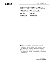
AC100V 2.0 mA or less
DC12V 1.5 mA or less
DC24V 1.8 mA or less
Contact C
R
Programmable
controller side
Solenoid valve
CR circuit

PRODUCT
INDEX
(M)3GD/E1 , (M)3GD/E2 , (M)3GD3
(M)4GD/E1 , (M)4GD/E2 , (M)4GD/E3
Pneumatic 3,5-port solenoid valve
Instruction Manual No. SM-P00046-A
1. PRODUCT·····························································································8
2. PORT INDICATION AND SI UNIT SYSTEM
2.1 Port indication··············································································11
2.2 Conversion between SI unit and conventional unit ·····················11
3. UNPACKING ·······················································································12
4. INSTALLATION
4.1 Installation environment·······························································13
4.2 Installation····················································································14
4.3 Piping···························································································19
4.4 Wiring···························································································23
5. PROPER OPERATION
5.1 Description of operation·······························································42
5.2 Manual operation·········································································45
5.3 Air quality·····················································································47
5.4 Electric circuit···············································································48
6. MAINTENANCE
6.1 Periodic inspection·······································································49
6.2 Disassembly and reassembly······················································50
6.3 Additional Installation of a Valve Unit
to a reduced Wiring type Manifold ·······························51
7. TROUBLE SHOOTING·······································································55
8. PRODUCT SPECIFICATIONS AND HOW TO CODE MODEL NUMBERS
8.1 Product specifications··································································56
8.2 How to code model numbers·······················································60
8.3 Option ··························································································76
8.4 Accessories ·················································································77
8.5 Kit Parts·······················································································78

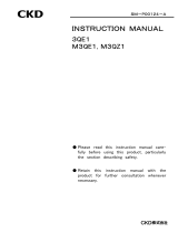
PRODUCT
1. PRODUCT
base porting type
body porting type
Mounting plate
Individual wiring type manifold Reduced wiring type manifold
(The sketch shows DIN rail mount type)
Common terminal stand(T10) Common terminal stand( 11) D-sub connector( 30)
M3 thread type Push-in fitting type

PRODUCT
Flat cable connector(T50) Flat cable connector (T51)
Serial transmission slave unit (T6*)
DIN terminal box(B) Socket with cover(E*J)
37
34

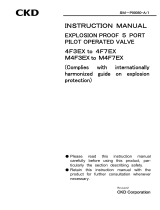
PRODUCT
No.
1 Lead wire
No specification about the polarities.
2 Electric component cover
The green power indicator light on the top surface is lit when the power is
surplied to the coil. (With E-type and A-type connectors only.)
3 Coil assembly
It varies depending on electric wire connection type and voltage.
This part is not compatible with No.35.
4 Manual override protection
cover
The protection cover prevents accidental operation of the manual ovveride.
The user must open the cover before operating the manual override.
5 Manual override
Allows a non-lock type operation (push and release) as well as a lock type
(push and lock) operation.
6 Individual valve
7 Individual valve mounting
screw
Two screws are provided for each individual valve so as to fix the individual
valves to various bases.
8
Sub plate
In case of an individual specification, assemble this sub base.
9 Piping port
“1(P)”, “3(R2)/5(R1)”, and “2(B)/4(A)” show the supply, exhaust, and output
ports, respectively.
10 Joint
A replaceable cartridge type one-touch joint.
11 Stopper plate
Secures cartridge type joints or like.
This part is not compatible with No.17.
12 Piping adaptor
Supplied attached to the body porting individual valve.
13 Mounting hole
For direct mounting
14 Mounting plate
Used for vertical mounting of the body porting individual valve.
15 manifold base
16 Masking plate
Removed when an additional valve unit is installed.
17 Joint stopper plate
Secures cartridge type joints or like.
This part is not compatible with No.11.
18 Electric component block
Includes and secures a printed circuit board with intermediate connectors.
19 Wiring cover
Protects the cables inside. Keep the cover closed when using the valves.
20 DIN rail
21 DIN rail mounting screw
Fix the entire manifold in place on the DIN rail.
One holder is used at each of the two ends of the base.
22 Holder
The holders are used together with the DIN rail mounting screw.(With
4G2/4G3 only)
23 Spare cable
For additional valve installation.
24 Terminal block
A set of terminals to control the valves mounted on the manifold.
25 Cover
Can be opened when wiring. To avoid electric shock, be sure to close it before
energization.
26 Indicates the layout of the
terminal stand
Terminal block layout drawing Indicates the layout of the terminal block.
Paper can be removed for use as a TAG for taking notes.
27 D-sub 25-pin connector
Locks the mating connector (M2.6).
28 Mounting screw
Loosened to allow changing the direction for leading out the connected cable;
tightened to lock the direction.
29 The screw for detent
Loosened to allow changing the direction for leading out the connected cable;
tightened to lock the direction.
30 Power terminal block
Used when an external power supply is required.
31 Power polarity marking
32 Power indicator light
Lit when the power is supplied with right polarities.
33 Flat cable connector
A set of terminals to control the valves mounted on the manifold.
34 Serial transmission slave unit
This is a slave station dedicated to a CKD-made manifold.
35 DIN terminal box
A green power indicator lamp is lit while the solenoid is energized.
36 Coil assembly
This coil assembly is for the DIN terminal box type only.
This part is not compatible with No.3.
37 Socket with cover
Comes with a covered cabtyre cable; can be used with the E-type connector.

SI UNIT
2. PORT INDICATION AND SI UNIT SYSTEM
2.1 Port Indication
Each piping port is marked with ISO and JIS conformable piping port indication codes.
Application ISO JIS
Supply port 1 P
Output port 4 A
Output port 2 B
Exhaust port 5 R1
Exhaust port 3 R2
Installing position of the solenoid valve is free. The position of the 4(A) and 5(R1) ports for 4G series
are in reverse with 2(B) and 3(R2) ports respectively, compared with the 4K series. To avoid
malfunction, please confirm the port symbol before piping.
2.2 Conversion between SI unit and Conventional Units
In this manual, values are expressed using the International System of Units (SI).
Use the table below to convert them into values expressed in conventional units.
Table of conversion between SI units and conventional units
(The values printed in Bolds fonts are values given in the International System of Units (SI)):
Force
N dyn kgf
1 1×10
5
1.01972×10
-1
1×10
-5
1 1.01972×10
-6
9.80665 9.80665×10
5
1
Stress
Pa or N/m
2
MPa or N/mm
2
kgf/mm
2
kgf/cm
2
1 1×10
-6
1.01972×10
-7
1.01972×10
-5
1×10
6
1 1.01972×10
-1
1.01972×10
9.80665×10
6
9.80665 1 1×10
2
9.80665×10
4
9.80665×10
-2
1×10
-2
1
1Pa=1N/m
2
, 1MPa=1N/mm
2
Pressure
Pa kPa MPa bar kgf/cm
2
atm mmH2O MmHg or Torr
1 1×10
-3
1×10
-6
1×10
-5
1.01972×10
-5
9.86923×10
-6
1.01972×10
-1
7.50062×10
-3
1×10
3
1 1×10
-3
1×10
-2
1.01972×10
-2
9.86923×10
-3
1.01972×10
2
7.50062
1×10
6
1×10
3
1 1×10 1.01972×10 9.86923 1.01972×10
5
7.50062×10
3
1×10
5
1×10
2
1×10
-1
1 1.01972 9.86923×10
-1
1.01972×10
4
7.50062×10
2
9.80665×10
4
9.80665×10 9.80665×10
-2
9.80665×10
-1
1 9.67841×10
-1
1×10
4
7.35559×10
2
1.01325×10
5
1.01325×10
2
1.01325×10
-1
1.01325 1.01323 1 1.03323×10
4
7.60000×10
2
9.80665 9.80665×10
-3
9.80665×10
-6
9.80665×10
-5
1×10
-4
9.67841×10
-5
1 7.35559×10
-2
1.33322×10
2
1.33322×10
-1
1.33322×10
-4
1.33322×10
-3
1.35951×10
-3
1.31579×10
-3
1.35951×10 1
1Pa=1N/m
2
Example (converting a pressure value):
1kgf/cm
2
0.980665Mpa 1MPa
1.01972 10kgf/cm
2

UNPACKING
3. UNPACKING
Bags containing solenoid valves should be opened only when you
are ready to connect the valves to the pipes immediately afterward.
If bags are opened before the valves are ready to be connected
to the pipes, the entry of foreign matter from the piping ports
could cause the solenoid valves to fail or malfunction.
a) Check the model number imprinted on the product to make sure that the product you received is
exactly the product you ordered.
b) Check the exterior of the product for any damage.
c) Before using the product, read the supplied documentation.

INSTALL
A
TION
4. INSTALLATION
If you have to use the product under conditions that are different
from the specified conditions or if you intend to use the product for a
special application, be sure to consult us about the product
specifications before using the product.
4.1 Installation environment
a) In a dusty environment, foreign matter may enter even through
the exhaust port.
The movement of the solenoid valve causes a respiratory
action at the exhaust port, which may cause inhalation of
foreign matter around the exhaust port. This potential
situation would be worse if the exhaust port is facin
g
upward.
Attach a silencer to the exhaust port or have the exhaust port
face downward.
b) Do not keep water or coolant dripping to the solenoid valve
system constantly.
In case that the solenoid valve system is used under the
conditions with constant water splash, protect it by a cover or
install it inside a enclosure.
If the cylinder rod is splashed with cutting oil, the oil may
penetrate through the cylinder into the secondary side piping of
the solenoid valve. This must be prevented to avoid
malfunctions. Consult us for preventive measures.
c) The coils will produce heat.
Particularly if the solenoid valve system is installed in a control
board or if the solenoid coils need to be energized for a long
time, consider providing sufficient ventilation to release the
heat. The coils can get very hot.
d) Do not use the solenoid valve system in an atmosphere that
includes a corrosive gas such as the sulfur dioxide gas or
solvent vapors.
e) Vibrations and shocks
Do not subject the solenoid valve system to vibrations 50m/s
2
or stronger or shocks 300m/s
2
or stronger.
f) Do not use the normal type solenoid valves for an application
that requires conformity with explosion-proof specifications.
Choose explosion-proof solenoid valves instead.

INSTALL
A
TION
4.2 Installation
When installing a solenoid valve unit, never attempt to hold it in
position by means of the pipes connected to it.
Fix the solenoid valve by applying the mounting screws and/or
mounting plate to the solenoid valve.
If you choose to mount the solenoid valve manifold on a DIN rail,
make sure that the DIN rail is strong enough.
If the strength is insufficient, mount the manifold body
directly.
Please secure enough space around the solenoid valve for mounting, dismounting and piping work.
4.2.1 How to install body porting individual valve
1) For direct mount
For body porting individual valve 4GD2/4GD3 series, through hole or internal thread hole is available for
installation.
If a screw hole is used, recommended tightening torque is 0.7 - 1.2N m.
(For the 4GD1 series,
through holes only)
4GD1 Series 4GD2 Series 4GD3 Series
Mounting hole shape
4GD2 Series 4GD3 Series
Through hole
thread hole common Through hole Thread hole
Mounting
hole
sectional
view
3.2
Thread hole
8 spot facing depth 5

INSTALL
A
TION
2) How to install Mounting plate(Option "P")
For mounting plate of body porting individual valve, installation method may differ depending on single,
double or 3-position. Incorrect installation may cause failures. For DIN terminal box type, it is restricted to
the single solenoid type.
4GD1 Series
4GD2 Series
4GD3 Series
5(R1) side 5(R1) side 5(R1) side
5(R1) side 5(R1) side 5(R1) side
5(R1) side 5(R1) side 5(R1) side

INSTALL
A
TION
4.2.2 Mounting method of individual valve sub base type
4GE1 Series 4GE2 Series
4GE3 Series
2 3.2 Mounting hole
2 4.4 Mounting hole
2 4.3 Mounting hole

INSTALL
A
TION
4.2.3 How to install manifold
1) How to install DIN rail
A DIN rail mounting type manifold (Option symbol “D”) or a direct mounting type manifold which is
modified using the DIN rail kit can be mounted on the DIN rail.
If not mounted correctly, this may cause the
manifold to drop or be damaged. Carefully check this point.
Fix the DIN rail on the mounting surface at
intervals of 50 mm when using it under the environment of vibration or impact. Before starting the
operation, make sure that the installation status is correct.
M4G1 Series
M4G2 / M4G3 Series
1.
Mounting the holder
(The tapping screw is tightened to
prevent dropping off.)
2.
Temporarily tighten set screw.
3.
Set the jaws onto the DIN rail in
the order of (1) and (2).
4.
Press in the direction of (3).
5.
Tighten the set screw.
Tightening torque 0.7 to 1.0 N m
Lock nut
Mounting
screws
Mounting
screws
Holder
Tapping screw
Tighten the lock nut.
The DIN rail could deform if the
tightening torque is too high.
Tightening torque 0.3 to 0.7 N m
DIN rail
DIN rail

INSTALL
A
TION
2) For direct mount
M4G2/M4G3 series, through hole or internal thread hole is available for installation.
When using the internal threads, select a mounting bolt that is screwed in by 10 threads or more, and
note the tightening torque. Tightening torque 1.0 to 1.5 N m (For M4G1 series, through holes only.)
If not
mounted correctly, this may cause the damage to the screws.
M4G2 / M4G3 Series
Mounting hole shape(Secion)
Internal pilot(Standard)
body porting [M4GD] base piping [M4GE] External pilot("K1")
M4G2
M4G3
Through hole
/thread hole common

INSTALL
A
TION
4.3 Piping
a) Observe the recommended tightening torque when connecting
pipes.
Observing the recommended tightening torque prevents air
leakage and damage to the screw threads. To prevent
damage to the screw threads, first use your hand to lightly
tighten the screw and then use a tool to tighten the screw to the
recommended torque.
b) Make sure that the pipes will not be disconnected at the joints by
mechanical movements, vibrations or tension.
If the exhaust piping of the pneumatic circuit is disconnected,
the actuator speed control is disabled.
If the above happens to a chuck holding mechanism, the chuck
will open. The inadvertent opening of the chuck may cause a
serious accident.
c) When supplying the compressed air for the first time after
completing the piping, be sure to check every joint in the piping
for air leakage.
d) When supplying the compressed air for the first time after
completing the piping, increase the air pressure gradually but
never introduce a highly-pressurized air suddenly.
Asudden introduction of a highly-pressurized air may
disconnect pipes at joints and/or cause the tubes to jump
around, any of which may cause an injury.
e) Do not decrease the inside diameter of the piping from any of
the solenoid valve exhaust ports to a diameter less than the
exhaust pipe connecting port size.
Normal operation of the actuator depends on the smoothness
of the exhaust flow. With a manifold system, a restriction to
the exhaust flow may prevent normal operation of other
solenoid valves.
f) Removal of foreign matter
Rust and other foreign matter in the pneumatic circuit may
cause a malfunction or leakage from the valve seat. Insert a
filter (maximum allowable particle size 5 m or less) immediately
upstream of the solenoid valve.
g) Air supply
Do not restrict the flow of air throu
g
h the air suppl
y
pipin
g
.
With a manifold system with multiple stations, a drop in the air
supply pressure may cause trouble through a delay in the
operation timing.
Tightening torque
Joint screw Tightening torque N m
M5 0.5 to 1
Rc1/8 3 to 5
Rc1/4 6 to 8
Rc3/8 13 to 15
/