Page is loading ...

Service Instructions
BARE ROTARY SCREW COMPRESSOR
REPLACEMENT
Models TDSH/TDSL - XJS/XJF - SGC
Form 070-660 SM (NOV 2008)
SERVICE MANUAL
File: SERVICE MANUAL - Section 70
Replaces: S70-660 SM (DEC 2003)
Dist: 3, 3a, 3b, 3c
Revised: February 25, 2010 - p. 17
July 19, 2010 - p. 23
Please check www.johnsoncontrols.com/frick for the latest version of this publication.
Please check www.johnsoncontrols.com for the latest version of this publication.
Table of Contents
TDSH/TDSL COMPRESSOR REPLACEMENT ...................................................................................................................................2
TDSH 163 and 193 ECONOMIZER PLUGS .......................................................................................................................................3
Figure 1. TDSH 163 & 193 Liquid Injection and Economizer Plugs before January 1994 ..........................................................3
Figure 2. TDSH 163 & 193mm Economizer Port and Plug after January 1994 .........................................................................4
Table 1. TDSH Flange Bolt Torque ..........................................................................................................................................4
Figure 3. 163/193mm Compressor Ports Locations .................................................................................................................5
Figure 4. 233mm Compressor Ports Locations .......................................................................................................................6
Figure 5. 283mm Compressor Ports Locations ........................................................................................................................7
REPLACING TDSL 3-STEP WITH A 4-STEP COMPRESSOR ............................................................................................................8
Figure 6. TDSL 283S & 283L 3-Step P & I Diagram with 4-Step Machine (bottom view) ........................................................8
Figure 7. TDSL 283S/283L 4-Step P & I Diagram with 4-Step Machine (bottom view) ...........................................................8
Figure 8. TDSL 283XL 3-Step P & I Diagram with 4-Step Machine (bottom view) .................................................................9
Figure 9. TDSL 283XL 4-Step P & I Diagram with 4-Step Machine (bottom view) .................................................................9
Table 2. RDB/TDSL Capacity Control Sequence ......................................................................................................................9
REPLACING TDSH 355 WITH TDSB 355 ........................................................................................................................................10
REPLACING TDSH 355 WITH TDSH 355 ........................................................................................................................................10
Figure 10. Booster 1/8” Orice Fitting ..................................................................................................................................10
Figure 11. 355mm Compressor Ports Locations .................................................................................................................... 11
XJS COMPRESSOR REPLACEMENT .............................................................................................................................................. 12
XJS/XJF SLIDE VALVE SOLENOID VALVES ................................................................................................................................... 12
Figure 12. XJS Discharge Housing Mounted Solenoid .......................................................................................................... 13
Figure 13. RXB Unit Housing Mounted Solenoid ................................................................................................................... 13
RXF/XJF MOTOR & COMPRESSOR REPLACEMENT PROCEDURE .................................................................................................14
Figure 14. Weigh replacement motor ...................................................................................................................................14
Figure 15. Hydraulic piston supports motor weight ..............................................................................................................14
Figure 16. Shim motor feet to less than .002 inch gap ......................................................................................................... 15
Figure 17. Set replacement compressor and motor assembly on separator ange ............................................................... 15
Table 3. XJS/XJF Motor Weights ..........................................................................................................................................16
Table 4. XJS/XJF Flange Bolt Torque .................................................................................................................................... 16
SLIDE VALVE POTENTIOMETERS vs LINEAR TRANSMITTERS FOR RXF/RXB UNITS. .................................................................... 17
Figure 18. Slide Valve Potentiometers vs Linear Transmitters on Remanufactured XJF Compressors .................................. 17
Figure 19. Installation of Precision Engineering Vi Control Valves and Gaskets, RXB & RXF Pkgs ........................................18
Vi CONTROL VALVES AND GASKETS ........................................................................................................................................... 18
Figure 20. Installation of Danfoss Vi Control Valves and Gaskets, RXB & RXF Pkgs ............................................................. 19
RWF MOTOR & COMPRESSOR REPLACEMENT PROCEDURE .......................................................................................................20
Figure 21. Weigh replacement motor ...................................................................................................................................20
Figure 22. Hydraulic piston supports motor weight ..............................................................................................................20
Figure 23. Shim motor feet to less than .002 inch gap ......................................................................................................... 21
Figure 24. Set replacement compressor and motor assembly on separator ange .............................................................. 21
Table 5. SGC Motor Weights.................................................................................................................................................22
Table 6. SGC Flange Bolt Torque .......................................................................................................................................... 22
RETURNING THE OLD COMPRESSOR .......................................................................................................................................... 23
Table 7. Compressor Weights (less coupling) ........................................................................................................................23

TDSH/TDSL COMPRESSOR REPLACEMENT
SERVICE MANUAL
070-660 SM (NOV 08)
Page 2
TDSH/TDSL COMPRESSOR REPLACEMENT
The following procedure is required when a compressor
is replaced in the eld:
NOTE: Refer to current Installation-Operation-
Maintenance Manual of your unit for detailed
shutdown/start-up instructions.
11. Verify that main power to the unit is disconnected.
Lockout and tag the switch.
12. Close suction and discharge service valves, also
liquid injection and economizer service valves, as
applicable.
3. Slowly vent separator to low-side system pressure
using the bypass line on suction trap.
NOTE: Recover or transfer all refrigerant vapor, in
accordance with local ordinances, before opening
to atmosphere. The separator must be equalized to
atmospheric pressure.
To prevent injury or damage to
components, and for complete
details regarding pressurized
refrigerant vapor transfer and recovery, see the
current Installation-Operation-Maintenance Manual
for your unit.
14. Remove all tubing, piping, and wiring that is
connected to the compressor.
15. Disconnect the coupling from the motor shaft.
16. Support the compressor by attaching a crane,
or other appropriate lifting device, to the lifting
eyebolts supplied with the compressor. Remove
bolts from the compressor feet and discharge ange.
Carefully remove compressor from base. See Table
7 for compressor weights. Save any existing shims.
17. Thoroughly clean the replacement compressor
and motor feet and mounting pads of burrs and
other foreign matter to ensure rm seating of the
compressor.
18. Clean the discharge flange surfaces on the
compressor and separator. Clean mounting surfaces
of compressor feet.
CAUTION
19. Support the new compressor in the same fashion as
the old compressor. Remove the solid plate from the
discharge ange. The new gasket between the ange
and solid plate will be used to seal the compressor
to the separator ange. Make sure the gasket does
not restrict gas ow. (Contact Baltimore Parts Center
for replacement gaskets, Ph:800-336-7264)
10. Tighten bolts in the discharge ange connection
to the compressor using a star pattern. Lube bolts
then nger tighten all bolts, then torque to 1/3 of
value (See Table 1) in star pattern increasing by 1/3’s
to full torque. Measure the clearance between the
compressor feet and the base plate with a feeler
gauge. If no clearance is evident, remove compressor
and install a second gasket on discharge ange.
Retorque ange.
11. Measure the clearance between the compressor
feet and the base plate with a feeler gauge. Shim
any compressor feet that exhibit a gap (gauge
reading + .002”). A pry or jack can be used to lift
the compressor .002”. Reinstall and tighten bolts in
feet to the support base and torque the mounting
bolts to 250 ft-lb.
12. Install tubing, piping and wiring. Use the suction
gasket supplied with the new compressor. It is
located between solid plate and suction port. Refer
to the Installation, Operation and Maintenance
manual for P & I diagram.
13. Reinstall drive coupling. See current Installation-
Operation-Maintenance Manual of your unit for
coupling alignment procedure and bolt torques.
NOTE: If motor was disconnected or changed, motor
rotation must be checked before drive coupling is
installed.
14. The shaft alignment must be measured and aligned
to .004” total indicator reading. Verication of the
alignment is necessary after the compressor is
operated for approximately four hours.
NOTE: Failure to follow this procedure could result in
binding of internal parts, i.e. slide valve, slide stop,
and bearings which could result in improper operation
or premature failure of machine.

TDSH/TDSL COMPRESSOR REPLACEMENT
SERVICE MANUAL
070-660 SM (NOV 08)
Page 3
Figure 1. TDSH 163 & 193 Liquid Injection and Economizer Plugs before January 1994
NOTE: All hardware shown should be left intact.
TDSH 163 and 193 ECONOMIZER PLUGS
On TDSH 163mm and 193mm machines built after
January 1994, Figure 2, the economizer port and plug
conguration is different than that shown in Figure 1.
On the latter mentioned machines one piece of machined
steel incorporates the economized cover and plug. This
is also true for the XJS and XJF compressors. On the
TDS_ 163mm and TDS_ 193mm machines only, the plug
is inserted through the discharge casing, perpendicular
to the economizer port.
The economizer plug is held in place by a straight-thread
O-ring plug. A spring is used between the straight-thread
plug and the economizer plug to keep the economizer
plug from rattling if the economizer port is not used. Both
the spring and the economizer plug must be removed
in order for the vapor to ow through the economizer
port and into the compressor. The existence of the
economizer plug would block all ow of vapor through
the economizer port.
Figures 1 & 2. Legend:
SV-1 Economizer
SL-1 Low Vi Liquid Injection & Economizer
SL-2 High Vi Liquid Injection

TDSH/TDSL COMPRESSOR REPLACEMENT
SERVICE MANUAL
070-660 SM (NOV 08)
Page 4
Figure 2. TDSH 163 & 193mm Economizer Port and Plug after January 1994
NOTE:
1. The bolt torque requirements for the compressor ange to separator ange are based on:
a. Gaskets: Garlock® Blue-Gard® 3300
b. Bolts: class 8.8 or stronger hex head bolts, lightly oiled and clean
Table 1. TDSH Flange Bolt Torque
RWBII MODEL
Compressor
Model
Discharge Flange to
Separator Flange Suction Flange
Bolt Size (in.) Torque (ft-lb) Bolt Size (in.) Torque (ft-lb)
60 163S M20 X 205 100 M16 X 2.0 120
76 163L M20 X 205 100 M16 X 2.0 120
100 193S M20 X 2.5 140 M20 X 2.5 180
134 193L M20 X 2.5 140 M20 X 2.5 160
177 233S M20 X 2.5 160 M20 X 2.5 160
222 233L M20 X 2.5 160 M20 X 2.5 200
270 233XL M20 X 2.5 160 M22 X 2.5 220
316 283S M22 X 2.5 230 M22 X 2.5 220
399 283L M22 X 2.5 230 M22 X 2.5 220
480 283SX M22 X 2.5 230 M24 X 3.0 220
496 355S M24 X 3.0 240 M30 X 3.5 350
676 355L M24 X 3.0 240 M30 X 3.5 350
856 355XL M24 X 3.0 240 M30 X 3.5 350

TDSH/TDSL COMPRESSOR REPLACEMENT
SERVICE MANUAL
070-660 SM (NOV 08)
Page 5
Figure 3. 163/193mm Compressor Ports Locations
M F
BOTTOM VIEW OF COMPRESSOR
INLET END
DISCHARGE
BEARING OIL
HIGH Vi LIQUID
INJECTION
INLET BEARING AND
BALANCE PISTON
SEAL
WEEPAGE
CLOSED THREAD
DRAIN
LOW Vi LIQUID INJECTION
INLET CASING OIL DRAIN
CLOSED THREAD DRAIN
OIL DRAIN, CYLINDER
INLET PRESSURE
SLIDE VALVE
UNLOAD
SLIDE VALVE
LOAD
MOVABLE SLIDE STOP
INCREASE Vi - DECREASE Vi
DISCHARGE BEARINGS
AND SEALS
INLET BEARING AND
BALANCE PISTON
CLOSED THREAD DRAIN
MAIN OIL INJECTION
VAPOR
INJECTION
COALESCER BLEED
CLOSED
THREAD
DRAIN
LOW Vi LIQUID
INJECTION
DISCHARGE
BEARINGS AND
SEALS
DISCHARGE PRESSURE
TOP VIEW

TDSH/TDSL COMPRESSOR REPLACEMENT
SERVICE MANUAL
070-660 SM (NOV 08)
Page 6
Figure 4. 233mm Compressor Ports Locations
SB-2 Inlet Bearing & Balance Piston
SB-3 Discharge Bearings & Seal
SC-1 Slide Valve - Unload
SC-2 Slide Valve - Load
SC-3 Moveable Slide Stop
SC-4 Moveable Slide Stop
SC-5 Inlet Pressure
SC-6 Discharge Pressure
SC-7 Seal Weepage
SC-8 Closed Thread Drain Connection
SC-9 Inlet Oil Drain
SC-10 Discharge Bearing Prelube (OPT)
SC-11 Oil Drain Connection (OPT)
SC-12 Discharge Bearing Prelube (OPT)
SC-13 Oil Drain Cylinder
SE-1 Electrical Connection
SE-2 Electrical Connection
SL-1 Liquid Injection Low Vi
SL-2 Liquid Injection High Vi
SM-1 Main Oil Injection
SV-1 Vapor Injection (Economizer)
SD-1 Coalescer Bleed Str Thd O-Ring Port

TDSH/TDSL COMPRESSOR REPLACEMENT
SERVICE MANUAL
070-660 SM (NOV 08)
Page 7
Figure 5. 283mm Compressor Ports Locations
SB-2 Inlet Bearing & Balance Piston
SB-3 Discharge Bearings & Seal
SC-1 Slide Valve - Unload
SC-2 Slide Valve - Load
SC-3 Moveable Slide Stop
SC-4 Moveable Slide Stop
SC-5 Inlet Pressure
SC-6 Discharge Pressure
SC-7 Seal Weepage
SC-8 Closed Thread Drain Connection
SC-9 Inlet Oil Drain
SC-10 Discharge Bearing Prelube (OPT)
SC-11 Oil Drain Connection (OPT)
SC-12 Discharge Bearing Prelube (OPT)
SC-13 Oil Drain Cylinder
SE-1 Electrical Connection
SE-2 Electrical Connection
SL-1 Liquid Injection Low Vi
SL-2 Liquid Injection High Vi
SM-1 Main Oil Injection
SV-1 Vapor Injection (Economizer)
SD-1 Coalescer Bleed Str Thd O-Ring Port

TDSH/TDSL COMPRESSOR REPLACEMENT
SERVICE MANUAL
070-660 SM (NOV 08)
Page 8
REPLACING TDSL 3-STEP WITH A 4-STEP COMPRESSOR
When replacing a three-step RDB/TDSL compressor
with a four-step machine, the increased heat of
rejection while running at 25% to 50% capacity must
be considered.
If the oil cooling process, or oil ow, is not sufcient
to counter this increase in heat rejection, the rst plug
valve from the discharge end of the machine will need
to be piped direct to the oil supply as shown in Fig. 6
& 8. When the machine starts, SP-3 will be closed, and
will stay closed for the duration of the run. By piping
the valve direct, there will be no need to add the third
solenoid or make changes to the control sequence. For
sequence see Table 2.
If the cooling process and oil ow is sufcient for this
increase in heat rejection, and the customer would like
to take advantage of the third plug valve, the following
steps will need to be taken to utilize the third plug:
• On an RDB Plus panel the E-Prom Chips (U-4 &
U-5) will need to be replaced with four-step chips
to actuate the third solenoid valve. On a Quantum
controller you will need to contact your Frick
Factor to access “Factory Setup” and change the
compressor to “RDB 4-Step.”
• A third solenoid valve will need to be mounted
to the package. Oil supply will need to be tubed
to the solenoid valve and from the solenoid valve
to the third plug valve. See Figures 7 & 9.
Figure 6. TDSL 283S & 283L 3-Step P & I Diagram with 4-Step Machine (bottom view)
Figure 7. TDSL 283S/283L 4-Step P & I Diagram with 4-Step Machine (bottom view)

TDSH/TDSL COMPRESSOR REPLACEMENT
SERVICE MANUAL
070-660 SM (NOV 08)
Page 9
SV-2 SV-1
OIL
SUPPLY
SP-2 SP-1 SP-3
SP-1A
SP-2A SP-3A
SV-2 SV-1 SV-3
OIL
SUPPLY
SP-2 SP-1 SP-3
SP-1A
SP-2A SP-3A
RDB Plus Wire to #15 output #4
Quantum Wire to #16 output #6
Figure 9. TDSL 283XL 4-Step P & I Diagram with 4-Step Machine (bottom view)
Figure 8. TDSL 283XL 3-Step P & I Diagram with 4-Step Machine (bottom view)
• On an RDB Plus panel, wire the added solenoid
valve to wire #15, output four. On a Quantum™
controller, wire the solenoid to wire #16, output
six. See Figure 7 & 9.
• On an RDB 546 with TDSL 283XL compressors,
there are two plugs for each load position for a
total of six. The plugs are identied as SP1 and
SP1a; SP2 and SP2a; SP3 and SP3a as shown in
Figures 8 & 9. When piping to these plugs, ensure
that each set are piped together as shown. The
SP3 port on the TDSL 283XL can be connected
independently to obtain the 25% as shown in
Figure 6.
Table 2. RDB/TDSL Capacity Control Sequence
*Condition at start-up.
**RDB 546 unit has two capacity control piston as-
semblies per step of control.
When loading from minimum capacity (25% to 50% to
75% to 100%), solenoid YY1 must be energized before
YY2.
When unloading from full load (100% to 75% to 50%
to 25%), YY2 must be deenergized before YY1or YY3.
CAPACITY CONTROL SEQUENCE
PORT
% FULL LOAD CAPACITY
25% 50% 75% 100%
Sol. - YY1 Deenergized Deenergized Energized Energized
Port SP-1** Open Open Closed Closed
Sol. - YY2 Deenergized Deenergized Deenergized Energized
Port SP-2** Open Open Open Closed
Sol. - YY3 Deenergized Energized Energized Energized
Port SP-3** Open Closed Closed Closed

TDSH/TDSL COMPRESSOR REPLACEMENT
SERVICE MANUAL
070-660 SM (NOV 08)
Page 10
REPLACING TDSH 355 WITH TDSB 355
Due to the difference in the thrust bearing arrangement
between the TDSH 355mm and TDSB 355mm compressors,
changes to the balance piston piping and microprocessor
chips are required. The following procedure explains the
changes that must be completed:
OIL PIPING (See Figure 10 & Figure 11)
Remove the oil piping arrangement to the balance
piston. TDSH 355 compressors in a high stage application
are equipped with a regulating valve, solenoid valve and
external orice in the piping to the balance piston. A
TDSH 355 compressor in a booster application has only a
.125 inch orice installed in the balance piston port SB-2.
When replacing a TSDH 355 compressor used in either a
booster, or high stage application with a TDSB 355, the
balance piston piping must be changed to allow direct
oil pressure from the oil manifold to the balance piston
port SB-2. The regulating valve, solenoid valve, and
orice must be removed. A section of tubing needs to
be installed in place of the valve arrangement removed.
In the booster application, the orice tting at port SB-2
(Figure 10) must be removed and a standard size tting
installed. Port SB-2 is a 3/4 x 14 inch NPT connection.
PLUS MICROPROCESSOR
High stage TDSH 355 compressor units equipped with
a RWBII Plus Microprocessor operates with a special
program that monitors the balance piston regulating
devices. When installing a TDSB 355 compressor, the U-4
and U-5 micro chips must be replaced with new chips
without the balance piston monitoring function. To order
new chips, contact the Controls Department, at 717-762-
2121. You will need to supply the information printed on
the original chips, advise that the balance piston control
function must be eliminated, and provide a purchase order
number. A request can be made by fax to 717-762-0654
“E-Prom Chips Ordering.”
QUANTUM™ MICROPROCESSOR
The “Balance Piston Setup” must be disabled. This can be
done through the “Factory Setup” function. For “Factory
Setup” function, contact your Frick® Factor.
REPLACING TDSH 355 WITH TDSH 355
In some cases*, packages were built with the bypass
orice (see Figure 10) sized to 3/16” instead of 1/8”.
This will not allow correct balance piston pressure when
installing a new TDSH 355 compressor. It is important to
then change the bypass orice to 1/8”. If in doubt the 1/8”
orice is acceptable in all applications using the TDSH 355
compressor. Remanufactured compressors do have the
1/8” orice installed.
* TDSH 355 balance piston orice was changed from 1/8”
to 3/16” in December 1999. In July 2001 it was changed
back to 1/8”.
Figure 10. Booster 1/8” Orice Fitting
Oil Manifold
SB-2
Compressor
Port
TDSB OIL PIPED TO BALANCE PISTON

TDSH/TDSL COMPRESSOR REPLACEMENT
SERVICE MANUAL
070-660 SM (NOV 08)
Page 11
Figure 11. 355mm Compressor Ports Locations
SLIDE VALVE
UNLOAD
SLIDE VALVE
LOAD
COALESCER
BLEED
VAPOR
INJECTION
LOW Vi LIQUID INJECTION
DISCHARGE
BEARINGS
AND SEAL
VAPOR INJECTION
LOW Vi LIQUID INJECTION
HIGH Vi LIQUID
INJECTION
THERMOWELL
DISCHARGE
SEAL WEEPAGE
DISCHARGE
PRESSURE
CLOSED
THREAD
PORT
SUCTION PORT
HIGH Vi LIQUID INJECTION
INLET PRESSURE
THERMOWELL
SUCTION
INLET BEARINGS &
BALANCE PISTON
CLOSED
THREAD
PORT
MOVABLE SLIDE STOP
CLOSED
THREAD
PORT
CLOSED
THREAD
PORT
CLOSED
THREAD
PORT
INLET OIL DRAIN
CLOSED
THREAD
PORT
VAPOR INJECTION
LOW Vi LIQUID INJECTION
MAIN OIL INJECTION
DISCHARGE PORT
SB-2 Inlet Bearing & Balance Piston
SB-3 Discharge Bearings & Seal
SC-1 Slide Valve - Unload
SC-2 Slide Valve - Load
SC-3 Moveable Slide Stop
SC-4 Moveable Slide Stop
SC-5 Inlet Pressure
SC-6 Discharge Pressure
SC-7 Seal Weepage
SC-8 Closed Thread Drain Connection
SC-9 Inlet Oil Drain
SC-10 Discharge Bearing Prelube (OPT)
SC-11 Oil Drain Connection (OPT)
SC-12 Discharge Bearing Prelube (OPT)
SC-13 Oil Drain Cylinder
SE-1 Electrical Connection
SE-2 Electrical Connection
SL-1 Liquid Injection Low Vi
SL-2 Liquid Injection High Vi
SM-1 Main Oil Injection
SV-1 Vapor Injection (Economizer)
SD-1 Coalescer Bleed Str Thd O-Ring Port

XJS/XJF COMPRESSOR REPLACEMENT
SERVICE MANUAL
070-660 SM (NOV 08)
Page 12
XJS COMPRESSOR REPLACEMENT
The following procedure is required when a compressor
is replaced in the eld:
NOTE: Refer to current Installation-Operation-
Maintenance Manual of your unit for detailed
shutdown/start-up instructions.
11. Verify that main power to the unit is disconnected.
Lockout and tag the switch.
2. Close suction and discharge service valves, also
liquid injection and economizer service valves, as
applicable.
3. Slowly vent separator to low-side system pressure
using the bypass line on suction trap.
NOTE: Recover or transfer all refrigerant vapor, in
accordance with applicable ordinances, before opening
to atmosphere. The separator must be equalized to
atmospheric pressure.
To prevent injury or damage to
components, and for complete
details regarding pressurized
refrigerant vapor transfer and recovery, see the
current Installation-Operation-Maintenance Manual
for your unit.
14. Remove all tubing, piping, and wiring that is
connected to the compressor.
15. Disconnect the coupling from the motor shaft.
16. Support the compressor by attaching a crane,
or similar lifting device, to the lifting eyebolts
supplied with the compressor. Remove bolts from
the compressor feet and discharge ange. Carefully
remove compressor from base. See Table 7 for
compressor weights.
17. Thoroughly clean the replacement compressor
and motor feet and mounting pads of burrs and
other foreign matter to ensure rm seating of the
compressor.
18. Clean the discharge flange surfaces on the
compressor and separator ange.
19. Support the new compressor in the same fashion as
the old compressor. Remove the solid plate from the
discharge ange. The gasket between the ange and
solid plate will be used to seal the compressor to
the separator ange. Make sure the gasket does not
restrict gas ow. (Contact Baltimore Parts Center
for replacement gaskets, Ph:800-336-7264)
CAUTION
10. Measure the clearance between the compressor
feet and the base plate with a feeler gauge. Shim
any compressor feet that exhibit a gap (gauge
reading + .002”). A pry or jack can be used to lift the
compressor .002”. Reinstall and tighten bolts in feet.
Prior to tightening discharge and suction anges,
check compressor feet for “soft foot”. Tighten bolts
in the discharge ange connection to the compressor
using a star pattern. Lube bolts then make nger
tight on all bolts. Next torque to 1/3 of table value
in star pattern increasing by 1/3’s to full torque. See
Table 4. XJS/XJF Flange Bolt Torque.
11. Install tubing, piping and wiring. Use the suction
gasket supplied with the new compressor. It is
located between solid plate and suction port. Refer
to the Installation, Operation and Maintenance
manual for P & I diagram.
12. Reinstall drive coupling. See current Installation-
Operation-Maintenance Manual of your unit for
coupling alignment procedure.
NOTE: If motor was disconnected or changed, motor
rotation must be checked before drive coupling is
installed.
13. The shaft alignment must be measured and aligned
to .004” total indicator reading. Verication of the
alignment is necessary after the compressor is
operated for approximately four hours.
NOTE: Failure to follow this procedure could result in
binding of internal parts, i.e. slide valve, slide stop,
and bearings which could result in improper operation
or premature failure of machine.
XJS/XJF SLIDE VALVE SOLENOID VALVES
All replacement XJS/XJF compressors have a 2-1/4 x 2
inch block mounted on top of the discharge housing.
This block covers the ports for the slide valve solenoid
valve. If the compressor being replaced has the solenoid
mounted on the discharge housing, remove the solenoid
from the old compressor and remount on the new
compressor. See Figure 12.
If the compressor being replaced has the slide valve
solenoid mounted on the base of the unit, DO NOT
remount the solenoid on the discharge housing.
Reconnect the solenoid tubing in the same ports as
was removed from the old compressor. See Figure 13.

XJS/XJF COMPRESSOR REPLACEMENT
SERVICE MANUAL
070-660 SM (NOV 08)
Page 13
Figure 12. XJS Discharge Housing Mounted Solenoid
Figure 13. RXB Unit Housing Mounted Solenoid

XJS/XJF COMPRESSOR REPLACEMENT
SERVICE MANUAL
070-660 SM (NOV 08)
Page 14
Figure 15. Hydraulic piston supports motor weight
RXF/XJF MOTOR & COMPRESSOR REPLACEMENT
PROCEDURE
The purpose of this procedure is to outline the process
for mounting replacement motors and compressors on
RXF packages in the eld. The goal is to ensure a stress-
free compressor and motor arrangement to assure the
designed life of the bearings and shaft seals. In addition,
a stress-free arrangement will yield proper slide valve
operation and minimize vibration.
Motor Replacement Procedure:
1. Verify that main power to the unit is disconnected.
Lockout and tag the switch.
2. Prior to removing the motor from the RXF package,
the compressor must be blocked up and properly
supported. The entire weight of the compressor
and tunnel must be supported. Reference Table 7 for
compressor weights. Do not unbolt the compressor
from the oil separator.
3. Remove the bolts between the motor and the
compressor tunnel while supporting the motor
weight. Then lift the motor from the compressor
package. Reference Table 3 for motor weights.
4. Using a spring scale, weigh the replacement motor
prior to assembly to the compressor. Reference
Figure 14. If a spring scale is not available, contact
factory or the motor manufacture for the weight of
the motor (Table 3 may also be used as a guide).
5. Align the D-ange or C-face motor holes to the
compressor tunnel holes while supporting the weight
of the motor.
6. Insert the bolts through the anged motor holes and
into the compressor tunnel and tighten by hand.
Figure 14. Weigh replacement motor
7. Continue to support the motor weight by maintaining
the same weight on the spring scale. If a spring scale
and/or overhead support is not available, then a
hydraulic piston may be used underneath the motor.
Reference Figure 15. (Contact the Baltimore Parts
Center for a Hydraulic Pump Kit, p/n 720A0029G01
- Ph:800-336-7264)
NOTE: The motor weight must be supported to avoid
stressing the compressor or motor. Do not over or
under support the motor. The scale or pressure gage
reading must be within +/- 10% of the motor weight.
8. If a hydraulic piston is used, then proceed with the
following guidelines:
a. Determine the area of the piston (Pressure = πr2)
or (Piston Area = Pi * Piston Diameter^2 / 4).
b. Calculate the required pressure (Pressure =
Weight of motor / Piston Area). The cylinder
manufacturer’s website will show a chart giving
the effective area.
c. Using a pressure gage between the hydraulic
piston and pump, increase the pressure until the
gage reaches the calculated required pressure.
9. Torque the bolts between the motor and compressor
tunnel to the required specication. Reference Table 4.
10. While the motor is still supported, shim the motor
feet to less than .002 inch gap between each motor
foot and the support base. Then, bolt the motor to
the mounting base and torque the motor mounting
bolts to 250 ft-lb.
11. The overhead support or hydraulic piston may now
be removed. The blocks supporting the compressor
may also be removed.
12. Verify motor rotation with coupling removed.

XJS/XJF COMPRESSOR REPLACEMENT
SERVICE MANUAL
070-660 SM (NOV 08)
Page 15
Gap not
to exceed
.002 inch
Figure 16. Shim motor feet to less than .002 inch gap
Figure 17. Set replacement compressor and motor
assembly on separator ange
CAUTION
Compressor Replacement Procedure:
1. Verify that main power to unit is disconnected.
Lockout and tag the switch. Disconnect all wiring
from the motor.
2. For compressor replacement, the motor and
compressor must be removed as one assembly from
the RXF Package.
3. Disconnect all tubing and pipe connections from the
compressor. Support the assembly, including tunnel
and motor. Support microprocessor as needed.
Reference Table 3 & 7 for compressor and motor
weights. Remove bolts and lift the assembly from
the package. Tag and reuse any motor feet shims.
To prevent injury or damage to
components, and for complete
details regarding pressurized
refrigerant vapor transfer and
recovery, see the current Installation-Operation-
Maintenance Manual for your unit.
4. Place a new gasket on the oil separator ange.
(Contact the Baltimore Parts Center for replacement
gaskets, Ph:800-336-7264). Assemble the new
compressor to the tunnel and hand tighten the bolts
in a star pattern. Then torque to 1/3 of table value in
star pattern increasing by 1/3’s to full torque. Refer
to Table 4 for torque specications.
5. Set the replacement compressor and motor assembly
on the separator ange and align the oil separator
ange bolt holes to the compressor discharge ange
bolt holes while supporting the assembly with a
hydraulic piston underneath the motor. Reference
Figure 17. The hydraulic piston must support the
motor weight plus 1/2 the compressor weight.
Reference Table 3 & 7 for motor and compressor
weights. Follow the guidelines as outlined in step 7
of the motor mounting procedure above.
6. Insert the bolts through the oil separator ange and
into the compressor discharge ange. Tighten bolts
using a star pattern. Lube bolts then nger tight on
all bolts, then torque to 1/3 of table value in star
pattern increasing by 1/3’s to full torque. Reference
Table 4. XJS/XJF Flange Bolt Torques.
7. The motor feet should rise above the support base.
If not, remove the compressor, add another gasket
on top of the oil separator ange and repeat steps
4 & 5.
8. While the assembly is still supported, measure the
clearance between the motor feet and base plate
with a feeler gage. Shim the motor feet to gage
reading plus .002” gap between each motor foot
and the support base. Then, bolt the motor to the
mounting base and torque the motor mounting bolts
to 250 ft-lb. Reference Figure 16.
9. Reconnect all tubing and pipe connections to the
compressor and all wiring to the motor.
10. Remove the lifting assembly.

XJS/XJF COMPRESSOR REPLACEMENT
SERVICE MANUAL
070-660 SM (NOV 08)
Page 16
NOTE: The weights listed are for reference only and are approximate based on standard open drip proof motors
operating at 60 Hz. Contact factory or the motor manufacture to conrm the motor weight.
Table 3. XJS/XJF Motor Weights
NOTE:
1. The bolt torque requirements for the motor ange to compressor tunnel are based on metal to metal contact.
2. The bolt torque requirements for the compressor ange to separator ange are based on:
a. Gaskets: Garlock® Blue-Gard® 3300
b. Bolts: class 8.8 or stronger hex head bolts, lightly oiled and clean
Table 4. XJS/XJF Flange Bolt Torque
Motor HP Frame Approximate Wt. lbs (kg)
75 364TSC 630 (286)
100 365TSC 730 (331)
125 404TSC 930 (422)
125 LN405TDZ 1,000 (454)
134 LN405TDZ 1,000 (454)
150 405TSC 1,060 (481)
150 LN405TDZ 1,070 (485)
154 LN405TDZ 1,070 (485)
175 LN405TDZ 1,080 (490)
200 LN405TDZ 1,080 (490)
235 LN445TDZ 1,440 (653)
250 LN445TDZ 1,540 (699)
263 LN445TDZ 1,540 (699)
284 LN447TDZ 1,630 (739)
300 LN447TDZ 1,730 (785)
305 LN447TDZ 1,730 (785)
335 LN447TDZ 1,730 (785)
350 LN447TDZ 1,880 (853)
368 LN447TDZ 1,880 (853)
400 LN449TDZ 2,180 (989)
407 LN449TDZ 2,180 (989)
437 LN449TDZ 2,180 (989)
450 LN449TDZ 2,310 (1048)
RXF Model
Compressor
Model
Motor Flange to
Compressor Tunnel
Compressor Flange to
Separator Flange
Bolt Size (in.) Torque (ft-lb.) Bolt Size Torque (ft-lb.)
12 XJF 95S 1/2 or 5/8 58 M20 X 2.5 107
15 XJF 95M 1/2 or 5/8 58 M20 X 2.5 107
19 XJF 95L 1/2 or 5/8 58 M20 X 2.5 107
24 XJF 120S 1/2 or 5/8 58 M20 X 2.5 150
30 XJF 120M 1/2 or 5/8 58 M20 X 2.5 150
39 XJF 120L 1/2 or 5/8 58 M20 X 2.5 150
50 XJF 120S 1/2 or 5/8 58 M20 X 2.5 150
58 XJF 151A 5/8 or 3/4 144 M22 X 2.5 167
68 XJF 151M 5/8 or 3/4 144 M22 X 2.5 167
85 XJF 151L 5/8 or 3/4 144 M22 X 2.5 167
101 XJF 151N 5/8 or 3/4 144 M22 X 2.5 167

XJS/XJF COMPRESSOR REPLACEMENT
SERVICE MANUAL
070-660 SM (NOV 08)
Page 17
Figure 18b.
Figure 18c.
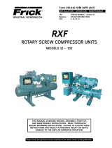
Figure 18. Slide Valve Potentiometers vs Linear Transmitters on Remanufactured XJF Compressors
SLIDE VALVE POTENTIOMETERS vs LINEAR TRANSMITTERS FOR RXF/RXB UNITS.
Remanufactured XJF compressors are supplied with a slide valve linear transmitter. The linear transmitter is used only with
the Quantum™ / Quantum™ LX microprocessor.
RXF/RXB Plus Microprocessors or Mini-micros:
If you are replacing an older compressor that has an RXF/RXB Plus microprocessor, or a Mini-micro, remove the slide valve
potentiometer assembly and indicator rod assembly (See Fig. 18a) prior to returning the compressor. Save these parts. Re-
move the linear transmitter (See Fig. 18c) from the remanufactured compressor. Replace it with your parts saved from the
original compressor.
It is recommended that you retain the old compressor until the new compressor is installed. However, if you have shipped the
original compressor back before removing the parts, and the unit does not have a Quantum™ / Quantum™ LX microprocessor,
you will need to order the following parts. (See Figure 18a):
Figure 18a.
Quantum™ Controls:
If the original unit has a Quantum™ / Quantum™ LX microprocessor with a slide valve potentiometer, the linear transmitter (See
Fig. 18c) on the remanufactured compressor may be used in place of the potentiometer. It will be necessary to install links
or jumpers (P/N 333Q0001419) at link location J14, J16, and pins 1 & 2 of J15 on the older style analog board (May 2003 and
earlier). If the Quantum™ has the current style analog board (June 2003 and later), this is done with a channel type selection
in Factory Setup. Contact your Frick® Factor for access and instruction. The linear transmitter needs to be set to 0-20 mA.
It will also be necessary to have a DIN connector (P/N 649A0890H01) and Gasket (P/N 649A0890H11) to connect the exist-
ing wire to the transmitter. Make sure the connector is wired as shown in publication S90-010 M Quantum™ Control Panel
Maintenance or 090-020 M Quantum™ LX Control Panel Maintenance for the RXF unit. (See Figure 18b).
Description XJF 95 XJF 120 XJF 151 Item
Slide Valve Potentiometer Service Kit 111Q0045464 111Q0045464 111Q0045464 1
Indicator Rod 534B0185H01 534B0235H01 534B0516H01 2
Indicator Rod Guide 534C0382H01 534C0382H01 534C1064H01 3
Spring 534A0148H01 534A0148H01 534A0148H01 4
O-ring (Internal) 980A0012A11 980A0012A11 980A0012A11 5
O-ring (External) 980A0012K62 980A0012K62 980A0012K62 6
Revised 2/25/2010

XJS/XJF COMPRESSOR REPLACEMENT
SERVICE MANUAL
070-660 SM (NOV 08)
Page 18
95 MM Compressors
RXB RXF 12-19
120 MM Compressors
RXB RXF 24 - 50
151 MM Compressors
RXF 58 - 101
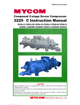
Figure 19. Installation of Precision Engineering Vi Control Valves and Gaskets, RXB & RXF Pkgs
Vi CONTROL VALVES AND GASKETS
Proper installation of the Vi control valves and
gaskets on XJS and XJF compressor models (RXB and
RXF packages) is essential to the operation of this
equipment. Incorrectly installed parts may cause the
compressor to operate at the wrong Vi, or to load or
unload improperly. Operation at the wrong compressor
Vi can cause excessive power consumption, noise,
vibration, or excessive oil foaming.
The following chart provides the logic of solenoid
valve operation to adjust the compressor volume ratio.
Solenoid valve #3 and #4 are referenced in the IOM
manuals as YY3 and YY4 or SV3 and SV4 respectively.
Figures 19 and 20 show the correct installation of gaskets
and valves. Note the “NO” (normally open) and “OUT”
(vent) labels on the solenoid valves. Position valves as
shown to insure proper operation of compressor.
NOTE: Valve positions are different on the different
compressor sizes.
Vi Solenoid Valve #3 Solenoid Valve #4
2.2 Energized Energized
3.5 De-Energized Energized
5 De-Energized De-Energized

XJS/XJF COMPRESSOR REPLACEMENT
SERVICE MANUAL
070-660 SM (NOV 08)
Page 19
Figure 20. Installation of Danfoss Vi Control Valves and Gaskets, RXB & RXF Pkgs
95 MM Compressors RXF 12 - 19
120 MM Compressors RXF 24 - 50
151 MM Compressors RXF 58 - 101

SGC COMPRESSOR REPLACEMENT
SERVICE MANUAL
070-660 SM (NOV 08)
Page 20
RWF MOTOR & COMPRESSOR REPLACEMENT PROCEDURE
The purpose of this procedure is to outline the process
for mounting replacement motors and compressors on
RWF packages in the eld. The goal is to ensure a stress-
free compressor and motor arrangement to assure the
designed life of the bearings and shaft seals. In addition,
a stress-free arrangement will yield proper slide valve
operation and minimize vibration.
Motor Replacement Procedure:
1. Verify that main power to the unit is disconnected.
Lockout and tag the switch.
2. Prior to removing the motor, the compressor must
be blocked up and properly supported. The entire
weight of the compressor and tunnel must be
supported. Reference Table 7 Compressor Weights.
Do not unbolt the compressor from the separator.
3. Remove the bolts between the motor and compressor
tunnel while supporting the motor weight. Then lift
the motor from the compressor package. Reference
Table 5. Motor Weights
4. Using a spring scale, weigh the replacement motor
prior to assembly to the compressor. Reference
Figure 22. If a spring scale is not available, contact
Frick or the motor manufacture for the weight of
the motor (Table 5 may also be used as a guide).
5. Align the D-ange or C-face motor holes to the
compressor tunnel holes while supporting the weight
of the motor.
6. Insert the bolts through the anged motor holes and
into the compressor tunnel and tighten by hand.
Figure 21. Weigh replacement motor Figure 22. Hydraulic piston supports motor weight
7. Continue to support the motor weight by maintaining
the same weight on the spring scale. If a spring scale
and/or overhead support is not available, then a
hydraulic piston may be used underneath the motor.
Reference Figure 22. (Contact the Baltimore Parts
Center for a Hydraulic Pump Kit, p/n 720A0029G01
- Ph:800-336-7264)
NOTE: The motor weight must be supported to avoid
stressing the compressor or motor. Do not over or
under support the motor. The scale or pressure gage
reading must be within +/- 10% of the motor weight.
8. If a hydraulic piston is used, then proceed with the
following guidelines:
a. Determine the area of the piston (Pressure = πr2)
or (Piston Area = Pi * Piston Diameter^2 / 4).
b. Calculate the required pressure (Pressure =
Weight of motor / Piston Area). The cylinder
manufacturer’s website will show a chart giving
the effective area.
c. Using a pressure gage between the hydraulic
piston and pump, increase the pressure until the
gage reaches the calculated required pressure.
9. Torque the bolts between the motor and compressor
tunnel to the required specication (Reference Table 6).
10. While the motor is still supported, shim any feet that
exhibit a gap (gauge reading + .002”). A pry or jack
can be used to lift the compressor .002”. Reinstall
and tighten bolts in feet. Then, bolt the motor to
the mounting base and torque the motor mounting
bolts to 250 ft-lb. Reference Figure 23.
11. The overhead support or hydraulic piston may now
be removed.
/