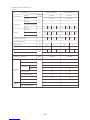
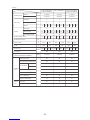
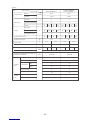
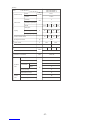
Mitsubishi Electric CITY MULTI PUHY-200YEM-A Service Handbook
- Category
- Split-system air conditioners
- Type
- Service Handbook
This manual is also suitable for

AIR CONDITIONERS CITY MULTI
Models PUHY-P200YEM-A, P250YEM-A, P315YEM-A
PUY-P200YEM-A, P250YEM-A, P315YEM-A
PURY-P200YEM-A, P250YEM-A
CMB-P104, P105, P106, P108, P1010, P1013, P1016V-F
PUHY-200YEM-A, 250YEM-A, 315YEM-A
PUY-200YEM-A, 250YEM-A, 315YEM-A
PUHY-250YEMK-A, 315YEMK-A
PUHY-200YEMC-A, 250YEMC-A, 315YEMC-A
Service Handbook

Contents
¡PRECAUTIONS FOR DEVICES THAT USE R407C REFRIGERANT .... 3
[1] Storage of Piping Material................................................................. 4
[2] Piping Machining............................................................................... 5
[3] Necessary Apparatus and Materials and Notes on Their Handling .. 6
[4] Brazing.............................................................................................. 7
[5] Airtightness Test................................................................................ 8
[6] Vacuuming ........................................................................................ 8
[7] Charging of Refrigerant..................................................................... 9
[8] Dryer ................................................................................................. 9
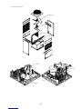
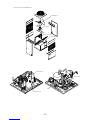
™COMPONENT OF EQUIPMENT ........................................................... 10
[1] Appearance of Components ........................................................... 10
[2] Refrigerant Circuit Diagram and Thermal Sensor........................... 19
[3] Electrical Wiring Diagram................................................................ 24
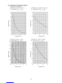
[4] Standard Operation Data ................................................................ 29
[5] Function of Dip SW and Rotary SW................................................ 38
£TEST RUN .............................................................................................43
[1] Before Test Run ..............................................................................43
[2] Test Run Method.............................................................................47
¢GROUPING REGISTRATION OF INDOOR UNITS WITH REMOTE
CONTROLLER....................................................................................... 48
∞CONTROL.............................................................................................. 54
[1] Control of Outdoor Unit ................................................................... 54
[2] Control of BC Controller.................................................................. 61
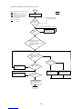
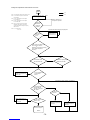
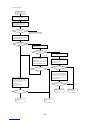
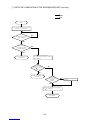
[3] Operation Flow Chart...................................................................... 62
[4] List of Major Component Functions ................................................ 68
[5] Resistance of Temperature Sensor................................................. 71
§REFRIGERANT AMOUNT ADJUSTMENT ............................................ 72
[1] Refrigerant Amount and Operating Characteristics ........................ 72
[3] Refrigerant Volume Adjustment Mode Operation ........................... 75
¶TROUBLESHOOTING ........................................................................... 80
[1] Principal Parts................................................................................. 80
[2] BC Controller Disassembly Procedure ..........................................
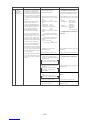
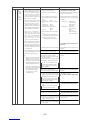
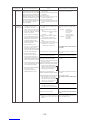
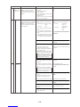
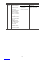
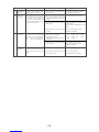
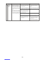
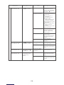
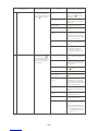
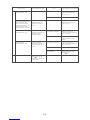
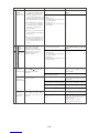
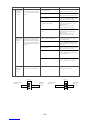
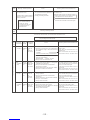
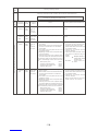
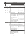
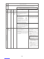
[3] Self-diagnosis and Countermeasures Depending on the Check
Code Displayed..............................................................................1
115
18
[4] LED Monitor Display ..................................................................... 143
•PREPARATION, REPAIRS AND REFRIGERANT REFILLING WHEN
REPAIRING LEAKS .............................................................................177
[3]
Location of leaks: Extension piping or indoor units (when cooling)177
[4] Location of leaks: Outdoor unit (when heating) ............................ 179
178
ªCHECK THE COMPOSITION OF THE REFRIGERANT
(R407 unit only) ......................................................................................180
[1]
[2] Location of leaks: Outdoor unit (Cooling mode)............................ 177
Location of leaks: Extension piping or indoor units
(Heating mode)
[2] Adjustment and Judgement of Refrigerant Amount ........................ 72
- 1 -

Safety precautions
Before installation and electric work
Before installing the unit, make sure you read all
the “Safety precautions”.
The “Safety precautions” provide very important
points regarding safety. Make sure you follow
them.
This equipment may not be applicable to
EN61000-3-2: 1995 and EN61000-3-3: 1995.
This equipment may have an adverse effect on
equipment on the same electrical supply system.
Please report to or take consent by the supply
authority before connection to the system.
Symbols used in the text
Warning:
Describes precautions that should be observed to
prevent danger of injury or death to the user.
Caution:
Describes precautions that should be observed to
prevent damage to the unit.
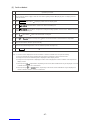
Symbols used in the illustrations
: Indicates an action that must be avoided.
: Indicates that important instructions must be followed.
: Indicates a part which must be grounded.
: Beware of electric shock (This symbol is displayed on the
main unit label.) <Color: Yellow>
Warning:
Carefully read the labels affixed to the main unit.
Warning:
• Use the specified cables for wiring. Make the connections
securely so that the outside force of the cable is not
applied to the terminals.
- Inadequate connection and fastening may generate heat and
cause a fire.
• Have all electric work done by a licensed electrician
according to “Electric Facility Engineering Standard” and
“Interior Wire Regulations”and the instructions given in
this manual and always use a special circuit.
- If the power source capacity is inadequate or electric work is
performed improperly, electric shock and fire may result.
• Securely install the cover of control box and the panel.
- If the cover and panel are not installed properly, dust or water
may enter the outdoor unit and fire or electric shock may
result.
• After completing service work, make sure that refrigerant
gas is not leaking.
- If the refrigerant gas leaks and is exposed to a fan heater,
stove, oven, or other heat source, it may generate noxious
gases.
• Do not reconstruct or change the settings of the protection
devices.
- If the pressure switch, thermal switch, or other protection
device is shorted and operated forcibly, or parts other than
those specified by Mitsubishi Electric are used, fire or
explosion may result.
- 2 -

¡PRECAUTIONS FOR DEVICES THAT USE R407C REFRIGERANT
Caution
Do not use the existing refrigerant piping.
• The old refrigerant and refrigerator oil in the existing
piping contains a large amount of chlorine which may
cause the refrigerator oil of the new unit to deterio-
rate.
Use refrigerant piping made of phosphorus deoxi-
dized copper and copper alloy seamless pipes and
tubes”. In addition, be sure that the inner and outer
surfaces of the pipes are clean and free of hazardous
sulphur, oxides, dust/dirt, shaving particles, oils,
moisture, or any other contaminant.
• Contaminants on the inside of the refrigerant piping
may cause the refrigerant residual oil to deteriorate.
Store the piping to be used during installation indoors
and keep both ends of the piping sealed until just
before brazing. (Store elbows and other joints in a
plastic bag.)
• If dust, dirt, or water enters the refrigerant cycle,
deterioration of the oil and compressor trouble may
result.
Use ester oil, ether oil or alkylbenzene (small
amount) as the refrigerator oil to coat flares and
flange connections.
• The refrigerator oil will degrade if it is mixed with a
large amount of mineral oil.
Use liquid refrigerant to seal the system.
• If gas refrigerant is used to seal the system, the com-
position of the refrigerant in the cylinder will change
and performance may drop.
Do not use a refrigerant other than R407C.
• If another refrigerant (R22, etc.) is used, the chlorine
in the refrigerant may cause the refrigerator oil to de-
teriorate.
Use a vacuum pump with a reverse flow check valve.
• The vacuum pump oil may flow back into the refriger-
ant cycle and cause the refrigerator oil to deteriorate.
Do not use the following tools that have been used
with conventional refrigerants.
(Gauge manifold, charge hose, gas leak detector, re-
verse flow check valve, refrigerant charge base,
vacuum gauge, refrigerant recovery equipment)
• If the conventional refrigerant and refrigerator oil are
mixed in the R407C, the refrigerant may deterio-
rated.
• If water is mixed in the R407C, the refrigerator oil
may deteriorate.
• Since R407C does not contain any chlorine, gas
leak detectors for conventional refrigerants will not
react to it.
Do not use a charging cylinder.
• Using a charging cylinder may cause the refrigerant
to deteriorate.
Be especially careful when managing the tools.
• If dust, dirt, or water gets in the refrigerant cycle, the
refrigerant may deteriorate.
If the refrigerant leaks, recover the refrigerant in the
refrigerant cycle, then recharge the cycle with the
specified amount of the liquid refrigerant indicated
on the air conditioner.
• Since R407C is a nonazeotropic refrigerant, if addi-
tionally charged when the refrigerant leaked, the com-
position of the refrigerant in the refrigerant cycle will
change and result in a drop in performance or abnor-
mal stopping.
- 3 -

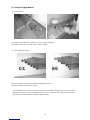
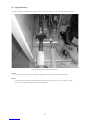
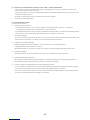
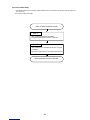
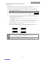
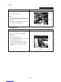
[1] Storage of Piping Material
(1) Storage location
Store the pipes to be used indoors. (Warehouse at site or owner’s warehouse)
Storing them outdoors may cause dirt, waste, or water to infiltrate.
(2) Pipe sealing before storage
Both ends of the pipes should be sealed until immediately before brazing.
Wrap elbows and T’s in plastic bags for storage.
✻The new refrigerator oil is 10 times more hygroscopic than the conventional refrigerator oil (such as Suniso). Water
infiltration in the refrigerant circuit may deteriorate the oil or cause a compressor failure. Piping materials must be
stored with more care than with the conventional refrigerant pipes.
OK
OK
NG
NG
- 4 -

[2] Piping Machining
Use ester oil, ether oil or alkylbenzene (small amount) as the refrigerator oil to coat flares and flange connections.
Use only the necessary minimum quantity of oil.
Reason :
1. The refrigerator oil used for the equipment is highly hygroscopic and may introduce water inside.
Notes :
•Introducing a great quantity of mineral oil into the refrigerant circuit may also cause a compressor failure.
•Do not use oils other than ester oil, ether oil or alkylbenzene.
- 5 -

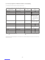
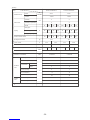
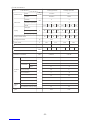
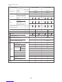
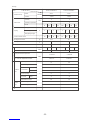
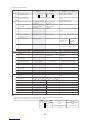
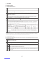
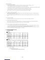
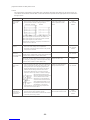
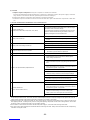
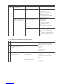
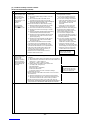
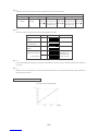
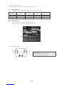
[3] Necessary Apparatus and Materials and Notes on Their Handling
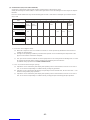
The following tools should be marked as dedicated tools for R407C.
<<Comparison of apparatus and materials used for R407C and for R22>>
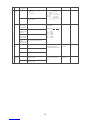
Apparatus Used Use R22 R407C
Gauge manifold Evacuating, refrigerant filling Current product
Charging hose Operation check Current product
Charging cylinder Refrigerant charging Current product Do not use.
Gas leakage detector Gas leakage check Current product Shared with R134a
Refrigerant collector Refrigerant collection R22 For R407C use only
Refrigerant cylinder Refrigerant filling R22
Vacuum pump Vacuum drying Current product
Vacuum pump with a check valve Current product
Flare tool Flaring of pipes Current product
Bender Bending of pipes Current product
Application oil Applied to flared parts Current product
Torque wrench Tightening of flare nuts Current product
Pipe cutter Cutting of pipes Current product
Welder and nitrogen cylinder Welding of pipes Current product
Refrigerant charging meter Refrigerant charging Current product
Vacuum gauge Checking the vacuum degree Current product
Symbols : To be used for R407C only. Can also be used for conventional refrigerants.
Tools for R407C must be handled with more care than those for conventional refrigerants. They must not come into contact
with any water or dirt.
Identification of dedi-
cated use for R407C
:Record refrigerant
name and put brown
belt on upper part of
cylinder.
Can be used by
attaching an adapter
with a check valve.
Ester oil or Ether oil or
Alkybenzene (Small
amount)
- 6 -

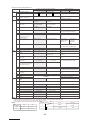
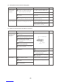
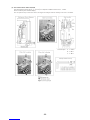
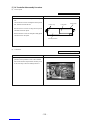
[4] Brazing
No changes from the conventional method, but special care is required so that foreign matter (ie. oxide scale, water, dirt,
etc.) does not enter the refrigerant circuit.
Example : Inner state of brazed section
When non-oxide brazing was not used When non-oxide brazing was used
Items to be strictly observed :
1. Do not conduct refrigerant piping work outdoors on a rainy day.
2. Apply non-oxide brazing.
3. Use a brazing material (BCuP-3) which requires no flux when brazing between copper pipes or between a copper pipe
and copper coupling.
4. If installed refrigerant pipes are not immediately connected to the equipment, then braze and seal both ends of them.
Reasons :
1. The new refrigerant oil is 10 times more hygroscopic than the conventional oil. The probability of a machine failure if
water infiltrates is higher than with conventional refrigerant oil.
2. A flux generally contains chlorine. A residual flux in the refrigerant circuit may generate sludge.
Note :
•Commercially available antioxidants may have adverse effects on the equipment due to its residue, etc. When
applying non-oxide brazing, use nitrogen.
- 7 -

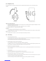
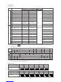
[5] Airtightness Test
No changes from the conventional method. Note that a refrigerant leakage detector for R22 cannot detect R407C
leakage.
Halide torch R22 leakage detector
Items to be strictly observed :
1. Pressurize the equipment with nitrogen up to the design pressure and then judge the equipment’s airtightness, taking
temperature variations into account.
2. When investigating leakage locations using a refrigerant, be sure to use R407C.
3. Ensure that R407C is in a liquid state when charging.
Reasons :
1. Use of oxygen as the pressurized gas may cause an explosion.
2. Charging with R407C gas will lead the composition of the remaining refrigerant in the cylinder to change and this
refrigerant can then not be used.
Note :
•A leakage detector for R407C is sold commercially and it should be purchased.
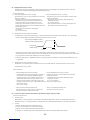
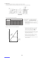
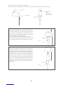
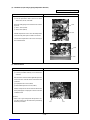
[6] Vacuuming
1. Vacuum pump with check valve
A vacuum pump with a check valve is required to prevent the vacuum pump oil from flowing back into the refrigerant
circuit when the vacuum pump power is turned off (power failure).
It is also possible to attach a check valve to the actual vacuum pump afterwards.
2. Standard degree of vacuum for the vacuum pump
Use a pump which reaches 65Pa or below after 5 minutes of operation.
In addition, be sure to use a vacuum pump that has been properly maintained and oiled using the specified oil. If the
vacuum pump is not properly maintained, the degree of vacuum may be too low.
3. Required accuracy of the vacuum gauge
Use a vacuum gauge that can measure up to 650Pa. Do not use a general gauge manifold since it cannot measure a
vacuum of 650Pa.
4. Evacuating time
•Evacuate the equipment for 1 hour after 650Pa has been reached.
•After envacuating, leave the equipment for 1 hour and make sure the that vacuum is not lost.
5. Operating procedure when the vacuum pump is stopped
In order to prevent a backflow of the vacuum pump oil, open the relief valve on the vacuum pump side or loosen the
charge hose to drawn in air before stopping operation.
The same operating procedure should be used when using a vacuum pump with a check valve.
NG NG
- 8 -

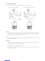
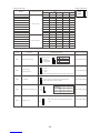
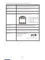
[7] Charging of Refrigerant
R407C must be in a liquid state when charging, because it is a non-azeotropic refrigerant.
For a cylinder with a syphon attached For a cylinder without a syphon attached
Cylinder color identification R407C-Gray Charged with liquid refrigerant
R410A-Pink
Reasons :
1. R407C is a mixture of 3 refrigerants, each with a different evaporation temperature. Therefore, if the equipment is
charged with R407C gas, then the refrigerant whose evaporation temperature is closest to the outside temperature is
charged first while the rest of refrigerants remain in the cylinder.
Note :
•In the case of a cylinder with a syphon, liquid R407C is charged without turning the cylinder up side down. Check the
type of cylinder before charging.
[8] Dryer
1. Replace the dryer when the refrigerant circuit is opened (Ex. Change the compressor, full gas leakage). Be sure to
replace the dryer with a CITY MULTI (For use with R407C).
If any other product is used, the unit will be damaged.
2. Opening the refrigerant circuit after changing to a new dryer is less than 1 hour. The replacement of the dryer should
be the last operation performed.
Cylin-
der
Cylin-
der
Valve Valve
Liquid Liquid
- 9 -


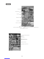
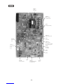
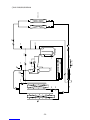
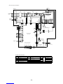
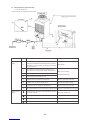
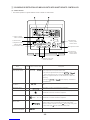
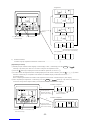
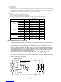
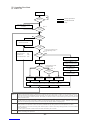
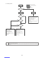
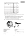
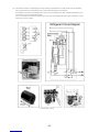
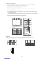
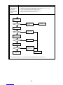
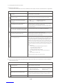
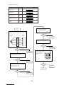
Controller Box
FANCON board
ACCT
INV board
MAIN board
Noise filter
Choke coil (L2)
Terminal block TB1A Power Source Terminal block TB7 Transmission (Centralized control)
Terminal block TB3 Transmission
Inteligent Power Module (IPM)
G/A board
DCCT
Diode stack (DS)
Magnetic contactor (52C)
Capacitor (C2, C3)
(Smoothing capacitor)
- 13 -

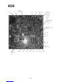
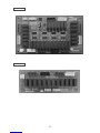
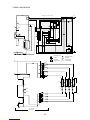
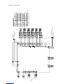
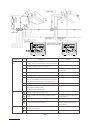
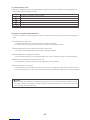
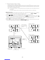
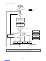
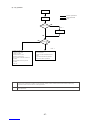
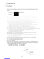
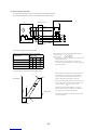
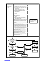
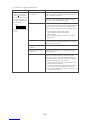
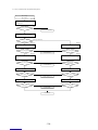
MAIN board
• PUHY / PURY
CN51
Indication distance
3-4 Compressor
ON/OFF
3-5 Trouble
CNRS3
Serial transmission to
INV board
CN3D
SW1
CNTR CNFC1
CNVCC4
Power source
for control(5V)
CN20
Power supply
3 L1
1 N
SW3
SW4 SW2 SWU2 SWU1
CNS1 CNS2 CN40 CN41 CNVCC3
Power Source
for control
1-2 30V
1-3 30V
4-6 12V
5-6 5V
CN3S
CN3N
LD1
Service LED
SWU3
CNTYP1
- 14 -

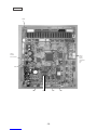
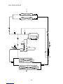
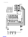
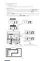
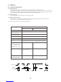
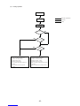
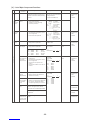
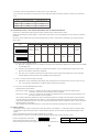
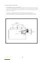
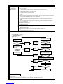
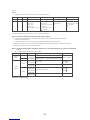
INV board
CNDR2
Out put to
G/A board
CNTH
CNCT
DCCT
CN15V2
Power supply
CNFG
Frame grounding
for IPM control
CNCT2
ACCT
CNAC2 I
Power source
1 L2
3 N
5 G
CN52AC
Control for
52C
CNRS2CN FAN
Control for MF1 Serial transmission
to MAIN board
SW1
CNVDC
1-4
DC-560V
CNVCC4
Power supply (5V)
CNL2
Choke coil
CNVCC2
Power supply
1-2 30V, 1-3 30V
4-6 12V, 5-6 5V
- 15 -


Page is loading ...
Page is loading ...
Page is loading ...
Page is loading ...
Page is loading ...
Page is loading ...
Page is loading ...
Page is loading ...
Page is loading ...
Page is loading ...
Page is loading ...
Page is loading ...
Page is loading ...
Page is loading ...
Page is loading ...
Page is loading ...
Page is loading ...
Page is loading ...
Page is loading ...
Page is loading ...
Page is loading ...
Page is loading ...
Page is loading ...
Page is loading ...
Page is loading ...
Page is loading ...
Page is loading ...
Page is loading ...
Page is loading ...
Page is loading ...
Page is loading ...
Page is loading ...
Page is loading ...
Page is loading ...
Page is loading ...
Page is loading ...
Page is loading ...
Page is loading ...
Page is loading ...
Page is loading ...
Page is loading ...
Page is loading ...
Page is loading ...
Page is loading ...
Page is loading ...
Page is loading ...
Page is loading ...
Page is loading ...
Page is loading ...
Page is loading ...
Page is loading ...
Page is loading ...
Page is loading ...
Page is loading ...
Page is loading ...
Page is loading ...
Page is loading ...
Page is loading ...
Page is loading ...
Page is loading ...
Page is loading ...
Page is loading ...
Page is loading ...
Page is loading ...
Page is loading ...
Page is loading ...
Page is loading ...
Page is loading ...
Page is loading ...
Page is loading ...
Page is loading ...
Page is loading ...
Page is loading ...
Page is loading ...
Page is loading ...
Page is loading ...
Page is loading ...
Page is loading ...
Page is loading ...
Page is loading ...
Page is loading ...
Page is loading ...
Page is loading ...
Page is loading ...
Page is loading ...
Page is loading ...
Page is loading ...
Page is loading ...
Page is loading ...
Page is loading ...
Page is loading ...
Page is loading ...
Page is loading ...
Page is loading ...
Page is loading ...
Page is loading ...
Page is loading ...
Page is loading ...
Page is loading ...
Page is loading ...
Page is loading ...
Page is loading ...
Page is loading ...
Page is loading ...
Page is loading ...
Page is loading ...
Page is loading ...
Page is loading ...
Page is loading ...
Page is loading ...
Page is loading ...
Page is loading ...
Page is loading ...
Page is loading ...
Page is loading ...
Page is loading ...
Page is loading ...
Page is loading ...
Page is loading ...
Page is loading ...
Page is loading ...
Page is loading ...
Page is loading ...
Page is loading ...
Page is loading ...
Page is loading ...
Page is loading ...
Page is loading ...
Page is loading ...
Page is loading ...
Page is loading ...
Page is loading ...
Page is loading ...
Page is loading ...
Page is loading ...
Page is loading ...
Page is loading ...
Page is loading ...
Page is loading ...
Page is loading ...
Page is loading ...
Page is loading ...
Page is loading ...
Page is loading ...
Page is loading ...
Page is loading ...
Page is loading ...
Page is loading ...
Page is loading ...
Page is loading ...
Page is loading ...
Page is loading ...
Page is loading ...
Page is loading ...
Page is loading ...
Page is loading ...
Page is loading ...
Page is loading ...
Page is loading ...
Page is loading ...
Page is loading ...
Page is loading ...
Page is loading ...
-
 1
1
-
 2
2
-
 3
3
-
 4
4
-
 5
5
-
 6
6
-
 7
7
-
 8
8
-
 9
9
-
 10
10
-
 11
11
-
 12
12
-
 13
13
-
 14
14
-
 15
15
-
 16
16
-
 17
17
-
 18
18
-
 19
19
-
 20
20
-
 21
21
-
 22
22
-
 23
23
-
 24
24
-
 25
25
-
 26
26
-
 27
27
-
 28
28
-
 29
29
-
 30
30
-
 31
31
-
 32
32
-
 33
33
-
 34
34
-
 35
35
-
 36
36
-
 37
37
-
 38
38
-
 39
39
-
 40
40
-
 41
41
-
 42
42
-
 43
43
-
 44
44
-
 45
45
-
 46
46
-
 47
47
-
 48
48
-
 49
49
-
 50
50
-
 51
51
-
 52
52
-
 53
53
-
 54
54
-
 55
55
-
 56
56
-
 57
57
-
 58
58
-
 59
59
-
 60
60
-
 61
61
-
 62
62
-
 63
63
-
 64
64
-
 65
65
-
 66
66
-
 67
67
-
 68
68
-
 69
69
-
 70
70
-
 71
71
-
 72
72
-
 73
73
-
 74
74
-
 75
75
-
 76
76
-
 77
77
-
 78
78
-
 79
79
-
 80
80
-
 81
81
-
 82
82
-
 83
83
-
 84
84
-
 85
85
-
 86
86
-
 87
87
-
 88
88
-
 89
89
-
 90
90
-
 91
91
-
 92
92
-
 93
93
-
 94
94
-
 95
95
-
 96
96
-
 97
97
-
 98
98
-
 99
99
-
 100
100
-
 101
101
-
 102
102
-
 103
103
-
 104
104
-
 105
105
-
 106
106
-
 107
107
-
 108
108
-
 109
109
-
 110
110
-
 111
111
-
 112
112
-
 113
113
-
 114
114
-
 115
115
-
 116
116
-
 117
117
-
 118
118
-
 119
119
-
 120
120
-
 121
121
-
 122
122
-
 123
123
-
 124
124
-
 125
125
-
 126
126
-
 127
127
-
 128
128
-
 129
129
-
 130
130
-
 131
131
-
 132
132
-
 133
133
-
 134
134
-
 135
135
-
 136
136
-
 137
137
-
 138
138
-
 139
139
-
 140
140
-
 141
141
-
 142
142
-
 143
143
-
 144
144
-
 145
145
-
 146
146
-
 147
147
-
 148
148
-
 149
149
-
 150
150
-
 151
151
-
 152
152
-
 153
153
-
 154
154
-
 155
155
-
 156
156
-
 157
157
-
 158
158
-
 159
159
-
 160
160
-
 161
161
-
 162
162
-
 163
163
-
 164
164
-
 165
165
-
 166
166
-
 167
167
-
 168
168
-
 169
169
-
 170
170
-
 171
171
-
 172
172
-
 173
173
-
 174
174
-
 175
175
-
 176
176
-
 177
177
-
 178
178
-
 179
179
-
 180
180
-
 181
181
-
 182
182
-
 183
183


Mitsubishi Electric CITY MULTI PUHY-200YEM-A Service Handbook
- Category
- Split-system air conditioners
- Type
- Service Handbook
- This manual is also suitable for
Ask a question and I''ll find the answer in the document
Finding information in a document is now easier with AI
Related papers
-
Mitsubishi Electric CMB-P104 Service Handbook
-
-
-
Mitsubishi P96 User manual
-
-
-
Mitsubishi Electric MXZ-8C48NA2 Owner's manual
-
-
-
Mitsubishi Electric PFFY-W-VCM-A User manual
Other documents
-
-
Tecno LD7 User manual
-
Code Electronic PUY-A42NHA2-BS User manual
-
Velleman K8028 User manual
-
Sanyo SPW-C1503GDYH8 Technical Data & Service Manual
-
-
McQuay MDS030A Installation guide
-
Argo AE2MI56AH User manual
-
Portfolio LD4 User manual
-