Page is loading ...

Model: PLUS-4900
Installation
Manual
For Technical Assistance, please call (800) 638-3600,
or visit www.magnadyne.com
This device complies with part 15 of the FCC rules. Operation is subject to the following two conditions:
(1) This device may not cause harmful interference; and
(2) This device must accept any interference received, including interference that may cause undesired operation.
Note: The manufacturer is not responsible for any radio or TV interference caused by unauthorized modifications
to this equipment. Such modifications could void the user’s authority to operate the equipment.
R
Automotive Security
PLUS-4900-IM.qxp 4/30/09 3:06 PM Page 1

2
Component Installation . . . . . . . . . . . . . . . . . . . . . . . . . . . . . . . . . . . . . . . . . . . . . . . . . . . . . . . . . . . . . 2
10-Pin Main Harness Installation . . . . . . . . . . . . . . . . . . . . . . . . . . . . . . . . . . . . . . . . . . . . . . . . . . . . . 3
5-Pin Power Harness Installation . . . . . . . . . . . . . . . . . . . . . . . . . . . . . . . . . . . . . . . . . . . . . . . . . . . . . . 4
LED, Valet Switch Connection . . . . . . . . . . . . . . . . . . . . . . . . . . . . . . . . . . . . . . . . . . . . . . . . . . . . . . . . 5
Door Lock Connections . . . . . . . . . . . . . . . . . . . . . . . . . . . . . . . . . . . . . . . . . . . . . . . . . . . . . . . . . . . . 6-8
Optional Accessory Connections . . . . . . . . . . . . . . . . . . . . . . . . . . . . . . . . . . . . . . . . . . . . . . . . . . . . 9-10
Transmitter Programming . . . . . . . . . . . . . . . . . . . . . . . . . . . . . . . . . . . . . . . . . . . . . . . . . . . . . . . . . . 11
Alarm Feature Programming . . . . . . . . . . . . . . . . . . . . . . . . . . . . . . . . . . . . . . . . . . . . . . . . . . . . . . 11-13
Internal and External Sensor Testing and Adjustment . . . . . . . . . . . . . . . . . . . . . . . . . . . . . . . . . . . . . 14
Reference Wiring Diagram . . . . . . . . . . . . . . . . . . . . . . . . . . . . . . . . . . . . . . . . . . . . . . . . . . . . . . . . 15
Mounting the Control Module:
Find a suitable location to secure the alarm control module within the passengers compartment of the vehicle.
Never mount the alarm control module in the engine compartment or in the trunk. In addition, never mount the
alarm control module in the direct path of the heater. Secure the alarm control module by using wire ties or drill
two 1/8" holes and secure the module to the frame of the vehicle with the screws provided.
Installing Hood / Trunk Pin Switches:
Provided with the alarm kit is one pin switch and one mounting bracket. To install the switch either in the truck
or under the hood, find a suitable location where the switch will make contact with the hood or trunk lid and will
not get wet. Use the bracket provided or drill a 1/4" hole in the desired location.
Mounting the Siren:
Find a suitable mounting location in the engine compartment to secure the siren. Select a location that provides
a direct sound path to the ground for maximum siren effect. Use the self-tapping screws to secure the siren.
Connect the Black wire from the siren to the frame of the vehicle. In many cases, you can connect the Black wire
to one of the siren mounting screws. Run the remaining brown wire from the siren through a grommet in the
vehicle firewall to the location of the alarm control module.
Valet Switch
Select a mounting location for the switch that is easily accessible to the driver of the vehicle. The switch does
not have to be concealed. However, concealing the switch is always recommended, as this provides an even
higher level of security to the vehicle. Mount the valet switch in a hidden but accessible location. Route the valet
switch wires to the control module.
LED Status Indicator
The LED status indicator should be mounted in a highly visible area. Their should be at least 6mm of space
behind the mounting location for LED housing. Once a suitable location is chosen, drill a 1/4" hole. Run the LED
wires through the hole then press the LED housing into the place. Route the LED wires to the control module.
Warning! Do not plug the 10-pin or 5-pin wire harness into the alarm control module before you
begin installing the alarm. The wire harnesses must be plugged into the alarm control module after all
connections are made. Failure to follow this procedure could cause some confusion with transmitter
operation and or alarm function operation.
Contents
Component Installation
PLUS-4900-IM.qxp 4/30/09 3:06 PM Page 2

3
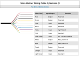
The main wire harness contains 8 wires which all have a specific purpose. Follow the wiring recommendations
enclosed for each wire. Wires not used should be released from the harness connector or taped off to prevent
accidental shorting.
HC4
10-Pin Main Harness
Light Brown (-) Horn Output
Green (-) Common Door Pin Input
Violet (+) Common Door Pin Input
Blue (-) Hood / Trunk / Auxiliary Trigger Input
Red/White
(-) 300mA Programmable Channel 3 (Trunk) Output
White (+/-) Parking Light Relay Output
Brown (+) Siren Output
White/Fused (+/-) Parking Light Relay Input
Open No Connection
Open Provides +12VDC for Relay Connection
Light Brown Wire: (Pulsed Ground for Car Horn)
The light brown wire is a pulsed ground output designed to activate the vehicle’s existing car horn system in
place of or in addition to a siren sounding device. Connect the light brown wire to the negative trigger wire on
the vehicle’s horn relay.
WARNING! Maximum output of this wire is 300mA. Horn systems requiring positive voltage or more than
300mA to trigger the horn relay will require an additional relay to increase current capabilities.
White 10-Pin Connector
87
87a
86
85
30
Light Brown Wire
To +12V
To Horn
+12V or Ground Depending
on System Requirements
Fuse
Brown Wire: (Siren + Output)
Connect the brown wire to the positive wire from a siren. Ground the remaining wire from the siren for proper
operation.
Blue Wire: (Optional Grounding Sensor Input)
The blue wire is an instant grounding trigger input for optional hood/trunk grounded pin switches or any
electronic sensor.
Green Wire: (Grounded Door Pin Switch Input)
The green wire connects to the common wire of the vehicle that switches on the dome light. Normally this wire is
located at one of the door jamb switches. For some vehicles it may be necessary to connect the green wire directly
to the switched turn on wire at the dome light. The green wire connects to negative switched circuits only.
Wiring
PLUS-4900-IM.qxp 4/30/09 3:06 PM Page 3

4
White 5-Pin Connector
HC2 5 Pin Power Harness
Black/White (-) Dome Light Supervision Output
Black Chassis Ground
Yellow +12VDC Ignition Input
Open Provides +12VDC for Relay Connection
Red +12VDC Battery Input
White 10-Pin Connector (Continued)
Violet Wire: (Positive Door Pin Switch Input)
The violet wire connects to the common wire of the vehicle that switches on the dome light. Normally this wire is
located at one of the door jamb switches. For some vehicles it may be necessary to connect the violet wire directly
to the switched turn on wire at the dome light. The violet wire connects to positive switched circuits only.
Red/White Wire: (-) 200mA Programmable Channel 3 Output
(See Alarm Feature Programming Part 3) (Factory default setting on momentary ground) This wire is built-in
user programmable timer output provides a ground through this wire. You may program the built-in timer to
send ground signal for any time interval between 1 second and 2 minutes. For instance, this timer output may
be used to turn on the headlights with the remote control. Also, on certain Mercedes Benz, BMW, Jaguar and
Volkswagens you can use this unique timed output to allow remote closure of all power windows and sunroof
without the need for an external module.
White: (Pulsed Parking Light Relay Output)
Connect the white wire to the parking light wire coming from the headlight switch. Do not connect the white
wire to the dashboard lighting dimmer switch – Damage to the dimmer will result. Use a volt meter to test the
connection point before connecting the red/white wire. While checking, rotate the dimmer switch to make sure
you do not have the dimmer lead. The limitation of the white wire is 10 Amp max. Do not exceed this limit or
damage to the alarm and parking light relay will result.
Parking
Lights
Only
Piggyback
Connection
Headlight Switch
White Wire
White W/ Fuse: (Parking Light Relay Input)
The White w/fuse wire is the input to the flashing parking light relay. The connection of this wire will determine
the output polarity of the flashing parking light relay. Connect the White wire w/ fuse wire to (+) battery to have
(+) output from the relay or connect the white wire to frame ground to have ground output from the relay.
Wiring
(Continued)
PLUS-4900-IM.qxp 4/30/09 3:06 PM Page 4

5
Black/White Wire: (Programmable Output. Default Setting Domelight Supervision )
The Black/White wire is a low current (300mA) grounded output wire that is pre-programmed to activate the
vehicle’s interior lighting system when the security system is disarmed. An additional relay may be required for
proper installation (See Optional Accessory Connection for proper wiring). This wire can also be programmed to
operate as a channel #4 output (See Alarm Feature Programming Part 2 for programming instructions)
Red Wire: (Main Power Input)
Connect the red wire directly to the (+) battery post for best operation of the alarm system. For best current
sensing capability from the alarm’s current sensing circuit, connect the red wire to the constant power wire
coming from the interior dome light.
Black Wire: (Main Ground Input)
Connect the black wire directly to the frame of the vehicle. Use a bolt and nut to secure the wire. Scrape away
any grease or paint that might prevent a good connection.
Yellow Wire: (Switched +12 Volts From the Ignition Switch)
Connect the yellow wire to a +12 volt wire that is switched on and off by the ignition key. The correct wire will
indicate +12 volts when the ignition key is in the on and start positions. Do not connect the yellow wire to the
“ACC” wire coming from the ignition switch.
White 5-Pin Connector (Continued)
White 2-Pin Connector
LED Status Indicator:
The LED indicator status should be mounted in a highly visible area such as top of the dashboard, on top of
the shifter console or on dashboard face. Leave at least 6mm space behind the mounting location for LED
housing. Once a suitable location is chosen, drill a 1/4” hole. Run the LED wires though the hole then press
the LED housing into the place. Route the LED wires to the control module.
Blue 2-Pin Connector
Valet Switch
Select a mounting location for the switch that is easily accessible to the driver of the vehicle. The switch does
not have to be concealed, however, concealing the switch is always recommended, as this provides an even
higher level of security to the vehicle. Mount the valet switch in a hidden but accessible location. Route the
valet switch wires to the control module.
Wiring
(Continued)
PLUS-4900-IM.qxp 4/30/09 3:06 PM Page 5

6
3 Wire Positive Trigger Door Lock System
(+) Lock Out
+12 Volts Input
(+) Unlock Out
To Door Lock
Control Relays
Blue Wire: Connect to Unlock
Green Wire: Connect to Lock
Lock Control
Switch
Black 3-Pin
Mini Connector
87
87A
85
86
30
87
87A
85
86
30
To Fused +12v
Black 3-Pin Connector
3 Wire Ground Trigger Door Lock System
(
-
) Lock Out
Ground Input
(
-
) Unlock Out
To Door Lock
Control Relays
Lock Control
Switch
Blue Wire: Connect to Unlock
Green Wire: Connect to Lock
Black 3-Pin
Mini Connector
Unlock Driver's Door First for 3-Wire Negative Door Lock Systems
87
87A
85
86
30
Unlock Wire
Passenger's Door
Lock
Unlock
To +12V or Ground
To +12V or Ground
Driver's Door
Rear Doors
Passenger's
Door Switch
Door Lock Relay
Control Module
Lock
Unlock
+12V
ALA984H
Relay
Driver's Door
Switch
Cut
Blue Wire
Green Wire
Light Blue Wire
Wiring
(Continued)
PLUS-4900-IM.qxp 4/30/09 3:06 PM Page 6

7
5 Wire Ground at Rest Door Locking Systems
87
87A
85
86
30
87
87A
85
86
30
To +12 Volts
(Battery +)
To Power
Lock Switch
To Power
Lock Motors
White Wire: Lock
Brown Wire: Unlock
Green Wire: Lock
Blue Wire: Unlock
Violet Wire
ALA-DL1
Relay Pack
Red Wire: Lock
Black Wire: Unlock
Black 3-Pin
Connector
Green Wire
Blue Wire
Note 1: Orange wire (Not Shown)
from ALA-DL1must be connected
to +12V
Note 2:
For bulk relay usage, wiring
shown still applies
Black 3-Pin Connector (Continued)
Unlock Driver's Door First Wiring for 3-Wire Positive Door Locking Systems
87
87A
85
86
30
87
87A
85
86
30
To +12 Volts
(Battery +)
To Power
Door Lock
Switch
Lock/Unlock
Wires
Lock
Unlock
87
87A
85
86
30
+ Unlock
Cut
Driver's
Door
Motor
Blue Wire
Green Wire
Light Blue Wire
Unlock Driver's Door First Wiring for 5-Wire Ground at Rest Door Locking Systems
87
87A
85
86
30
87
87A
85
86
30
To +12 Volts
(Battery +)
To Power
Lock Switch
To Power
Lock Motors
Lock
Lock
Unlock
Unlock
87
87A
85
86
30
+ Unlock
Cut
Driver's
Door Motor
Green Wire
Blue Wire
Light Blue Wire
Wiring
(Continued)
PLUS-4900-IM.qxp 4/30/09 3:06 PM Page 7

8
Black 3-Pin Mini Connector (Continued)
One Wire Multiplexing Door Locking Systems
Some vehicles (Chrysler, Mazda and others) use one wire to lock and unlock the doors. Example: When
the door lock controller sees a signal thru a resistor it will unlock. If a signal is received without a resistor
the doors will lock. Some use 2 resistors. One for lock and one for unlock. We have developed patented
plug-in fuse resistors for this application. Simply remove the fuse from our door lock module and replace
with correct resistor value fuses that matches the vehicles door lock switch.
ALA-DL1 Wiring:
1. Connect both the green (lock) and the blue (unlock) wires to the vehicles one wire lock/unlock wire.
2. Connect our violet polarity input wire to +12V or to ground. To match vehicles door lock polarity.
3. The white and the brown wires will not be used.
White Wire: No Connection
Brown Wire: No Connection
Green Wire:
Blue Wire:
Violet Wire To +12 Volts Constant
Lock Fuse 1
Unlock Fuse 2
ALA-DL1
Red Wire
Black Wire
Black 3-Pin
Connector
Green Wire
Blue Wire
Note: Orange wire (Not Shown) from ALA-DL1 must be connected to +12V.
To Vehicles
Lock/Unlock Wire
Mercedes Door Lock Activation
Door Lock
Switch
Unlock
Lock
B+
87
87A
85
86
30
87
87A
85
86
+
++
To +12 Volts
(Battery +)
Door Lock
Compressor
Cut
Green Wire
Unlock
Lock
Black 3-Pin
Connector
Green Wire: Lock
Blue Wire: Unlock
Newly Installed Power Door Lock Motors
87
87A
85
86
30
87
87A
85
86
30
To +12 Volts
(Battery +)
To Ground
To Newly
Installed Power
Door Lock Motors
White Wire
Brown Wire
Green Wire: Lock
Blue Wire: Unlock
Violet Wire
ALA-DL1
Relay Pack
Red Wire: Lock
Black Wire: Unlock
Black 3-Pin
Connector
Green Wire
Blue Wire
Note: Orange wire from ALA-DL1
(Not Shown) must be connected
to +12V
Wiring
(Continued)
PLUS-4900-IM.qxp 4/30/09 3:06 PM Page 8

9
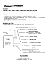
Starter Disable Wiring Using a Common Relay
Using the wiring information and diagram below, connect the optional starter disable relay as follows:
A. Locate the “Start Only Wire” coming from the ignition key switch and cut it.
B. Connect the ends of the cut start wire to pins #30 and 87a of the relay pack.
C. Connect the single gray wire harness supplied (with 2-pin black connector) to pin #85 on the relay.
D. Connect pin #86 to the true ignition switched wire from the ignition key.
To test the starter disable system refer to the starter disable testing procedures located in the testing section of
this manual.
Orange 2-Pin Mini Port
Orange Wire
(Ground when Armed Alarm Output)
2-Pin Orange
Connector
(Supplied)
87
87a
86
85
30
"ACC" "START"
"OFF" "IGN"
Cut BlackBlack
Starter
Starter Disable Wiring Using ALA-RPS Relay Pack
Using the wiring information and diagram below, connect the optional starter disable relay as follows:
A. Locate the “Start Only Wire” coming from the ignition key switch and cut it.
B. Connect the ends of the cut start wire to the black wires coming from the ALA-RPS relay pack.
C. Plug in the orange 2-pin plug into the orange socket located at the rear of alarm module.
To test the starter disable system refer to the starter disable testing procedures located in the testing section of
this manual.
87
87a
86
85
30
"ACC" "START"
"OFF" "ON"
Cut Black
Starter
ALA-RPS
Relay Pack
Red Wire
(Ign. Switched +12VDC)
Black Wire
(Ground when Armed Alarm Output)
Black
Optional Accessory Connections
PLUS-4900-IM.qxp 4/30/09 3:06 PM Page 9

10
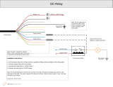
Dome Light Supervision Using Optional ALA-RPT Relay Pack:
Red Wire
ALA-RPT
Relay Pack
Orange Wire
Output to Dome Light (+ or
-
)
Purple Wire
Input to Relay (+ or
-
)
Insert Black Wire into the First Socket
Insert Red Wire into the Second Socket
Black Wire
87
86
85
30
Red/White Wire
(SPST ALA984H
Relay Not Supplied)
Output to Power Trunk Switch
To Constant +12 Volts
Input to Relay (+ or
-
)
Power Trunk Activation Using Optional 30 Amp Relay
Red Wire
ALA-RPT
Relay Pack
Orange Wire
Output to Trunk Switch
Purple Wire
Input to Relay (+ or
-
)
Insert Red Wire into the First Socket
Insert Black Wire into the Eighth Socket
Black Wire
Power Trunk Activation Using Optional ALA-RPT Relay Pack
Dome Light Supervision Using Optional 30 Amp Relay:
87
86
85
30
Black/White Wire
(SPST ALA984H
Relay Not Supplied)
Output to Dome Light (+ or
-
)
To Constant +12 Volts
Input to Relay (+ or
-
)
Channel 4 Output Using 30 Amp Relay: (Valid Only when Black/White Wire is Programmed for CH#4 Output)
87
86
85
30
Black/White Wire
(SPST ALA984H
Relay Not Supplied)
Output (+ or
-
)
To Constant +12 Volts
Input to Relay (+ or
-
)
Optional Accessory Connection
(Continued)
PLUS-4900-IM.qxp 4/30/09 3:06 PM Page 10

11
Turn the ignition switch from the OFF position to the
ON position.
ON
ON
Programming the Remote Transmitter
Note: This mode will only retain the last 4 remote transmitters programmed. If the transmitter memory is
exceeded, the security system will start deleting transmitters from memory in chronological order.
Before 15 seconds has passed, push and release the valet
switch 3 times. You will hear a single chirp from the
siren/horn. You are now in transmitter programming
mode.
3X
Press the “Lock” button on the first
transmitter until you hear a
confirmation chirp/beep. The
transmitter is now programmed to
the control module.
Repeat step 3 for each additional
transmitter.
When finished, either turn off the
ignition key or wait for 15 seconds to
get out of transmitter programming
mode. You will hear 1 short + 1 long
chirps/beeps to indicate you are out of
the transmitter programming mode.
OFF
Examine the 3 different feature charts enclosed and decide which feature will get changed. Circling the feature to
be changed will make the programming process much easier to perform.
Turn the ignition switch from the OFF position to the
ON position 3 times leaving it in the OFF position the
third time.
OFF
ON
3X
Before 15 seconds has passed, push and release the
valet switch 1 time then push the valet switch a second
time and hold it down until 1 short and 1 long chirp or
beep is heard, then release it. You are now in Alarm
Feature Programming Part 1 programming mode
1X + 1X (Hold)
Programming the Transmitter
Step 1
Step 2
Step 3
Step 1
Step 2
Alarm Feature Programming (Part 1)
Step 4
Step 5
PLUS-4900-IM.qxp 4/30/09 3:06 PM Page 11

One Chirp Two Chirps Three Chirps Four Chirps
Button LED One Pulse LED Two Pulses LED Three Pulses LED Four Pulses
(Factory Default Setting)
12
ON
Turn On the Ignition
3 long chirps and 3 flashes of the parking lights will
confirm exit of the programming mode.
Note: Waiting 15 seconds after the last command will
also cause the system to automatically exit the
programming mode.
Remote Feature Programming
Use the transmitter buttons as illustrated to adjust the features required. Keep repressing the transmitter button
that relates to the feature you want to adjust until the correct amount of chirps/beeps is heard. Move on to the
next feature.
Chirps On, All Outputs Chirps Siren Output Only Chirps Horn Output Only Arm/Disarm Chirps Off
Automatic Arming without
Passive Door Locking
Automatic Arming with
Passive Door Locking
Manual Arming
Automatic Rearm Off Automatic Rearm On
Instant Door Ajar Warning
45 Seconds Delay
Door Ajar Warning
Car-Jack Mode Off
Manual Car-Jack Mode
+
Automatic Car
Jack Mode
Door Ajar Warning Off
*Instant / 45 Seconds Delay Door Ajar Warning
This feature controls the error chirp that is generated if the system is armed with the door trigger active. This is
useful in a vehicle that has a long dome light delays after the door has been closed. If the system is armed before
the dome light has turned off, the security system will generate the door trigger error chirp. Use this feature to
disable the door open error chirp.
Parking Light “On” for
30 Seconds Upon an
Unlock Signal
Pathway Illumination
Feature “Off”
Parking Light “On” for 30
Seconds Upon an Unlock
Signal and 10 Second Upon
a Lock Signal
+
+
Ignition Key Controlled
Door Lock Only
Ignition Key Controlled
Door Unlock Only
Ignition Key Controlled
Door Lock and Unlock On
Ignition Key Controlled
Door
Lock and Unlock Off
Alarm Feature Programming (Part 1 )
Step 3
Step 4
(Continued)
PLUS-4900-IM.qxp 4/30/09 3:06 PM Page 12

13
Turn the ignition switch from the OFF position to the
ON position 3 times leaving it in the OFF position the
third time.
OFF
ON
3X
Remote Feature Programming
Use the transmitter buttons as illustrated to adjust the features required. Keep repressing the transmitter button that
relates to the feature you want to adjust until the correct amount of chirps/beeps is heard. Move on to the next feature.
One Chirp / Two Chirps / Three Chirps / Four Chirps /
Button LED One Pulse LED Two Pulse LED Three Pulse LED Four Pulse
(Factory Default Setting)
0.8 Second
Door Lock Pulses
0.6 Second
Door Lock Pulses
3.5 Second
Door Lock Pulse
Door Lock with
“Comfort Feature”
See Note Below
ON
Turn On the Ignition
3 long chirps and 3 flashes of the
parking lights will confirm exit of
the programming mode.
Note: Waiting 15 seconds after the
last command will also cause the
system to automatically exit the
programming mode.
Comfort Feature:
Some vehicles have a special “Comfort Feature”. When you lock the door with the key, you have to hold the key in the
lock position for about 5 to 7 seconds and the windows will close automatically. If you wish the vehicle’s Comfort
Feature to be activated when you remotely lock the doors, program
Door Lock with Comfort Feature
“
ON”
.
5 Chirps = 0.8 Second Double Pulse Unlock
6 Chirps = 0.6 Second Double Pulse Unlock
3X + 1X (Hold)
Before 15 seconds has passed, push and release the
valet switch 3 times then push the valet switch a fourth
time and hold it down until 2 short chirps/beeps + 1
long chirp/beep is heard then release it. You are now in
Part 2 programming mode.
Channel #3 Output is
Single Pulse
Channel #3 Output is
Latched Until the Ignition
Key is On
Channel # 3 Output is On
for 15 Seconds then is Off
Channel # 3 Output is On
for 30 Seconds then is Off
Light Blue Wire Has (-) 2nd
Unlock Output Function
Light Blue Wire has (-)
Factory Alarm Disarm Output
Function
Black/White Wire has (-)
Domelight Supervision
Output
Black/White Wire has (-)
Channel #4 Single Pulse
Output
Step 1
Step 2
Alarm Feature Programming (Part 2)
Step 3
Step 4
PLUS-4900-IM.qxp 4/30/09 3:06 PM Page 13

Turn the ignition switch from the OFF position to the ON position 4 times leaving it in the OFF position the fourth
time. The Horn/Siren will beep (1) time. You are now in “On-Board Shock Sensor Adjustment Mode”.
ON
OFF
4X
ON
OFF
5X
Turn the ignition switch from the OFF position to the ON position 5 times leaving it in the OFF position the fifth
time. The Horn/Siren will beep (2) times. You are now in “External Sensor Adjustment Mode”.
On-Board Shock Sensor Only:
Follow steps 1 thru 3 to make sensitivity adjustments to the On-Board Shock Sensor
On-Board Shock Sensor and Optional 2nd Sensor Installations:
If the installation is using (2) sensors, follow steps 1 thru 3 under “2nd Sensor Adjustment” to make sensitivity
adjustments to the 2nd sensor.
ON
1. Light impacts to the body and glass will trigger the
“pre-warning indicator”. The horn/siren will chirp 3
times. Hard impacts to the body or glass will trigger
the “Full Trigger Indicator” . The horn/siren will chirp
1time.
2. Rotate the sensitivity adjuster “Clockwise” to
increase the impact sensitivity.
3. Rotate the sensitivity adjuster “Counterclockwise”
to decrease the impact sensitivity.
Turn the ignition switch from the OFF position to the
ON position to exit the sensor adjustment mode. The
horn/siren will chirp 3 short chirps and 1 longer chirp.
You have exited “On-Board Sensor Adjustment Mode”.
14
Step 1
Step 1
On-Board Shock & Optional 2nd Sensor Sensitivity Adjustment
On-Board Sensor Adjustment
Optional 2nd Sensor Adjustment
Step 2
Step 3
Step 2
Step 3
PLUS-4900-IM.qxp 4/30/09 3:06 PM Page 14

15
5-Pin
White
10-Pin
White
2-Pin
Orange
Black Wire Ground to Vehicle Frame
Yellow Wire to Ignition Switched +12 V
Red Wire To Battery+ 12V Input
Light Brown Wire Horn Output
Brown Wire Siren Output (+)
Blue Wire Negative AUX Trigger Input
Violet Wire Positive Door Pin Trigger Input
White Wire Parking LightsRelayOutput
10A
White Wire Parking LightsRelay Input
Green Wire Negative Door Pin Trigger Input
Programmable Channel 3 Ouput (Trunk)
5A
Starter Disable Port (See Optional AccessoryConnection)
2-Pin
White
LED Indicator
Valet Switch
Green Wire: Warn Away Ground Trigger
Blue Wire: Zone 4 Ground Trigger
Black Wire: Negative Power
Red Wire: +12V Power
Green Wire : (-) LockPulse - (+) Unlock Pulse
Blue Wire : (-) UnlockPulse - (+) Lock Pulse
Light Blue Wire :
(-) Programmable Output (Default 2nd Unlock)
2-Pin
Blue
4-Pin
White
3-Pin
Black
PLUS 4900 Wiring Diagram
Red/WhiteWire
(-) Programmable Output (Default Domelight Supervision)
Black/WhiteWire
Orange Wire:Ground When Armed Output
Optional
2nd Sensor
Built-In Shock
Sensor
Adjustment
Reference Wiring Diagram
PLUS-4900-IM.qxp 4/30/09 3:06 PM Page 15

PLUS-4900-IM 4-30-09 Rev. A
© Copyright 2009 Magnadyne Corporation
R
Automotive Security
PLUS-4900-IM.qxp 4/30/09 3:06 PM Page 16
/