Page is loading ...

INSTALLATION
MANUAL
Remote Control Auto Starter
With Keyless Entry and Panic
This device complies with part 15 of the FCC rules.
Operation is subject to the following two conditions:
[1] This device may not cause harmful interference; and
[2] This device must accept any interference received,
including interference that may cause undesired operation.
Note: The manufacturer is not responsible for any radio or TV
interference caused by unauthorized modifications to this equipment.
Such modifications could void the user's authority to operate the equipment.
Model PL70

2
Installer Warnings
Installation
This remote starter with keyless entry system is designed to be installed on fuel injected vehicles with an automatic
transmission ONLY.
• Never install this remote starter on a manual transmission vehicle.
• Some automatic transmission vehicles [mainly older GM vehicles with a purple starter wire] have a mechanical-type
park safety switch instead of an electrical safety switch. The mechanical type does not interrupt the starter circuit when
the transmission is any gear and does not offer the 100% level of safety required for remote starting purposes.
Therefore, our system should never be installed on any vehicle that uses a mechanical type park safety switch.
• Once you install this system, you must verify that the vehicle will not start in any forward or reverse gear. Regardless
of the type of vehicle.
• Read the owner’s manual for the operating and programming routine.
• Do not install any component near the brake, gas pedal or steering linkage.
• Some vehicles have a factory installed transponder immobilizer system that can severely complicate the installation.
There is a possibility that this system can not be installed on some immobilizer equipped vehicles.
• Most vehicles have an SRS air bag system. Use extreme care and do not probe any wires of the SRS system.
Hood Safety Switch
The supplied weatherproof mercury hood safety switch is a required component you must install to prevent bodily.
• The switch prevents operation of the remote starter when the hood is raised.
• The mercury hood safety switch should not require adjusting. It is internally pre-adjusted for a 25 degree tilt.
• The switch mounts on the underside of the hood. On normal installations, the switch can be mounted using the
supplied quick clip. Once the switch is mounted, the wires of the switch should be towards the firewall of the vehicle.
• Connect one wire to the blue wire on our 10 pin harness.
• Connect the other remaining wire to ground.
Windshield Receiver/Antenna
• The combination windshield receiver/antenna mounts on the windshield. [Inside]
• We suggest you mount it on the lower left or upper left-hand side of the windshield.
Warning! Do not mount in such a manner that it obstructs the driver's view.
• The receiver/antenna whip can be vertical or horizontal.
• Remove the protective tape backing.
• Carefully align the receiver/antenna and apply to windshield.
• Route the black connecting cable behind the trim and connect to receiver/antenna.
• Connect the other end to the control module.
6-Pin White Connector: [ 7 Wire Power Harness]
The heavy power wire connections should be made close to the ignition switch. The heavy power wires supply power to
the vehicle ignition switch wires in the same sequence as the vehicles ignition switch does, when it's rotated. You must
probe and verify the vehicles wire circuits you are connecting too.
Orange wire: [Starter Output]
• Provides [+] 12 volts while cranking by remote control.
• Connect to the vehicle starter wire that goes hot in the start position.
Black Wire: [Ground Input]
• Supplies constant ground to the control module.
• Connect to bare metal on the vehicle.
Brown Wire: [Heater/AC Output]
• Provides [+] 12 volts after the engine starts running on remote control.
• Connect to the vehicle's ignition harness wire that goes hot only in the run position.
• Never connect the brown wire directly to the blower motor of the vehicle.

Yellow Wire with White Stripe: [Ignition 2 Output]
• Provides [+] 12 volts while cranking and while running on remote control.
• Some vehicles have [2] ignition wires that must be powered.
• Connect to the vehicle's 2nd ignition wire that goes hot in the start and remains hot in the run position. If this wire is
not used, cap the end of the wire.
Red Wires: [2 Constant +12 Volts Inputs]
• Receives constant [+] 12 volts from the vehicles battery +12V hot wire[s].
• Connect both of our red wires to the vehicle's [+12] volt battery source wire.
• The two red wires have a 20 amp fuse in each wire. Both wires must be connected.
Yellow Wire: [Ignition 1 Output]
• Provides [+] 12 volts while cranking and while running on remote control.
• Connect to the vehicle ignition wire that goes hot in the start position and remains hot in the run position. This
yellow wire must be connected.
10 Pin White Connector
Cavity #1 Vacant: [Relay Coil Power]
• This vacant cavity sends out [+12 volts] at all times to activate a relay coil. [86]
• For trunk/hatch pop applications, we suggest you use our optional ALA-RPT.
• Insert the terminal on the red wire of the ALA-RPT into cavity #1.
• Insert the terminal on the black wire of the ALA-RPT into cavity #8.
Cavity #2 Gray Wire: [Pulsed Ground Output for Car Horn Panic Feature]
• The gray wire provides a pulsed [-] output to beep the vehicle's existing horn.
• Connect the gray wire to the vehicles [-] trigger wire that goes to the horn relay.
Warning! Maximum output on this wire is 300ma. Horn systems requiring a [+] voltage or more than 300ma to
trigger the horn relay will require an additional relay.
Cavity #3 Blue/White Stripe Wire: [Tach Input Wire]
The blue/white wire sends the vehicle's tach data to the control module.
• The blue/white wire is used for tach mode only.
• If used, connect the blue/white to the vehicle's coil [-] wire.
• No connection of this wire is required, if you use the voltage mode.
Cavity #4 Brown Wire:
• Not Used
Cavity #5 Blue Wire: [Hood Switch Input]
• The blue wire turns off the remote starter when it sees a ground signal.
• Connect the blue wire to one wire of the hood safety switch.
• Connect the other wire of the mercury hood switch to ground.
Cavity #6 Green Wire:
• Used to allow proper operation of the automatic door-locking and unlocking feature on vehicle’s with (-) dome
lights.
• If used, connect to vehicle’s (-) door trigger wire.
Cavity #7 Violet Wire:
• Used to allow proper operation of the automatic door-locking and unlocking feature on vehicle’s with (+) dome
lights.
• If used, connect to vehicle’s (+) door trigger wire.
3
Installation (continued)

Cavity #8 Vacant: [Rear Hatch/Trunk Pop Output]
This vacant cavity outputs a [-] signal to pop the rear hatch when the remote transmitter “UNLOCK” button is
depressed for 3 seconds or more.
• The #8 cavity sends out a [-] signal to activate a relay coil. [300mA maximum]
For vehicles that use a [-] pulse to engage an existing factory trunk pop relay:
• Insert the supplied white/black wire into cavity #8.
• Connect this white/ black to the vehicles wire that engages their trunk relay.
For [+] Trunk Pop/Rear Hatch, we suggest you use our optional ALA-RPT.
• Insert the red wire terminal of the ALA-RPT into cavity #1.
• Insert the black wire terminal of the ALA-RPT into cavity #8.
• Connect the purple of the ALA-RPT to the trunk solenoid wire of the vehicle.
• Connect the orange of the ALA-RPT to constant +12 volts. [To heavy red wire]
Cavity #9 Red/White Stripe Wire: [Parking Lights Output]
The red/white wire activates the vehicle's parking lights when the remote starter is activated. The red/white wire also
flashes the parking lights upon a remote Lock/Unlock signal and when the Panic feature is triggered.
• The red/white wire can be programmed to send out a [-] or a [+] signal.
• You must determine the polarity of the vehicle's parking light switch output.
• If necessary, move the small black 2 pin program jumper [on the control module] to select the matching polarity.
[Shipped with jumper in [+] output position]
• Connect the red/white to the vehicle's parking light wire.
Warning!
• The maximum output current for [-] parking lights is 300mA. [Solid state output].
• The maximum output current for [+] parking lights is 10 Amps. [Relay output].
• Do not connect to the dash lights dimmer switch wire.
• Use a voltmeter to make sure the wire does not change voltage as you rotate the dimmer switch.
Cavity #10 Pink Wire: [Brake Switch Input]
• The pink wire turns off the remote starter when it sees a [+] voltage signal.
• Connect to vehicle's wire that goes hot when the brake pedal is depressed.
2-Pin Blue Connectors: [Program Switch Harness]
• The program switch is used for programming the control module.
• Connect the blue connector to the blue header of the control module.
2-Pin Black Jumper: [Parking Light Polarity Program Jumper]
• Place jumper on the appropriate pins to select a [+] or [-] for the parking lights.
2-Pin Green Connector: [Factory Disarm/Instant Start Harness]
• This green wire is normally used to disarm a factory security system. The green wire sends a [-] .5 sec. pulse upon a
remote start, unlock & trunk pop signal.
• The white/black wires activates and turns off the remote starter each time it sees a momentary ground signal. Normally
only used for testing during installation.
3-Pin White Connector: [Receiver/Antenna Harness]
• Connect one end to receiver/antenna. Connect other end to the control module.
3-Pin Black: [Door Lock Harness]
• See following diagrams.
4
Installation (continued)

(
-
) Lock Out
Ground Input
(
-
) Unlock Out
To Door Lock
Control Relays
Lock Control
Switch
Black Wire: Connect to Unlock
Red Wire: Connect to Lock
Orange Wire: No Connection
3 Pin Black
Plug
5
Optional Accessory Connections
(+) Lock Out
+12 Volts Input
(+) Unlock Out
To Door Lock
Control Relays
Black Wire: Connect to Lock
Red Wire: Connect to Unlock
Orange Wire: No Connection
Lock Control
Switch
3 Pin Black
Plug
Note: Prewired Door Lock Interconnect T-Harness are Available for Most Vehicles
3 Wire Positive Trigger Door Lock System
3 Wire Ground Trigger Door Lock System
Note: Prewired Door Lock Interconnect T-Harness are Available for Most Vehicles
87
87A
85
86
30
87
87A
85
86
30
To +12 Volts
(Battery +)
To Power
Lock Switch
To Power
Lock Motors
Black Wire: Unlock
Red Wire: Lock
Orange Wire: No Connection
White Wire: Lock
Brown Wire: Unlock
Green Wire: Lock
Blue Wire: Unlock
Violet Wire
3 Pin
Black
Plug
ALA-DL1
Relay Pack
5 Wire Ground at Rest Door Locking Systems

Blue Wire
Violet Wire To B+ or Ground as Required
White Wire No Connection
Brown Wire No Connection
Lock Fuse 1
Unlock Fuse 2
Black 3-Pin Plug
Green Wire
ALA-DL1
To Vehicles Lock/Unlock Wire
6
Optional Accessory Connections
87
87A
85
86
30
87
87A
85
86
30
To +12 Volts
(Battery +)
To Ground
To Newly
Installed Power
Door Lock Motors
Black Wire: Unlock
Red Wire:
Lock
Orange Wire: No Connection
White Wire
Brown Wire
Green Wire: Lock
Blue Wire: Unlock
Violet Wire
3 Pin
Black
Plug
ALA-DL1
Relay Pack
Some vehicle’s (Chrysler, Mazda and Ford Probe and others) use one wire to lock and unlock the doors. Example:
When the door lock controller sees a signal thru a resistor it will unlock. If a signal is received without a resistor the
doors will lock. Some use 2 resistors. One for lock and one for unlock. We have developed patented plug-in fuse
resistors for this application. Simply remove the fuse from our door lock module and replace with correct resistor
value fuses that matches the vehicles door lock switch.
ALA-DL1 Wiring:
1. Connect both the green (lock) and the blue (unlock) wires to the vehicles one wire lock/unlock wire.
2. Connect our violet polarity input wire to +12v or to ground. To match vehicles door lock polarity.
3. The white and the brown wires will not be used.
Newly Installed Power Door Lock Motors
87
87A
85
86
30
87
87A
85
86
30
Orange Wire
Red Wire
To +12 Volts
(Battery +)
To Power
Door Lock
Switch
Lock/Unlock
Wires
Lock
Unlock
87
87A
85
86
30
Black Wire
+ Unlock
Cut
Driver's
Door
Motor
Unlock Driver’s Door First Wiring for 3-Wire Positive Door Lock Systems
One Wire Multiplexing Door Locking Systems

Optional Accessory Connections (continued)
7
Red Wire Lock All Doors
Black Wire
Unlock Drivers Door
87
87A
85
86
30
Orange Wire
Unlock Wire
Passenger's Door
Lock
Unlock
To +12V
or Ground
To +12V
or Ground
Driver's
Door
Rear Door
Passenger
Door Switch
Door Lock Relay
Control Module
Lock
Unlock
+12V
Must Add
ALA984H Relay
Drivers
Door Switch
Cut
Unlock Remaining Doors
Unlock Driver’s Door First for 3-Wire Negative Door Lock Systems
Red Wire
ALA-RPT
Relay Pack
Orange Wire
Output to Trunk Switch
Purple Wire
Input to Relay (+ or
-
)
Insert Red Wire into the First Socket
Insert Black Wire into the Eighth Socket
Black Wire
Power Trunk Activation Using Optional ALA-RPT Relay Pack
g gy
87
87A
85
86
30
87
87A
85
86
30
Orange Wire
Red Wire
To +12 Volts
(Battery +)
To Power
Lock Switch
To Power
Lock Motors
Lock
Lock
Unlock
Unlock
87
87A
85
86
30
Black Wire
+ Unlock
Cut
Driver's
Door
Motor
Unlock Driver’s Door First Wiring for 5-Wire Ground at Rest Door Locking Systems

Optional Accessory Connections (continued)
87
86
85
30
White Wire with
Black Stripe
(SPST ALA984H
Relay Not Supplied)
Output to Power Trunk Switch
To Constant +12 Volts
Input to Relay (+ or
-
)
Insert White Wire with Black Stripe
into the Eighth Socket
Power Trunk Activation Using Optional 30 Amp Relay
8
2 Pin Orange Port [Pass-Key, Pass Lock, Transponder and Anti-Starter Grind]
The orange port on the control module can be used to interface with Pass-Key, Pass-Lock and Transponder vehicles or for anti-
starter grind purposes. We have various relay modules and an RS-TIM [transponder module] that plugs into our remote starter.
• The gray wires goes to ground upon a remote start signal.
• The yellow wire goes hot (+) when the ignition circuit activates.
Anti-Starter Grinding Using ALA-RPS Relay Pack
2 Pin Orange
or Red Connector
Hot in Start Only
Cut
To Starter Solenoid
Orange Starter Wire
of Remote Starter
87
87A
85
86
30
ALA-RPS
Relay Pack
We have optional modules available for (1), (2), & (3) circuits. The starter interrupt relay must be installed up line
from the remote starter’s orange wire. This allows the remote starter to start the vehicle and prevents the starter
from grinding if the consumer turns the key to start position while the vehicle is running on remote control.
1. Locate and cut the starter wire of the vehicle.
2. Connect the ends of the vehicle’s cut wires to the black wires of the ALA-RPS.
3. Plug the connector of the ALA-RPS into the orange port on the control module.
To Interrupt or Make (2) Different Circuits Using ALA-RPS
Green Wire (87A) From Circuit to be Interrupted
ALA-RP2
Relay Pack
2 Pin
Orange
or Red
Connector
Orange Wire (87) To Circuit to be Activated
Purple Wire (30) Output or Input, as Needed
White/Green Wire (87A) From Circuit to be Interrupted
White/Orange Wire (87) To Circuit to be Activated
White/Purple Wire (30) Output or Input, as Needed
Relay 1 (Fuse 1)
Relay 2 (Fuse 2)
The ALA-RP2 module may be used to make or break (2) different circuits.
• Plug the connector of the ALA-RP2 into the orange port on the control module.
• Both internal relays engage at the same time.

Optional Accessory Connections (continued)
9
Transponder Interfacing
• You will need a Transponder Key that’s already programmed to the vehicle.
• You will also need a Transponder Interface Module. Our RS-TIM Module plugs directly into the Remote Starter Module.
• Detailed instructions are included with the RS-TIM Module.
If you are not using our module you can still follow these instructions by relay terminal # and
using a normal resistor instead of our resistor fuses. To avoid confusion, do not make any
connections to the Pass-Key system until the remote starter is installed and working properly.
To allow temporary remote starting, simply insert the ignition key fully into the lock cylinder.
1. Use an Ohm meter and set meter to R X 1K.
2. Connect test meter probe to each side of ignition key pellet. Record the reading.
3. Locate the (2) small 22AWG Pass Key wires on lower side of steering column.
The wires are usually (White or Yellow) and inside an Orange protective jacket.
4. Cut either one of the Vats-Pass Key wires of the vehicle.
5. Verify the car will not start using the ignition key. (Activates 7min timer)
6. Connect the cut wire coming from ignition switch side to the (Green 87A) of relay.
7. Connect the remaining cut wires (decoder side) to the (Purple 30) of relay.
8. Connect our Orange wire to the pass key wire of the vehicle.
9. Replace fuse #1 with correct value resistor fuse (same value as key)
Green Wire (87A)
Ignition
Switch
Replace fuse #1 of ALA-RP2 with the matching value resistor fuse. The number after the prefix indicates
the resistance value.
GM Code Key code # and resistor fuse numbers:
ALA-RP2
Relay Pack
2-Pin
Orange
or Red
Connector
Orange Wire (87)
Purple Wire (30)
White/Green Wire (87A) From Circuit to be Interrupted
White/Orange Wire (87) To Circuit to be Activated
White/Purple Wire (30) Output or Input, as Needed
Relay 1 (Fuse 1)
Relay 2 (Fuse 2)
Pass Key
Decoder
1=F6R-402
2=F6R-523
3=F6R-681
4=F6R-887
5=F6R-1.13K
6=F6R-1.4K
7=F6R-1.8K
8=F6R-2.37K
9=F6R-3.01K
10=F6R-3.74K
11=F6R-4.75K
12=F6R-6.04K
13=F6R-7.50K
14=F6R-9.53K
15=F6R-11.80K
Pass-Key Interfacing Using ALA-RP2
If you are not using our module you can still follow these instructions by relay terminal # and using a normal
resistor instead of our resistor fuses. To avoid confusion, do not make any connections to the Pass-Key system
until the remote starter is installed and working properly. To allow temporary remote starting, simply insert the
ignition key fully into the lock cylinder.
1. Use an ohms meter, and set meter to R X 1K.
2. Connect test meter probe to each side of ignition key pellet. Record the reading.
3. Locate the (2) small 22awg Pass-Key wires on lower side of steering column. The wires are usually (white or
yellow) and inside an orange protective jacket.
4. Cut either one of the Vats-Pass Key wires of the vehicle.
5. Verify the car will not start using the ignition key. (Activates 7 minute timer)
6. Connect the cut wire coming from ignition switch side to the green (87a) of relay.
7. Connect the remaining cut wire (decoder side) to the purple (30) of relay.
8. Connect our orange wire to the uncut pass key wire of the vehicle.
9. Replace fuse #1 with correct value resistor fuse. (Same value as Key)

Optional Accessory Connections (continued)
10
Pass-Lock Interface
The Pass-Lock system is similar to the Pass-Key system except the resistor is inside the steering column instead of
the ignition key.
1. Locate Pass-Lock wires coming down the steering column. (3 bonded wires)
2. Determine wire color type. Cut the yellow or black Pass-Lock decoder wire.
3. Use a digital ohm meter and connect the red lead of test meter to the cut yellow wire that goes to the ignition
lock cylinder.
4. Connect the black lead of test meter to the orange/black wire.
5. Turn the ignition key on and momentarily crank the engine.
6. Do not turn off the key. Record the reading on your digital meter and turn off the key.
7. Connect the green wire (87a) of ALA-RP1 to the cut wire that goes to the ignition lock cylinder.
8. Connect the purple wire (30) of ALA-RP1 to the cut wire that goes to the Pass-Lock Decoder.
9. Connect one side of correct resistor to the orange wire (87) of ALA-RP1.
10. Connect other side of the resistor to the orange/black or black wire of the vehicle.
11. Verify the vehicle starts OK with the ignition key.
Pass-Lock 1 Vehicle Only (For Older Pass-Lock Vehicles Only)
In addition to the above connections, the first generation Pass-Lock systems will also require the bulb test circuit to
be energized with a ground signal during cranking. This will require an ALA-984H relay.
1. Connect 85 & 30 of relay to ground.
2. Connect 86 of the relay to our orange starter wire.
3. Connect 87 of relay to the vehicle’s black bulb test wire.****
**** The bulb test wire will show ground when the ignition switch is rotated to the start position only. Do
confuse the bulb test wire with the black Pass-Lock wire. Do “not” connect the relay to the black wire that’s in the
3 ribbon wire cable.
Green Wire (87A)
Type 1
Ignition
Switch
2-Pin Orange or Red Connector
White
Black
Yellow
Type 2
Pass Lock Wire Colors
Black/White
Black
Black
Type 3
White/Red
Orange/Black
Yellow
Orange Wire (87)
Purple Wire (30)
Pass Lock
Decoder
ALA-RP1
Relay Pack
X
Cut
Correct Resistor

11
Transmitter Code Learning
To Enter Code Learning Mode: [The Module Learns Up To 4 Transmitter Codes]
1. Turn on the ignition key.
2. Depress the program switch [3] times within 30 seconds. after turning ignition key.
3. The horn will emit [1] long chirp to indicate you are now in code learning mode.
4. Depress the “LOCK” button on the 1st transmitter.
5. The will horn will emit [1] short chirp.
6. Depress the “LOCK” button on the 2nd transmitter.
7. The horn will emit another short chirp.
8. Repeat the above steps [4] & [5] for the 3rd and 4th transmitter if applicable.
9. Turn off the ignition key. The horn will emit [1] short and [1] long chirp to indicate you are out of code learning.
Note: If a 5th transmitter is programmed in, it erases the 1st transmitter etc.
To Erase the Codes of A Lost or Stolen Transmitter:
1. Enter transmitter code learning as usual.
2. Depress the “LOCK” button on your one remaining transmitter [4] times.
3. Alternatively you can purchase an additional transmitter and program in the [2] transmitters twice each etc.
4. The idea is to fill the memory bank with [4] codes to delete the old codes.
About Feature Programming
To simplify the procedures we have divided the feature programming into 4 groups. Please review the factory settings and
decide if you require any changes.
Basic Overview On How to Perform Feature Programming:
• Turn on the ignition key.
• Depress the program switch the appropriate number of times to select the group of features you want to change.
• Depress the “LOCK” and/or “UNLOCK” button to change the feature.
• Turn off the ignition key.
• The factory default settings is always [1] parking light flash and [1] horn chirp.
• Therefore, when you first depress the “LOCK” or “UNLOCK” button on the transmitter, it advances the module to the
next feature setting.
• In this case, the module would advance to [2] parking light flashes and [2] chirps.
• Simply keep re-depressing the transmitter button again until the module advances to your desired setting.
Chirp Feature Programming
To Enter Chirp Feature Programming:
1. Turn on the ignition key.
2. Depress the program switch [6] times within 30 seconds. after turning on ignition key.
3. The parking lights will flash [6] times. The horn will chirp [6] times.
4. You are now in Feature Programming for Chirps.
Chirp Status: [Factory Default Setting is ON]
The horn normally emits [1] horn chirp upon a remote lock and [2] chirps upon a remote unlock signal. You can
permanently program these chirps off, if desired:
To Turn the Chirps OFF:
• Depress the “LOCK” button.
• The parking lights will flash [2] times. The horn will chirp [2] times.
To Turn the Chirps Back ON: [Factory Default Setting]
• Depress the “LOCK” button.
• The parking lights will flash [1] time. The horn will chirp [1] time.

12
Automatic Door Locking and Unlocking Feature Programming
Warning-
• If you program the automatic door locking feature “on” you “must” also connect one of our door trigger wires to the
dome light wire of the vehicle.
• Do not risk the customer getting locked out of the vehicle. For proper operations, our module must see door open and
door closed signals from the vehicle.
• On vehicle’s with (-) door trigger circuits, connect our green door trigger wire to the vehicle’s dome light wire.
• On vehicle’s with (+) door trigger circuits, connect our violet door trigger wire to the vehicle’s dome light wire.
To Enter Door Lock and Unlock Feature Programming:
1. Turn on the ignition key.
2. Depress the program switch (8) times within 30 seconds after turning on ignition.
3. The parking lights will flash (8) times. The horn will chirp (8) times.
4. Your are now in automatic door lock and unlock feature programming mode.
Brake Pedal Depresses Door Locking (Factory Default Setting is “off”)
The module can be programmed to lock or not lock the vehicle’s doors when the brake pedal is depressed. The doors
must be closed and the ignition key must be on for the brake pedal to lock the doors.
To Turn the Brake Pedal Door Locking Feature On:
• Depress the “LOCK” button.
• The parking lights will flash (1) time. The horn will chirp (1) time.
To Turn the Brake Pedal Door Locking Feature Off: (Factory Default Setting)
• Depress the “LOCK” button.
• The parking lights will flash (2) times. The horn will chirp (2) times.
Ignition Off Door Unlocking (With Automatic Door Locking Programmed On, the Factory Default Setting is On)
This feature works in conjunction with the brake pedal door-locking feature. The brake pedal door-locking feature must be
programmed “on” in order to also have ignition off unlocking.
With this feature “on” the doors will unlock when the ignition key is turned off.
With this feature “off”, the doors will “not” unlock when the ignition is turned off.
To Activate the Ignition Off Unlocking Feature:
• Depress the “UNLOCK” button.
• The parking lights will flash (1) time. The horn will chirp (1) time.
• The module is now programmed to “unlock” the doors when ignition is turned Off.
To Deactivate the Ignition Off Unlocking Feature:
• Depress the “UNLOCK” button.
• The parking lights will flash (2) times. The horn will chirp (2) times.
• The module is now programmed to “not” unlock doors when the ignition is turned off.
Last Door Automatic Arming Starter Interrupt Programming
The alarm module can be programmed to automatically arm the starter interrupt port 30 seconds after you exit the
vehicle. In addition, the doors can also be programmed to lock or not lock upon automatic passive arming of the
starter interrupt port.
To enter Last Door Automatic Passive Arming Starter Interrupt Feature Programming:
• Turn on ignition key.
• Activate the program switch (6) times within 30 seconds after turning on the ignition.
• The parking lights will flash (6) times and the horn will chirp/sound (6) times to indicate you are now in feature
programming.
To turn the automatic passive arming starter interrupt feature ”ON” and to ”lock” the doors upon passive arming:
• Depress the ”Unlock” button.
• The LED and parking lights will flash (2) times. The horn/siren will sound (2) times
To turn the automatic passive arming starter interrupt feature ”ON” without automatic passive door locking:
• Depress the ”Unlock” button.
• The LED and parking lights will flash (3) times. The horn/siren will sound (3) times.
To turn the automatic passive arming starter interrupt feature back ”Off”(Factory Default Setting):
• Depress the ”Unlock” button.
• The LED and parking lights will flash (1) once. The horn/siren will sound (1) once.

To Enter Remote Starter Feature Programming:
1. Turn on the ignition key.
2. Depress the program switch [10] times within 30 seconds. after turning on ignition.
3. The parking lights will flash [10] times. The horn will chirp [10] times.
4. You are now in remote starter feature programming mode.
Remote Run Time with Gas or Diesel Engine: [Default is 14 minutes and Gas Engine]
The module can be programmed for a 14 or 21 minute run time. In addition, the delay before cranking is programmable
for a gas or diesel engine. Gasoline engine setting is [5] second delay before cranking. Diesel engine should be set for
[18] second delay.
For 21 Minute Runtime with a Gasoline Engine:
• Depress the “LOCK” button.
• The parking lights will flash [2] times. The horn will chirp [2] times.
For 14 Minute Runtime with a Diesel Engine:
• Depress the “LOCK” button.
• The parking lights will flash [3] times. The horn will chirp [3] times.
For 21 Minute Runtime with a Diesel Engine:
• Depress the “LOCK” button.
• The parking lights will flash [4] times. The horn will chirp [4] times.
To Program the Module back to 14 Minute Runtime with a Gasoline Engine: [Factory Default Setting]
• Depress the “LOCK” button.
• The parking lights will flash [1] time. The horn will chirp [1] time.
Starter Release Circuitry: [The Factory Default Setting is Voltage Mode]
You can program the Remote Starter for voltage, tach or fixed cranking time mode.
For Tachometer Mode:
For Tach mode, you must program our module to look for a tach signal. In addition, you must connect our blue/white tach
wire to the vehicle tach wire.
To Select Tach Mode:
• Start the engine with the ignition key and wait for the RPM's to slow down.
• Depress program switch [10] times to enter Remote Start Feature Programming.
• Depress the remote transmitter UNLOCK button.
• The parking lights will flash [2] times. The horn will chirp [2] times.
• Depress and hold in the program switch to learn the [RPM] tach signal.
• [The Parking lights will be on steady while learning the RPM's]
• Once the module learns the RPM's, parking lights will flash [10] times. The horn will chirp [10] times.
• Release the program switch and turn off the ignition key to exit tach learning.
To Select Fixed Starter Cranking Mode:
• Depress the remote transmitter “UNLOCK” button.
• The parking lights will flash [3] times. The horn will chirp [3] times.
To Program the Remote Starter Back to Voltage Mode: [Factory Default Setting]
• Depress the remote transmitter “UNLOCK” button.
• The parking lights will flash [1] time. The horn will chirp [1] time.
Note: In voltage or fixed cranking time mode you will not have an over rev turn off.
It does not matter if the tach wire is connected or not. If the tach wire is connected, you can program back and forth from
voltage to tach mode, as desired.
Remote Starter Feature Programming
13

Remote Starter Checkout Procedures
1. Apply the under-hood caution label on the radiator-housing shroud.
2. Remove all tools and close the hood.
3. Verify the transmission is in park position and apply the parking brake.
4. Remove the ignition keys and connect the 6-pin connector to the control module.
5. While seated in the driver's seat, momentarily depress the BLUE start button.
6. The engine should start and run on remote control.
7. Verify that the parking lights illuminate while running on remote control.
8. Verify that the heater and air conditioning system operates as selected.
9. Depress the brake pedal to turn off the remote starter.
10. Start the vehicle by remote control. Depress the start button again to turn it off.
Warning! Verify the parking brake is fully applied and be prepared to depress the foot brake before performing the
following step.
11. Try starting the vehicle by remote control with the transmission in drive/reverse.
12. The engine should not start. If it cranks, depress the brake pedal & call for help.
13. Return transmission to Park. Depress the brake pedal to insure the system is off.
14. Start the vehicle by remote and gently raise the hood. System should turn off.
15. Start the vehicle by remote and verify the programmed remote run time.
Warning! Make sure that no components will interfere with the gas pedal, brake or steering linkages of the vehicle.
Miscellaneous Feature Programming
To Enter Miscellaneous Feature Programming:
1. Turn on the ignition key.
2. Depress program switch [15] times within 30 seconds after turning on the ignition.
3. The parking lights will flash [15] times. The horn will chirp [15] times.
4. You are now in miscellaneous feature programming mode.
Panic Feature Operations: [Factory Default Setting Allows Panic At All Times]
The module can be programmed to prevent panic operations when the ignition is on. In addition, the panic feature can be
permanently programmed off and no longer respond to the panic button on the transmitter, if desired.
To Prevent Remote Panic Activation When the Ignition is On:
• Depress the LOCK button.
• The parking lights will flash [2] times. The horn will chirp [2] times.
To Prevent Remote Panic Activations at All Times:
• Depress the LOCK button.
• The parking lights will flash [3] times. The horn will chirp [3] times.
To Allow Remote Panic Activation at All Times: [Factory Default Setting]
To allow panic activation regardless if Ignition is On or Off:
• Depress the LOCK button.
• The parking lights will flash [1] time. The horn will chirp [1] time.
Double Unlock Pulses: [Factory Default Setting Is Singe Pulse]
Some vehicles require [2] unlock pulses to unlock the doors by remote control.
To Program the Module for [2] Unlock Output Pulses:
• Depress the UNLOCK button.
• The parking lights will flash [2] times. The horn will chirp [2] times.
To Program the Module Back to [1] Unlock Output Pulse: [Factory Default 1]
• Depress the UNLOCK button.
• The parking lights will flash [1] time. The horn will chirp [1] time.
14

1. Remote Starter Module Will Not Activate:
• The hood switch may be pointed in the wrong direction. Disconnect and re-try.
• Probe the pink brake wire to verify the wire is not until the brake is depressed.
• Probe the heavy red wires [both sides of the fuses] to verify +12 volts on each.
• Probe and verify ground is present on the black wire of the 6 pin harness.
• Verify the receiver/antenna harness is connected to receiver &control module.
2 Remote Starter Activates The Ignition, but Will Not Crank the Engine:
• Our orange starter wire is not connected to the correct starter wire of the vehicle.
• Our orange starter wire may be connected on the wrong side of an interrupt relay.
• Probe the starter wire of the vehicle and verify voltage is present with ignition switch in start position. Activate the
remote starter and re-probe the exact same wire during cranking.
3. Remote Starter Activates and Cranks, but Engine Will Not Start or Remain Running:
• The vehicle may have a factory immobilizer type system. Insert ignition key into the switch and try again by remote
control. If vehicle starts and runs OK the vehicle has a transponder system. See transponder interfacing.
•
While the engine is cranking on remote control, turn on the ignition key. If the engine starts OK, turn off the ignition key.
If the engine dies, our yellow ignition wire is not connected to the correct ignition wire or vehicle has 2 ignition wires.
If you are confused, disconnect our yellow and our brown wires from the vehicle.
• Probe the vehicle's ignition wires, while rotating the ignition key.
• Determine which vehicle's wires go hot in both the run and start positions.
• Connect our yellow ignition wire to the wire that goes hot in both run and start.
• If you found a second ignition wire, connect our yellow/white to the that wire.
• Our brown [Heater-AC] wire does not go hot during cranking and therefore will not supply power to start the engine.
• Connect our brown wire to the vehicle wire that goes hot in the run only position.
4. Vehicle Cranks but Will Not Start on Cold Mornings:
• Some vehicles have [2] isolated starter wires. One cranks the engine and the other is a cold start signal wire that
causes extra fuel to be delivered, if needed.
5. Vehicle Will Start in Gear by Remote Control:
• Our orange starter wire is connected on the wrong side of the vehicles park safety switch or the vehicle does not have
an electrical park safety switch.
Warning! This system shall never be installed on a manual transmission vehicle or on a vehicle with an automatic
transmission, that does not have an electrical park neutral safety switch.
6. Engine Does Not Run Long Enough or Runs Too Long on Remote Control:
• Program the control module for [14] or [21] minutes run time.
7. Vehicle Does Not Turn Off When the Brake Pedal is Depressed:
• No voltage is being applied to our pink brake wire.
• Verify the vehicles brake lights illuminate when brake pedal is depressed.
• Depress the brake pedal and probe both our pink and the vehicles brake wire.
• If the brake lights did not illuminate, check the vehicle's brake light fuse.
• If the fuse is Ok, check adjustment of vehicles brake light switch.
8. Vehicle's Check Engine Light Activates:
Later model GM vehicles have a white or a pink/white 2nd ignition wire that must be also powered. Failure to power this
wire will cause the engine check light to activate and store a defective transmission code in the computer.
9. Vehicle Will Not Turn Off When the Hood is Raised:
• The blue wire is not seeing a ground signal when the hood is raised.
• One wire of hood switch should be grounded.
• The other wire should be connected to our blue wire of the 10-pin harness.
• When the switch is elevated approximately 25 degrees the mercury inside the housing competes the circuit between
the two wires.
• The hood switch may be mounted [pointed] in the wrong direction. The wires of the switch should be pointing towards
the firewall. [hood hinge side]
Trouble Shooting
15

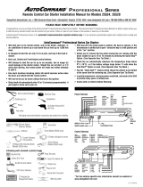
PL70IM
© 2000 Copyright Magnadyne Corp. 3-10-00 Rev. B
2P Blue
3P White
2P Green
2P Orange
3P Black
+ Parking Lights
[-] Parking Lights
Red Wire 12V+ Input
Red Wire 12V+ Input
Black Wire Ground Input
Yellow Wire 1 Ignition Output
Yellow/White Wire 2 Ignition Output
Vacant 12V+For Relay Coil (ALA-RPT)
Gray Wire Horn Output (-)
Black Wire
Unlock (-),(+) Lock Output
Orange Wire 2nd Unlock(-) Output
Red Wire
Lock(-),Unlock(+) Output
Parking Lights +/-
Program Jumper
Blue/White Wire Tach Signal Input
Not Used
Blue Wire Hood Switch
Green Wire (-) Door Trigger
(See Auto Door Locking)
Violet Wire (+) Door Trigger
(See Auto Door Locking)
Vacant Trunk-Pop Output (-) (ALA-RPT)
Red/White Wire Parking Lights
(+) or (-) Output
Pink Wire Brake Switch Turn Off
White/Black Wire
(-) Instant Start & Turn Off Input
Antenna Receiver
Mount on Windshield
Green Wire
(-) Factory Disarm Output Upon RS & RKE
Orange Wire Starter Output
Brown Wire Heater/AC Output
20 A
20 A
Programming Switch
Gray Wire (-) Ground
Upon Remote Start Signal
Yellow Wire
(+) with Ignition Activated
Wiring Diagram
/