Page is loading ...

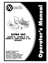
ULTRAV AC®QDS
LAZERZ®,LAZERZ®AS
SERIESX,ANDLAZERZ®AS
MODELS
ForUltraVacSerialNos.
850,000&Higher
(TotLazerZ(LZZ)and
LazerZASSeriesX(LZAS)Units
SerialNos.790,000&Higher)
(TotLazerZAS(LZA)Units
SerialNos.850,000&Higher)
PartNo.4500-605Rev.A

Exmarkreservestherighttomakechangesor
addimprovementstoitsproductsatanytime
withoutincurringanyobligationtomakesuch
changestoproductsmanufacturedpreviously.
Exmark,oritsdistributorsanddealers,accept
noresponsibilityforvariationswhichmaybe
evidentintheactualspecicationsofitsproducts
andthestatementsanddescriptionscontained
inthispublication.
©2009—ExmarkMfg.Co.,Inc.
IndustrialParkBox808
Beatrice,NE68310
2
Contactusatwww.Exmark.com.
PrintedintheUSA
AllRightsReserved

Introduction
CONGRATULATIONSonthepurchaseofyour
ExmarkUltraVac.Thisproducthasbeencarefully
designedandmanufacturedtogiveyouamaximum
amountofdependabilityandyearsoftrouble-free
operation.
Thismanualcontainsoperating,maintenance,
adjustment,andsafetyinstructionsforyourExmark
UltraVac.
BEFOREOPERATINGYOURMOWER,
CAREFULLYREADTHISMANUALINITS
ENTIRETY.
Byfollowingtheoperating,maintenance,andsafety
instructions,youwillprolongthelifeofyourUltra
Vac,maintainitsmaximumefciency,andpromote
safeoperation.
Ifadditionalinformationisneeded,orshouldyou
requiretrainedmechanicservice,contactyour
authorizedExmarkequipmentdealerordistributor.
Exmarkpartsmanualsareavailableonlineat
http://www.exmark.com/manuals.htm.
AllExmarkequipmentdealersanddistributorsare
keptinformedofthelatestmethodsofservicing
andareequippedtoprovidepromptandefcient
serviceintheeldorattheirservicestations.They
carryamplestockofservicepartsorcansecurethem
promptlyforyoufromthefactory.
AllExmarkpartsarethoroughlytestedandinspected
beforeleavingthefactory,however,attentionis
requiredonyourpartifyouaretoobtainthefullest
measureofsatisfactionandperformance.
Wheneveryouneedservice,genuineExmarkparts,
oradditionalinformation,contactanAuthorized
ServiceDealerorExmarkCustomerServiceandhave
themodelandserialnumbersofyourproductready.
Figure1identiesthelocationofthemodelandserial
numbersontheproduct.Writethenumbersinthe
spaceprovided.
Figure1
LZUVQD11Units
1.Modelandserialnumberlocation
Figure2
LZUVQD7Units
1.Modelandserialnumberlocation
ModelNo.
SerialNo.
3

Contents
Introduction...........................................................3
Safety.....................................................................5
SafetyAlertSymbol.........................................5
SafeOperatingPractices..................................5
SafetyandInstructionalDecals.......................8
Specications.......................................................10
ModelNumbers............................................10
Systems.........................................................10
Dimensions...................................................10
TorqueRequirements....................................10
ProductOverview................................................11
Operation.............................................................11
Pre-Start........................................................11
OperatingInstructions..................................11
Transporting.................................................18
Maintenance.........................................................20
RecommendedMaintenanceSchedule(s)...........20
PeriodicMaintenance.......................................20
CheckBlowerHousing/Impeller...................20
CheckDoorClothMesh................................20
CheckExhaustDiverter.................................21
LubricateGreaseFittings...............................21
CheckConditionofBelt................................21
Adjustments.....................................................22
AdjustingtheBlowerDriveBelt
Position.....................................................22
AdjustingtheDoorLinkage...........................22
Cleaning...........................................................24
CleanMuferandRearFrameArea................24
CleanRearScreenInHopper.........................24
CleanBlower.................................................24
Storage.................................................................25
HandleStorage..............................................25
Troubleshooting...................................................26
4

Safety
Safety
SafetyAlertSymbol
ThisSafetyAlertSymbol(Figure3)isusedbothin
thismanualandonthemachinetoidentifyimportant
safetymessageswhichmustbefollowedtoavoid
accidents
Thissymbolmeans:ATTENTION!BECOME
ALERT!YOURSAFETYISINVOLVED!
Figure3
1.Safetyalertsymbol
Thesafetyalertsymbolappearsaboveinformation
whichalertsyoutounsafeactionsorsituations
andwillbefollowedbythewordDANGER,
WARNING,orCAUTION.
DANGER:Whitelettering/Redbackground.
Indicatesanimminentlyhazardoussituationwhich,if
notavoided,Willresultindeathorseriousinjury.
WARNING:Blacklettering/Orangebackground.
Indicatesapotentiallyhazardoussituationwhich,if
notavoided,Couldresultindeathorseriousinjury.
CAUTION:Blacklettering/Yellowbackground.
Indicatesapotentiallyhazardoussituationwhich,if
notavoided,Mayresultinminorormoderateinjury.
Thismanualusestwootherwordstohighlight
information.Importantcallsattentiontospecial
mechanicalinformationandNoteemphasizes
generalinformationworthyofspecialattention.
SafeOperatingPractices
Training
•ReadthetractorandUltraVacOperator’sManuals
andothertrainingmaterial.Iftheoperator(s)or
mechanic(s)cannotreadEnglishitistheowner’s
responsibilitytoexplainthismaterialtothem.
•Becomefamiliarwiththesafeoperationofthe
equipment,operatorcontrols,andsafetysigns.
•Alloperatorsandmechanicsshouldbetrained.
Theownerisresponsiblefortrainingtheusers.
•Neverletchildrenoruntrainedpeopleoperate
orservicetheequipment.Localregulationsmay
restricttheageoftheoperator.
•Onlyadultsandmatureteenagersshouldoperate
amower,andevenmatureteenagersshouldhave
adultsupervision.Besureateenager:
1.hasreadandunderstandstheOperator’s
Manualandrecognizestherisksinvolved;
2.issufcientlymaturetousecaution;and
3.isofsufcientsizeandweighttooperate
thecontrolscomfortablyandtomanagethe
mowerwithouttakingrisks.
•Theowner/usercanpreventandisresponsible
foraccidentsorinjuriesoccurringtohimselfor
herself,otherpeopleorproperty.
Preparation
•Evaluatetheterraintodeterminewhataccessories
andattachmentsareneededtoproperlyandsafely
performthejob.Onlyuseonmachinesapproved
byExmark.
•Wearappropriateclothingincludingsafetyglasses,
substantialfootwear,longtrousers,andhearing
protection.DoNotoperatewhenbarefootor
whenwearingopensandals.
CAUTION
Thismachineproducessoundlevelsin
excessof85dBAattheoperator’searand
cancausehearinglossthroughextended
periodsofexposure.
Wearhearingprotectionwhenoperatingthis
machine.
•Inspecttheareawheretheequipmentistobe
usedandremoveallrocks,toys,sticks,wires,
bones,andotherforeignobjectswhichcanbe
thrownbythemachineandmaycausepersonal
injurytotheoperatororbystanders.
Operation
•Operateonlyindaylightorgoodarticiallight,
keepingawayfromholesandhiddenhazards.
•Nevermowwiththedischargedeectorraised,
removedoralteredunlessthereisagrass
5

Safety
collectionsystemormulchkitinplaceand
workingproperly.
DANGER
Therearerotatingbladesintheblowerand
underthemowerdeck.Bladecontactcan
causeseriousoperatororbystanderinjury
orevendeath.
•DoNotreachintoblowerunlessrotation
indicatorhasstopped.DisengagePTO,
stopengine,removekey,waitforall
movingpartstostop.Engageparking
brake.
•Neveroperatemowerunlessdischarge
deector,entiregrasscollectionsystem,
ormulchkitisinstalled.
•Stopengine,waitforallmovingpartstostop,
removekeyandengageparkingbrake:
–Beforechecking,cleaningorworkingonthe
mower.
–Afterstrikingaforeignobjectorabnormal
vibrationoccurs(inspectthemowerfor
damageandmakerepairsbeforerestarting
andoperatingthemower).
–Beforeclearingblockages.
–Wheneveryouleavethemower.
WARNING
Hands,feet,hair,clothing,oraccessoriescan
becomeentangledinrotatingparts.Contact
withtherotatingpartscancausetraumatic
amputationorseverelacerations.
•DoNotoperatethemachinewithout
guards,shields,andsafetydevicesin
placeandworkingproperly.
•Keephands,feet,hair,jewelry,orclothing
awayfromrotatingparts.
•Stoptheblades,slowdown,andusecautionwhen
crossingsurfacesotherthangrassandwhen
transportingthemowertoandfromtheareato
bemowed.
•Beawareofthemowerdischargepathanddirect
dischargeawayfromothers.
SlopeOperation
UseExtremecautionwhenmowingand/orturning
onslopesaslossoftractionand/ortip-overcould
occur.Theoperatorisresponsibleforsafeoperation
onslopes.
DANGER
Operatingonwetgrassorsteepslopescan
causeslidingandlossofcontrol.Wheels
droppingoveredges,ditches,steepbanks,or
watercancauserollovers,whichmayresult
inseriousinjury,deathordrowning.
•DoNotmowslopeswhengrassiswet.
•DoNotmowneardrop-offsornearwater.
•DoNotmowslopesgreaterthan15
degrees.
•Reducespeedanduseextremecaution
onslopes.
•Avoidsuddenturnsorrapidspeed
changes.
•Keeptherollbarintheraisedandlocked
positionanduseseatbelt.
•Seeinsidethebackcovertodeterminethe
approximateslopeangleoftheareatobemowed.
•Useawalkbehindmowerand/orahandtrimmer
neardrop-offs,ditches,steepbanksorwater.
(Figure4).
6

Safety
Figure4
1.SafeZone-Usethemowerhereonslopeslessthan15
degrees
2.DangerZone-Useawalkbehindmowerand/orhand
trimmeronslopesgreaterthan15degrees,near
drop-offsandwater.
3.Water
•Removeormarkobstaclessuchasrocks,tree
limbs,etc.fromthemowingarea.Tallgrasscan
hideobstacles.
•Watchforditches,holes,rocks,dipsandrisesthat
changetheoperatingangle,asroughterraincould
overturnthemachine.
•Avoidsuddenstartswhenmowinguphillbecause
themowermaytipbackwards.
•Beawarethatoperatingonwetgrass,acrosssteep
slopesordownhillmaycausethemowertolose
traction.Lossoftractiontothedrivewheelsmay
resultinslidingandalossofbrakingandsteering.
•Alwaysavoidsuddenstartingorstoppingona
slope.Iftireslosetraction,disengagetheblades
andproceedslowlyofftheslope.
•Followthemanufacturer’srecommendationsfor
wheelweightsorcounterweightstoimprove
stability.AlwaysinstallandremovetheUltraVac,
includingcounterweights,asinstructed.Failure
todosowillcauseareductioninstabilityor
traction.DoNotoperatethemowerwithonlya
portionoftheUltraVacinstalled.
•Useextremecarewithgrasscatchersor
attachments.Thesecanchangethestabilityofthe
machineandcauselossofcontrol.Thestability
andtractionofthemachinewillchangeasthe
UltraVachopperllswithgrassclippings.Use
progressivelygreatercareonslopesasthehopper
lls.
MaintenanceandStorage
•DisengagePTO,setparkingbrake,stopengine
andremovekeyordisconnectsparkplugwire.
Waitforallmovementtostopbeforeadjusting,
cleaningorrepairing.
•Usecarewhencheckingblades.Wraptheblade(s)
orweargloves,andusecautionwhenservicing
them.Onlyreplacedamagedblades.Never
straightenorweldthem.
•Keepallguards,shieldsandallsafetydevicesin
placeandinsafeworkingcondition.
•Checkallboltsfrequentlytomaintainproper
tightness.
•Frequentlycheckforwornordeteriorating
componentsthatcouldcreateahazard.
•Allreplacementpartsmustbethesameas
orequivalenttothepartssuppliedasoriginal
equipment.
7

Safety
SafetyandInstructionalDecals
•Keepallsafetysignslegible.Removeallgrease,
dirtanddebrisfromsafetysignsandinstructional
labels.
•Replaceallworn,damaged,ormissingsafety
signs.
•Whenreplacementcomponentsareinstalled,be
surethatcurrentsafetysignsareafxedtothe
replacedcomponents.
•Ifanattachmentoraccessoryhasbeeninstalled,
makesurecurrentsafetysignsarevisible.
•Newsafetysignsmaybeobtainedfrom
yourauthorizedExmarkequipmentdealeror
distributororfromExmarkMfg.Co.Inc.
•Safetysignsmaybeafxedbypeelingoffthe
backingtoexposetheadhesivesurface.Apply
onlytoaclean,drysurface.Smoothtoremove
anyairbubbles.
•Familiarizeyourselfwiththefollowingsafetysigns
andinstructionlabels.Theyarecriticaltothesafe
operationofyourExmarkcommercialmower.
1-653558
98-5954
103-6604
LZUVQD7UnitsOnly
103-6605
103-6607
LZUVQD11UnitsOnly
8

Safety
103-3508
LZUVQD7UnitsOnly
109-5890
LZUVQD11UnitsOnly
9

Specications
Specications
ModelNumbers
SerialNos:850,000andHigher
LZUVQD7–FitsLazerZ(LZZ),LazerZASSeriesX(LZAS),andLazerZAS(LZA)with48or52inchdeck.
LZUVQD11–FitsLazerZ(LZZ)andLazerZASSeriesX(LZAS)with60or72inchdeck.FitsLazerZAS(LZA)
with60inchdeck.
Systems
BaggingSystem
•CollectionHopper:
–SteelandPolyethylenehopper.Commercial
grade,clothmeshdoorwithreinforced
bottom.
–LZUVQD7Capacity:7.0bushels
–LZUVQD11Capacity:11.0bushels
•DumpMechanism:Manualdumpfromseat
•BlowerTube:Fixed,abrasionresistantmolded
polyethylene.
•Impeller:5–bladed,1/4inch(6.4mm)thick
abrasionresistantsteel,withverticalaxis.
•Impellerbearings:1inch(2.5cm)sealed
non-greaseablebearings.
Dimensions
OverallWidth:
LZUVQD7
w/UltraVacQDS
LazerZw/48inchDeck
62.50inches(158.8cm)
LazerZw/52inchDeck
67.75inches(172.1cm)
LZUVQD11
w/UltraVac
LazerZw/60inchDeck
75.00inches(190.5cm)
LazerZw/72inchDeck
87.25inches(221.6cm)
OverallLength:
LZUVQD7
w/UltraVac
LazerZw/48inchDeck
102.00inches(259.1cm)
LazerZw/52inchDeck
102.00inches(259.1cm)
LZUVQD11
w/UltraVac
LazerZw/60inchDeck
106.50inches(270.5cm)
LazerZw/72inchDeck
109.50inches(278.1cm)
CurbWeight:
LZUVQD7
UltraVacWeight
Forunitsw/48inchDeck
(3toeboardweights)
331lb(150kg)
Forunitsw/52inchDeck
(2toeboardweights)
288lb(130kg)
LZUVQD11
UltraVacWeight
Forunitsw/60inchDeck
(2toeboardweights)
477lb(216kg)
Forunitsw/72inchDeck
(1toeboardweights)
434lb(197kg)
TorqueRequirements
BoltLocation
Torque
ImpellerSpindleBottom
Nut
55-60ft-lb(75-81N-m)
ImpellerSpindleTopNut75-80ft-lb(102-108N-m)
10

Operation
ProductOverview
Figure5
1.Hopper4.Blower
2.Casterweight
(LZUVQD11UnitsOnly)
5.Tube
3.Toeboardweight6.Door
Operation
Note:Determinetheleftandrightsidesofthe
machinefromthenormaloperatingposition.
Important:ForSerialNumbers790,000and
higher,multipleaccessoriesaddedtoabase
unitcanchangethestabilityofthemachine.
Readtheunitoperator’smanualtodetermine
ifcounterbalanceweightsarenecessaryforthe
accessoriesinstalledontheunit.
Important:Duetotheaddedweightofthe
UltraVac,itisimportanttoensuretheparking
brakeonyourmowerisadjustedproperly.Before
installingtheUltraVac,makesuretore-adjust
theparkingbrakeonyourmowerasoutlinedin
the“AdjustingtheParkingBrake”procedurein
theMaintenancesectionofthetractorOperator’s
manual.
Pre-Start
Makesureyouunderstandthecontrols,their
locations,theirfunctions,andtheirsafety
requirements.
Ensuretheblower,doormesh,tubesandhopperare
ingoodcondition,properlyattached,andlatched.
Important:Verifythatthereinforcedbumpers
areinstalledonyourunitpriortooperation.
RefertotheMaintenancesectionandperformallthe
necessaryinspectionandmaintenancesteps.
OperatingInstructions
Mowing
1.TheUltraVacbloweroperateswhenPTOis
engaged.Besurethatallpersonsareclearof
themowerdeckbeforeengagingthecutting
blades.Setthethrottleto“midway”position.Pull
outwardonthePTOswitchtothe“ROTATE”
position.Acceleratetofullthrottletobegin
mowing.
2.TodisengagethePTOandblower,setthe
throttleto“midway”position.Pushinonthe
PTOswitchtothe“STOP”positiontostopthe
cuttingbladesandblower.Thecuttingbladeswill
requireaslightlylongeramountoftimetocome
toacompletestopwhentheblowerisinstalled
onthedeck.Verifythatallrotationindicators
11

Operation
havestoppedbeforeclearingblowerassemblyor
mowerdeck
3.Toemptythehopper,rstdisengagethePTO.
Liftuponthehandletoopenthedoorandempty
thehopper.Iftheunitistobedrivenontoatruck
ortrailerwiththehopperfull,alwaysbackthe
unituptheramp.Thiswillreducethechanceof
rearwardtipup.SeetheTransportingsection
foradditionalinformationregardingloadinga
unitonatruckortrailer.
4.Closeandlatchthedoorbeforecontinuing
mowing.DoNotengagethecuttingbladeswhile
thedoorisintheopenposition.
Tipsformowingconditions:
•Whenmowinginareaswithsandysoil,use
lowliftbladesonthecuttingdeckandhigher
cuttingheightstominimizewearontheblower
components.
•Whenmowinginwetconditions,suchasjustafter
arainorinheavydew,uselowliftbladesonthe
cuttingdecktominimizepluggingoftheblower.
•Maintainingagroundspeedthatdoesnotpull
downtheengineRPMwillallowforthehighest
productivityandbestqualityofcut.Boggingthe
engineRPMdownbygoingtoofastwillcause
pluggingandqualityofcutissues.
•WhentheUltraVacgetsfull,thesoundof
theblowerwillchangeandtherewillbeslight
blowoutfromthefrontrightcornerofthedeck.
EmptyingtheUltraVacatthispointwillminimize
thepotentialforthetubetoplug.
CollectionSystemRemovalforSide
Discharge
1.Emptythehopper.
CAUTION
Thehopperassemblyisheavywhenitisfull,
whichmaymakeitdifculttoremovethe
hopperassemblyfromtheunit.Theentire
hopperassemblymayfall,whichmaycause
injury.
Priortoremovingthehopperassemblyfrom
theunit,rstemptythecontents.
2.DisengagethePTO,stopengine,waitforall
movingpartstostop,andremovekey.Engage
parkingbrake.
3.Removethedischargetubebyreleasingthelatches
attheblower.Slidethetubeoffthebloweroutlet
andremovetheupperendfromthehopper.
Figure6
1.Hopper7.Toeboardweight
2.Reinforcedbumpers
8.Beltcover
3.Clevispin
9.Blower
4.Casterarmweight
10.Tubes
5.Hairpin11.Door
6.ForLZUVQD11Units
Only
4.Removetheknobfromthebeltcoverbracketand
takeoffthebeltcover.
Figure7
1.Beltcoverbracket4.Belt
2.Beltcover5.Decksheave
3.Knob
12

Operation
CAUTION
Thedecksheavewillbecomeveryhot.
Touchingahotdecksheavecancausesevere
burns.
Allowthedecksheavetocoolcompletely
beforeremovingthebelt.
5.Pulltheidlerreleasehandleandremovethebelt
fromtheuppergrooveofthedecksheave.
6.Unlatchthefrontendoftheblower.Pivotthe
blowerbackandliftitoffthedeck.
Figure8
1.Blowerlatch2.Pivotthebloweraway
fromthedeck
7.Installthedischargedeectorusingthechute
pivotpinandhairpin(seeFigure9).
Figure9
Viewedfromtherightside
1.Hairpin
3.Dischargedeector
2.Chutepivotpin
WARNING
Anuncovereddischargeopeningwill
allowobjectstobethrowninoperator’sor
bystander’sdirection.Also,contactwith
bladecouldoccur.Thrownobjectsorblade
contactcancauseseriousinjuryorkillyou
orbystanders.
Neveroperatemowerunlessdischarge
deector,orentiregrasscollectionsystem,or
mulchkitisinstalled.
8.Re-installthebeltcoverandtightentheknob.
9.LZUVQD11UnitsOnly:
Removethehandlefromthehopperbyrst
rotatingthespringclevispinupwardtounlatch
itfromthehandlelink.Removethespringclevis
pinfromtheactuationarmandrotatedownward.
Attachthelinktothehandlemounttaband
re-installthespringclevispinontothehandlelink.
Figure10
1.Handleassembly5.Actuationarmbracket
2.Handlelink6.Handlemounttab
3.Rotateupward7.Retainingboltandnut
4.Springclevispin
Note:Theentirehandleassemblycanbetaken
offtheunitbyremovingtheretainingboltand
nut(seeFigure10).
10.Removethehopperassembly.DoNotusethe
exhaustdiverterasahandlewhenremovingthe
hopper.
13

Operation
CAUTION
Theexhaustdiverterishot.Touchingahot
exhaustdivertercancausesevereburns.
Allowtheexhaustdivertertocoolcompletely
beforeremovingthehopperassembly.
A.Pushandholdthehopperassemblytowards
theunitandpullthehairpinsandmountpins
fromframemountbarrellocatedoneachside
oftheframelegs.
WARNING
Whenthemountpinshavebeenremoved,
thehopperassemblymayfall.Afalling
hopperassemblymaycauseinjury.
Usecarewhenthemountpinsareremoved
andifnecessary,useassistancewhen
loweringthehopperassemblytotheground.
B.Ifnecessary,useassistanceandcarefullylower
thehopperassemblytotheground.
C.Re-insertthemountpinsintotheframe
mountbarrelandsecurewiththehairpin.
11.Theremovableweightsmustberemovedfrom
theunit.Toremovetheweightonthefrontof
thetoeboard,removethetwohairpinsthatretain
itandthenliftitfromthemountbracket.The
bracketboltedtothetoeboardremainsonthe
unit.
FortheLZUVQD11Units:Removethecaster
weightsbylooseningtheclampingknobsuntilthe
weightcanbemovedrelativetothecasterarm.
Removethehairpinsandclevispinsthathold
theweightstothecasterarms.Carefullyliftthe
weightsoffofthecasterarms.
Note:Theremovableweightsareheavy.Use
carewhenliftingthem.Makesurethatyoucan
holdthemsecurelybeforeliftingthem.Use
cautionwhenpositioningyourhandssothatyou
DoNotsetthemdownonyourhandsorngers.
Note:TheportionsoftheUltraVaccollection
systemthatarenotboltedtothemowerare
designedtobeinstalledorremovedintheir
entirety.DoNotoperatethemowerwithonlya
portionoftheUltraVacinstalled.
WARNING
Casterortoeboardweightsinstalledwithout
thecollectionsystemmaycauselossof
tractionandsteeringcontrol.Lossofcontrol
canresultinanaccidentwhichmaycause
death,injury,orpropertydamage.
InstallcasterortoeboardweightsONLY
whenthecollectionsystemisinstalled.
12.Themachinecannowbeusedforsidedischarge
mowing.
CollectionSystemInstallation
Important:Verifythatthereinforcedbumpers
areinstalledonyourunitpriortooperation.
Important:Duetotheaddedweightofthe
UltraVac,itisimportanttoensuretheparking
brakeonyourmowerisadjustedproperly.Before
installingtheUltraVac,makesuretore-adjust
theparkingbrakeonyourmowerasoutlinedin
the“AdjustingtheParkingBrake”procedurein
theMaintenancesectionofthetractorOperator’s
manual.
1.Stopengine,removekey,andwaitforallmoving
partstostop.Engageparkingbrake.
2.Removehairpinandchutepivotpin.Remove
dischargedeector.Pivotpinandhairpinmaybe
storedinthepivotholesofthedischargedeector
duringbaggingoperation.
3.Laythehopperassemblydownasshownin
Figure11.
Figure11
1.Lowermountbar2.Framenotch
Note:ForLZUVQD7Units:Makesurethe
handleisunfoldedbeforeinstallingthehopper
assembly.
14

Operation
4.Removethehairpinfromthemountpinandpull
themountpinoutoftheframemountbarrel.
5.Pickuptheframelegsandhookthenotchonto
thelowermountbar(seeFigure11).
6.Liftthehopperassemblyandpivotitupward
towardthebackoftheunit(seeFigure12).
Figure12
1.Rotatehopperassembly5.Framemountbarrel
2.Rearbumper6.Hairpin
3.Mountbracket7.Mountpin
4.Opening
7.Continuetopushthehopperassemblyforward
untilitcontactsthemountbracket.
8.Adjusttheexhaustdiverterupordowninthe
slotssoittsoverthemufer.
9.Ifneeded,installwashersbetweentheexhaust
diverterandtheframetospacetheguardoutward.
10.Installthemountpinintotheframemount
barrel.Makesurethatitextendsintotheopening
betweentherearbumperandthemountbracket
(seeFigure12).
11.Aligntheholesinthemountpinandframe
mountbarrelandinsertthehairpintolockthe
hopperassemblyintoplace.
12.Tightenthehardwareontheexhaustdiverter.
13.IfthehandlewasremovedontheLZUVQD11,
installthehandleassemblytotheunitbyfastening
theboltandnutasshowninFigure13.Unlatch
thespringclevispinfromthehandlelink.Rotate
thehandlelinktowardstheactuationarmbracket
andaligntheholes.Insertthespringclevispin
androtateitdownwardtolatchitontothehandle
link.
Figure13
1.Handlelink4.Handleassembly
2.Actuationarmbracket5.Nut
3.Springclevispin
6.Bolt
14.Removethebeltcoverontherightsideofthe
deck.
15.Mountthebloweronthedeckbyinsertingthe
mountingpinintothetubeweldedtotherear
cornerofthedeck(seeFigure14).Pivotthe
bloweruntilthefrontpinengagestheslotin
thedeck.Adjustthepositionofthefrontpinif
necessarytoengagetheslot.Usethelatchtolock
theblowerinthisposition.Adjustthetensionon
thelatchtoholdthebloweruptothedeck,yet
allowforreleasebyhand.
Figure14
1.Slot
4.Mountingpin
2.Frontpin5.Decktube
3.Blowerlatch
15

Operation
16.BeltInstallation:
ForSmallDecks:
A.Slipthebeltovertheimpellersheaveonthe
blower.
Note:Itmaybeeasiertoinstallthebeltif
thebeltguideistemporarilyshiftedtoone
sideortemporarilyremoved.Eitherloosen
orremovebothnutsonthetopandbottom
ofthebeltguide.Oncethebeltisinstalled
ontheimpellersheave,reinstallthebeltguide
andtightenallhardware.
Figure15
1.Nut2.Beltguide
B.Pullthespringloadedidlerreleasehandle
backandinstallthebeltintheuppergroove
ofthetopspindlesheave.Thebeltshouldbe
routedasshowninFigure16.
Figure16
SmallDecks—ViewfromT opofBlower
1.Springloadedidler
4.Beltguide
2.Impellersheave5.Decksheave
3.Fixedidler
ForLargeDecks:
Pullthespringloadedidlerbackandslipthebelt
overthetopdecksheave.
Figure17
LargeDecks—ViewfromT opofBlower
1.Impellersheave
3.Springloadedidler
2.Decksheave
17.Positionthebeltcoveratanangleandslideit
underthemowerframe(seeFigure18).
Figure18
1.Blower
3.Mowerframe
2.Beltcover
18.Pushdownonthebackofthecoverandslideit
backwardsundertheblower.
19.Slidethebeltcoverforwarduntilitisseatedunder
bothlipsonthedeck.
16

Operation
Figure19
1.Blower3.Decklip
2.Beltcover
20.Installtheknobanditshardware.
21.Sliptheupperandthelowertubestogether.
22.Inserttheuppertubeintothehopperseal–
pushinthenpulloutsothatthesealisextended
outward.
23.Alignthedimpleontheuppertubewiththeend
ofhoppersealandcenterbetweenthetwoscrews
asshowninFigure20.
Figure20
1.Dimple
24.Setthedeckinlowestcuttingposition.
25.Slidethelowertubeontotheblowerandattach
thelatches.(Makesurethattheuppertubedoes
notmoveoutofalignment).
26.Ifthelowertubeisreplaced,drillthree7/32inch
holesinthelowertubeusingtheuppertubeholes
asreference.SeeFigure21.
27.Removethetubesfromunitandassemblethe
upperandthelowertubesusingthree#10-24
x3/4inchhexwasherheadscrews,three#10
washers,andthree#10-24nylocnuts.Thescrew
headshouldbeinstalledtotheinsideofthe
tubetoprovideminimumobstructiontoow .
Makesurethattheupperandthelowerendsare
orientedproperlyasthetubesareassembled.
(Partinglinesshouldroughlybelinedup.)
Figure21
1.Drilltheholeshere
28.Slidethelowerendofthetubeassemblyoverthe
bloweroutletandalignthenotchwiththetube
latch.Latchthetubetotheblower.
29.Installtheremovableweights.Hookthefronttoe
boardweightsassemblyoverthetopoftheweight
mountingplateandsecurewithtwohairpins(see
Figure22).
WeightQuantities
Deck
Size
48inch52inch60inch72inch
Toe
Board
Weight
3
221
Caster
Weight
——
22
Note:Theremovableweightsareheavy.Use
carewhenliftingthem.Makesurethatyoucan
holdthemsecurelybeforeliftingthem.Use
cautionwhenpositioningyourhandssothatyou
DoNotsetthemdownonyourhandsorngers.
17

Operation
Figure22
1.Toeboardweight2.Hairpin
30.ForLZUVQD11UnitsOnly:
A.Installtheremovablecasterweightsoverthe
casterarms(seeFigure23).
B.Installaclevispinandhairpinoneachcaster
weighttoretainthem.
C.Tightenknobonweightassemblyuntilthe
weightisclampedsecurelytothecasterarm.
Figure23
1.Clevispin
3.Hairpin
2.Knob
4.Casterweight
Transporting
TransportingaUnit
Useaheavy-dutytrailerortrucktotransportthe
machine.Lockbrakeandblockwheels.Securely
fastenthemachinetothetrailerortruckwithstraps,
chains,cable,orropes.Besurethatthetrailerortruck
hasallnecessarylightingandmarkingasrequiredby
law .Secureatrailerwithasafetychain.
CAUTION
Thisunitdoesnothaveproperturn
signals,lights,reectivemarkings,ora
slowmovingvehicleemblem.Drivingona
streetorroadwaywithoutsuchequipment
isdangerousandcanleadtoaccidents
causingpersonalinjury.Drivingonastreet
orroadwaywithoutsuchequipmentmayalso
beaviolationofStatelawsandtheoperator
maybesubjecttotrafcticketsand/ornes.
DoNotdriveaunitonapublicstreetor
roadway.
WARNING
Loadingaunitonatrailerortruckincreases
thepossibilityofbackwardtip-over.
Backwardtip-overcouldcauseseriousinjury
ordeath.
•Useextremecautionwhenoperatinga
unitonaramp.
•Useonlyasingle,fullwidthramp;Do
Notuseindividualrampsforeachside
oftheunit.
•Ifindividualrampsmustbeused,use
enoughrampstocreateanunbroken
rampsurfacewiderthantheunit.
•DoNotexceeda15°anglebetweenramp
andgroundorbetweenrampandtrailer
ortruck.
•Avoidsuddenaccelerationwhiledriving
unituparamptoavoidtippingbackward.
•Avoidsuddendecelerationwhilebacking
unitdownaramptoavoidtipping
backward.
LoadingaUnit
DoNottransporttheunitwiththehopperfull.
Emptythehopperbeforeattemptingtoloadunit
ontrailerortruck.Thiswillreducethechance
ofrearwardtipup.Useextremecautionwhen
loadingunitsontrailersortrucks.Onefullwidth
rampthatiswideenoughtoextendbeyondtherear
tiresisrecommendedinsteadofindividualrampsfor
18

Operation
eachsideoftheunit.Thelowerrearsectionofthe
tractorframeextendsbackbetweentherearwheels
andservesasastopfortippingbackward.Having
afullwidthrampprovidesasurfacefortheframe
memberstocontactiftheunitstartstotipbackward.
Ifitisnotpossibletouseonefullwidthramp,use
enoughindividualrampstosimulateafullwidth
continuousramp.
Rampshouldbelongenoughsothattheangles
betweentherampandthegroundandtherampand
thetrailerortruckDoNotexceed15°.Asteeper
anglemaycausemowerdeckcomponentstoget
caughtastheunitmovesfromramptotraileror
truck.Steeperanglesmayalsocausetheunittotip
backward.Ifloadingonornearaslope,position
thetrailerortrucksoitisonthedownsideofthe
slopeandtherampextendsuptheslope.Thiswill
minimizetherampangle.Thetrailerortruckshould
beaslevelaspossible.
Important:DoNotattempttoturntheunit
whileontheramp,youmaylosecontroland
driveofftheside.
Avoidsuddenaccelerationwhendrivinguparamp
andsuddendecelerationwhenbackingdownaramp.
Bothmaneuverscancausetheunittotipbackward.
RolloverProtectionSystem(ROPS)
Therollbarhasanintermediatepositionthatallows
thebartobeloweredtoprovideoverheadclearance,
butnotrestdirectlyontheUltraVacassembly.Insert
a1/2x3inchboltand1/2inchnut(orExmark
serviceparts:clevispinP/N283-55andhairpinP/N
1-806005)intothedownstopholeoneachsideand
lowertherollbar.
Figure24
1.Intermediateposition2.Downstophole
Important:Therollbarisanintegraland
effectivesafetydevice.Keeptherollbarinthe
raisedandlockedpositionwhenoperatingthe
mower.Lowertherollbartemporarilyonlywhen
absolutelynecessary.
RefertotheOperator’smanualsuppliedwithyour
tractorforadditionalROPSsafetyandoperating
instructions.
19

Maintenance
Maintenance
Note:Determinetheleftandrightsidesofthemachinefromthenormaloperatingposition.
WARNING
Whilemaintenanceoradjustmentsarebeing
made,someonecouldstarttheengine.
Accidentalstartingoftheenginecould
seriouslyinjureyouorotherbystanders.
Removethekeyfromtheignitionswitch,
engageparkingbrake,andpullthewire(s)
offthesparkplug(s)beforeyoudoany
maintenance.Alsopushthewire(s)aside
soitdoesnotaccidentallycontactthespark
plug(s).
WARNING
Theenginecanbecomeveryhot.Touching
ahotenginecancausesevereburns.
Allowtheenginetocoolcompletelybefore
serviceormakingrepairsaroundtheengine
area.
RecommendedMaintenanceSchedule(s)
MaintenanceService
Interval
MaintenanceProcedure
Beforeeachuseordaily
•Checktheblowerhousing/impeller.
•Checkdoorclothmesh.
•Checkexhaustdiverter.
•Cleanmuferandrearframearea.
•Cleanrearscreeninthehopper.
Every25hours
•Lubricategreasettings.
Every50hours
•Checkconditionofbelt.
Yearlyorbeforestorage
•Cleanblower.
PeriodicMaintenance
CheckBlower
Housing/Impeller
ServiceInterval:Beforeeachuseordaily
1.Stopengine,waitforallmovingpartstostop,and
removekey.Engageparkingbrake.
2.Inspectforwearordamagedaily.Replaceor
repairwornpartsasneeded
Note:Whenmowinginareaswithsandysoil,
uselowliftbladesonthecuttingdeckandhigher
cuttingheightstominimizewearontheblower
components.
CheckDoorClothMesh
ServiceInterval:Beforeeachuseordaily
1.Stopengine,waitforallmovingpartstostop,and
removekey.Engageparkingbrake.
2.Inspectthedoorclothmeshforwear,tears,or
damage.
20
/