Page is loading ...

G032032
ULTRA V AC®
COLLECTION
SYSTEM
LZUVQD7,LZUVQD11
ForUltraVacSerialNos.
406,294,345&Higher
(TofitLazerZUnits
SerialNos790,000&Higher)
7-Bushel–Fitsunitswith
48or52inchdeck
11-Bushel–Fitsunitswith
60or72inchdeck
PartNo.4504-776Rev.A

WARNING
CALIFORNIA
Proposition65Warning
Useofthisproductmaycauseexposure
tochemicalsknowntotheStateof
Californiatocausecancer,birthdefects,
orotherreproductiveharm.
Exmarkreservestherighttomakechangesor
addimprovementstoitsproductsatanytime
withoutincurringanyobligationtomakesuch
changestoproductsmanufacturedpreviously.
Exmark,oritsdistributorsanddealers,accept
noresponsibilityforvariationswhichmaybe
evidentintheactualspecicationsofitsproducts
andthestatementsanddescriptionscontained
inthispublication.
©2019ExmarkMfg.Co.,Inc.
2101AshlandAve
Beatrice,NE68310
2
Contactusatwww.Exmark.com.
PrintedintheUSA
AllRightsReserved

Introduction
CONGRATULATIONSonthepurchaseofyour
ExmarkUltraVac.Thisproducthasbeencarefully
designedandmanufacturedtogiveyouamaximum
amountofdependabilityandyearsoftrouble-free
operation.
Thismanualcontainsoperating,maintenance,
adjustment,andsafetyinstructionsforyourExmark
UltraVac.
BEFOREOPERATINGYOURMOWER,
CAREFULLYREADTHISMANUALINITS
ENTIRETY.
Byfollowingtheoperating,maintenance,and
safetyinstructions,youwillprolongthelifeofyour
UltraVac,maintainitsmaximumefciency,and
promotesafeoperation.
Important:Tomaximizesafety,performance,
andproperoperationofthismachine,itis
essentialthatalloperatorscarefullyreadand
fullyunderstandthecontentsoftheOperator’s
manualprovidedwiththeproduct.Safe
operationofExmarkequipmentisessential.
Failuretocomplywiththeoperatinginstructions
orreceivepropertrainingmayresultininjury.
Gotohttps://www.Exmark.comforadditional
safeoperationinformation,suchassafetytips,
trainingmaterials,andOperator’smanuals.
AllExmarkequipmentdealersanddistributorsare
keptinformedofthelatestmethodsofservicing
andareequippedtoprovidepromptandefcient
serviceintheeldorattheirservicestations.They
carryamplestockofservicepartsorcansecurethem
promptlyforyoufromthefactory.
AllExmarkpartsarethoroughlytestedandinspected
beforeleavingthefactory,however,attentionis
requiredonyourpartifyouaretoobtainthefullest
measureofsatisfactionandperformance.
Wheneveryouneedservice,genuineExmarkparts,
oradditionalinformation,contactanAuthorized
ServiceDealerorExmarkCustomerServiceandhave
themodelandserialnumbersofyourproductready.
Figure1andFigure2identifythelocationofthe
modelandserialnumbersontheproduct.Writethe
numbersinthespaceprovided.
g031991
Figure1
7-BushelUnit
1.Modelandserialnumberlocation
g032034
Figure2
11-BushelUnit
1.Modelandserialnumberlocation
ModelNo.
SerialNo.
Forcompletewarrantydetails,see
https://www.Exmark.com.Youmayalsocall
us402-223-6375torequestawrittencopyofthe
product’swarranty.
3

Contents
Introduction...........................................................3
Safety.....................................................................5
SafetyAlertSymbol.........................................5
GeneralSafetyInformation.............................5
SafetyandInstructionalDecals.......................6
Specications.........................................................8
Systems...........................................................8
Dimensions.....................................................8
TorqueRequirements......................................8
ProductOverview..................................................9
Operation...............................................................9
BeforeOperation............................................9
BeforeOperationSafety..................................9
Pre-Start.........................................................10
OperatingInstructions...................................10
DuringOperationSafety.................................10
AfterOperation..............................................18
Maintenance..........................................................19
MaintenanceSafety.............................................19
RecommendedMaintenanceSchedule(s)............19
PeriodicMaintenance........................................20
CheckBlowerHousing/Impeller....................20
CheckDoorClothMesh.................................20
CheckExhaustDiverter..................................20
LubricateGreaseFittings................................20
CheckConditionofBelt.................................21
Adjustments......................................................22
AdjustingtheBlowerDriveBelt
Position......................................................22
AdjustingtheDoorLinkage............................22
Cleaning............................................................24
CleanMuferandRearFrameArea.................24
CleanRearScreenInHopper..........................24
CleanBlower..................................................24
Storage..................................................................25
HandleStorage...............................................25
Troubleshooting....................................................26
CaliforniaProposition65Warning
Information...............................................27
4

Safety
Safety
SafetyAlertSymbol
ThisSafetyAlertSymbol(Figure3)isusedbothin
thismanualandonthemachinetoidentifyimportant
safetymessageswhichmustbefollowedtoavoid
accidents.
Thissymbolmeans:ATTENTION!BECOME
ALERT!YOURSAFETYISINVOLVED!
g000502
Figure3
SafetyAlertSymbol
Thesafetyalertsymbolappearsaboveinformation
whichalertsyoutounsafeactionsorsituations
andwillbefollowedbythewordDANGER,
WARNING,orCAUTION.
DANGER:Indicatesanimminentlyhazardous
situationwhich,ifnotavoided,Willresultindeathor
seriousinjury.
WARNING:Indicatesapotentiallyhazardous
situationwhich,ifnotavoided,Couldresultindeath
orseriousinjury.
CAUTION:Indicatesapotentiallyhazardous
situationwhich,ifnotavoided,Mayresultinminor
ormoderateinjury.
Thismanualusestwootherwordstohighlight
information.Importantcallsattentiontospecial
mechanicalinformationandNoteemphasizes
generalinformationworthyofspecialattention.
GeneralSafetyInformation
Thismachineiscapableofamputatinghandsand
feetandofthrowingobjects.Exmarkdesignedand
testedthismachinetoofferreasonablysafeservice;
however,failuretocomplywithsafetyinstructions
mayresultininjuryordeath.
•Read,understand,andfollowallinstructions
andwarningsinthemowerandUltraVac
Operator’sManualsandothertrainingmaterial,
onthemachine,engine,andattachments.All
operatorsandmechanicsshouldbetrained.If
theoperator(s)ormechanic(s)cannotreadthis
manual,itistheowner’sresponsibilitytoexplain
thismaterialtothem;otherlanguagesmaybe
availableonourwebsite.
•Onlyallowtrained,responsible,andphysically
capableoperatorsthatarefamiliarwiththesafe
operation,operatorcontrols,andsafetysignsand
instructionstooperatethemachine.Neverlet
childrenoruntrainedpeopleoperateorservice
theequipment.Localregulationsmayrestrictthe
ageoftheoperator.
•DoNotputyourhandsorfeetnearmoving
componentsofthemachine.
•Neveroperatethemachinewithdamagedguards,
shields,orcovers.Alwayshavesafetyshields,
guards,switchesandotherdevicesinplaceandin
properworkingcondition.
•Stopthemachine,shutofftheengine,andremove
thekeybeforeservicing,fueling,orunclogging
themachine.
5

Safety
SafetyandInstructionalDecals
•Keepallsafetysignslegible.Removeallgrease,
dirtanddebrisfromsafetysignsandinstructional
labels.
•Replaceallworn,damaged,ormissingsafety
signs.
•Whenreplacementcomponentsareinstalled,be
surethatcurrentsafetysignsareafxedtothe
replacedcomponents.
•Ifanattachmentoraccessoryhasbeeninstalled,
makesurecurrentsafetysignsarevisible.
•Newsafetysignsmaybeobtainedfrom
yourauthorizedExmarkequipmentdealeror
distributororfromExmarkMfg.Co.Inc.
•Safetysignsmaybeafxedbypeelingoffthe
backingtoexposetheadhesivesurface.Apply
onlytoaclean,drysurface.Smoothtoremove
anyairbubbles.
•Familiarizeyourselfwiththefollowingsafetysigns
andinstructionlabels.Theyarecriticaltothesafe
operationofyourExmarkcommercialmower.
decal106-5517
106-5517
1.Warning—donottouchthehotsurface.
decal112-9028
112-9028
1.Warning—stayawayfrommovingparts;keepallguards
andshieldsinplace.
decal126-4659
126-4659
1.Warning-Hotpulley;allowtocool.
decal126-4661
126-4661
1.Warning-ReadtheOperator’smanualforcorrect
quantityofcounterbalanceweight(s).
2.Lossoftractionandsteeringorreducedstability
hazard-UltraVaccounterbalanceweight(s)installed
withoutUltraVacmaycauselossoftractionand
steeringcontrol.UltraVacinstalledwithoutUltraVac
counterbalanceweight(s)willcausereducedstability.
Installweight(s)onlywhenUltraVacisinstalled.
6

Safety
decal126-4662
126-4662
1.Warning-ReadtheOperator’smanualforcorrect
quantityofcounterbalanceweight(s).
2.Lossoftractionandsteeringorreducedstability
hazard-UltraVaccounterbalanceweight(s)installed
withoutUltraVacmaycauselossoftractionand
steeringcontrol.UltraVacinstalledwithoutUltraVac
counterbalanceweight(s)willcausereducedstability.
Installweight(s)onlywhenUltraVacisinstalled.
decal126-4853
126-4853
1.Impeller/RotatingBladeshazard-Keephandsaway
frommovingparts.Keepallsafetydevicesinplace
andworking.DoNotreachintoblowerunlessrotation
indicatorhasstopped.
decal133-8061
133-8061
decal126-4584
126-4584
1.Impeller/RotatingBladeshazard-Keephandsawayfrommovingparts.Keepallsafetydevicesinplaceandworking.Do
Notreachintoblowerunlessrotationindicatorhasstopped.DisengagePTO,stopengine,removekey,WAITFOR
MOVINGPARTSTOSTOP .
2.Rotationindicator
3.Thrownobjectshazard-Highspeeddischargecancauseinjuryordeath.DoNotrunblowerwithoutentirecollection
systeminstalledandlatched.ReadtheOperator’smanual.
7

Specications
Specications
Systems
BaggingSystem
•CollectionHopper:
–SteelandPolyethylenehopper.Commercial
grade,clothmeshdoorwithreinforced
bottom.
–Capacity:
◊Modelsendingwith“7”:7.0bushels
◊Modelsendingwith“11”:11.0bushels
•DumpMechanism:Manualdumpfromseat
•BlowerTube:Fixed,abrasionresistantmolded
polyethylene.
•Impeller:5–bladed,1/4inch(6.4mm)thick
abrasionresistantsteel,withverticalaxis.
•Impellerbearings:1inch(2.5cm)sealed
non-greaseablebearings.
Dimensions
OverallWidth:
7-Bushel
w/UltraVac
LazerZw/48inchDeck
62.50inches(158.8cm)
LazerZw/52inchDeck
67.75inches(172.1cm)
11-Bushel
w/UltraVac
LazerZw/60inchDeck
75.00inches(190.5cm)
LazerZw/72inchDeck
87.25inches(221.6cm)
OverallLength:
7-Bushel
w/UltraVac
LazerZw/48inchDeck
102.00inches(259.1cm)
LazerZw/52inchDeck
102.00inches(259.1cm)
11-Bushel
w/UltraVac
LazerZw/60inchDeck
106.50inches(270.5cm)
LazerZw/72inchDeck
109.50inches(278.1cm)
CurbWeight:
7-Bushel
UltraVacWeight
Forunitsw/48inchDeck
(3toeboardweights)
331lb(150kg)
Forunitsw/52inchDeck
(2toeboardweights)
288lb(130kg)
11-Bushel
UltraVacWeight
Forunitsw/60inchDeck
(2toeboardweights)
477lb(216kg)
Forunitsw/72inchDeck
(1toeboardweights)
434lb(197kg)
TorqueRequirements
BoltLocation
Torque
ImpellerSpindleBottom
Nut
55-60ft-lb(75-81N-m)
ImpellerSpindleTopNut75-80ft-lb(102-108N-m)
8

Operation
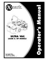
ProductOverview
g032033
Figure4
1.Hopper4.Blower
2.Casterweight(11-Bushel
UnitOnly)
5.Tube
3.Toeboardweight6.Door
Operation
Note:Determinetheleftandrightsidesofthe
machinefromthenormaloperatingposition.
Important:ForSerialNumbers790,000and
higher,multipleaccessoriesaddedtoabase
unitcanchangethestabilityofthemachine.
Readtheunitoperator’smanualtodetermine
ifcounterbalanceweightsarenecessaryforthe
accessoriesinstalledontheunit.
Important:Duetotheaddedweightofthe
UltraVac,itisimportanttoensuretheparking
brakeonyourmowerisadjustedproperly.Before
installingtheUltraVac,makesuretore-adjust
theparkingbrakeonyourmowerasoutlinedin
the“AdjustingtheParkingBrake”procedurein
theMaintenancesectionofthetractorOperator's
manual.
BeforeOperation
BeforeOperationSafety
GeneralSafety
•Evaluatetheterraintodeterminewhataccessories
andattachmentsareneededtoproperlyandsafely
performthejob.Onlyuseonmachinesapproved
byExmark.
•Wearappropriatepersonalprotectiveequipment
suchassafetyglasses,substantialslip-resistant
footwear,andhearingprotection.Tiebacklong
hairandavoidlooseclothingandloosejewelry
whichmaygettangledinmovingparts.
CAUTION
Thismachineproducessoundlevelsinexcess
of85dBAattheoperator’searandcancause
hearinglossthroughextendedperiodsof
exposure.
Wearhearingprotectionwhenoperatingthis
machine.
•Inspecttheareawheretheequipmentistobe
usedandremoveallrocks,toys,sticks,wires,
bones,andotherforeignobjectswhichcanbe
thrownbythemachineandmaycausepersonal
injurytotheoperatororbystanders.
9

Operation
Pre-Start
Makesureyouunderstandthecontrols,their
locations,theirfunctions,andtheirsafety
requirements.
Ensuretheblower,doormesh,tubesandhopperare
ingoodcondition,properlyattached,andlatched.
Important:Verifythatthereinforcedbumpers
areinstalledonthemachinepriortooperation.
RefertotheMaintenancesectionandperformallthe
necessaryinspectionandmaintenancesteps.
OperatingInstructions
DuringOperationSafety
GeneralSafety
Theoperatormustusetheirfullattentionwhen
operatingthemachine.DoNotengageinanyactivity
thatcausesdistractions;otherwise,injuryorproperty
damagemayoccur.
•ThemachinethattheUltraVacattachestowas
designedforoneoperatoronly.Donotcarry
passengersandkeepallothersawayfrommachine
duringoperation.
•Operateonlyindaylightorgoodarticiallight.
•Lightningcancausesevereinjuryordeath.If
lightningisseenorthunderisheardinthearea,
DoNotoperatethemachine;seekshelter.
•Keepawayfromholes,ruts,bumps,rocks,and
otherhiddenhazards.Usecarewhenapproaching
blindcorners,shrubs,trees,tallgrassorother
objectsthatmayhideobstaclesorobscurevision.
Uneventerraincouldoverturnthemachineor
causetheoperatortolosetheirbalanceorfooting.
•Nevermowwiththedischargedeectorraised,
removedoralteredunlessthereisagrass
collectionsystemormulchkitinplaceand
workingproperly.
DANGER
Therearerotatingbladesintheblowerand
underthemowerdeck.Bladecontactcan
causeseriousoperatororbystanderinjuryor
evendeath.
•DoNotreachintoblowerunlessrotation
indicatorhasstopped.DisengagePTO,
stopengine,removekey,waitforall
movingpartstostop.Engageparking
brake.
•Neveroperatemowerunlessdischarge
deector,entiregrasscollectionsystem,
ormulchkitisinstalled.
•Stoptheblades,slowdown,andusecaution
whencrossingsurfacesotherthangrassandwhen
transportingthemowertoandfromtheareato
bemowed.
•Beawareofthemowerdischargepathanddirect
dischargeawayfromothers.Avoiddischarging
materialagainstawallorobstructionasthe
materialmayricochetbacktowardtheoperator.
Stoptheblades,slowdown,andusecaution
whencrossingsurfacesotherthangrassandwhen
transportingthemowertoandfromtheareato
bemowed.
WARNING
Hands,feet,hair,clothing,oraccessoriescan
becomeentangledinrotatingparts.Contact
withtherotatingpartscancausetraumatic
amputationorseverelacerations.
•DoNotoperatethemachinewithout
guards,shields,andsafetydevicesinplace
andworkingproperly.
•Keephands,feet,hair,jewelry,orclothing
awayfromrotatingparts.
•Parkmachineonlevelground.Stopengine,wait
forallmovingpartstostop,removekeyand
engageparkingbrake:
–Beforechecking,cleaningorworkingonthe
mower.
–Afterstrikingaforeignobjectorabnormal
vibrationoccurs(inspectthemowerfor
damageandmakerepairsbeforerestarting
andoperatingthemower).
–Beforeclearingblockages.
10

Operation
–Wheneveryouleavethemower.
•Tragicaccidentscanoccuriftheoperatorisnot
alerttothepresenceofchildren.Childrenare
oftenattractedtothemachineandthemowing
activity.Neverassumethatchildrenwillremain
whereyoulastsawthem.
–Keepchildrenoutofthemowingareaand
underthewatchfulcareofanotherresponsible
adult,nottheoperator.
–Bealertandturnthemachineoffifchildren
enterthearea.
–Beforeandwhilebackingorchanging
direction,lookbehind,down,andside-to-side
forsmallchildren.
–Neverallowchildrentooperatethemachine.
–DoNotcarrychildren,evenwiththeblades
shutoff.Childrencouldfalloffandbe
seriouslyinjuredorinterferewiththesafe
operationofthemachine.Childrenthathave
beengivenridesinthepastcouldsuddenly
appearintheworkingareaforanotherrideand
berunoverorbackedoverbythemachine.
Mowing
1.TheUltraVacbloweroperateswhenPTOis
engaged.Besurethatallpersonsareclearof
themowerdeckbeforeengagingthecutting
blades.Setthethrottleto“midway”position.Pull
outwardonthePTOswitchtothe“ROTATE”
position.Acceleratetofullthrottletobegin
mowing.
2.TodisengagethePTOandblower,setthe
throttleto“midway”position.Pushinonthe
PTOswitchtothe“STOP”positiontostopthe
cuttingbladesandblower.Thecuttingbladeswill
requireaslightlylongeramountoftimetocome
toacompletestopwhentheblowerisinstalled
onthedeck.Verifythatallrotationindicators
havestoppedbeforeclearingblowerassemblyor
mowerdeck.
3.Toemptythehopper,rstdisengagethePTO.
Liftuponthehandletoopenthedoorandempty
thehopper.
Important:DoNottransportthemachine
withthehopperfull.Emptythehopper
beforeattemptingtoloadmachineontrailer
ortruck.Thiswillreducethechanceof
rearwardtipup.
4.Closeandlatchthedoorbeforecontinuing
mowing.DoNotengagethecuttingbladeswhile
thedoorisintheopenposition.
Tipsformowingconditions:
•Whenmowinginareaswithsandysoil,use
lowliftbladesonthecuttingdeckandhigher
cuttingheightstominimizewearontheblower
components.
•Whenmowinginwetconditions,suchasjustafter
arainorinheavydew,uselowliftbladesonthe
cuttingdecktominimizepluggingoftheblower.
•Maintainingagroundspeedthatdoesnotpull
downtheengineRPMwillallowforthehighest
productivityandbestqualityofcut.Boggingthe
engineRPMdownbygoingtoofastwillcause
pluggingandqualityofcutissues.
•WhentheUltraVacgetsfull,thesoundofthe
blowerwillchangeandtherewillbeslightblowout
fromthefrontrightcornerofthedeck.Emptying
theUltraVacatthispointwillminimizethe
potentialforthetubetoplug.
CollectionSystemRemovalforSide
Discharge
1.Emptythehopper.
CAUTION
Thehopperassemblyisheavywhenitisfull,
whichmaymakeitdifculttoremovethe
hopperassemblyfromtheunit.Theentire
hopperassemblymayfall,whichmaycause
injury.
Priortoremovingthehopperassemblyfrom
theunit,rstemptythecontents.
2.DisengagethePTO,stopengine,waitforall
movingpartstostop,andremovekey.Engage
parkingbrake.
3.Removethedischargetubebyreleasingthelatches
attheblower.Slidethetubeoffthebloweroutlet
andremovetheupperendfromthehopper.
11

Operation
g007989
Figure5
1.Hopper7.Toeboardweight
2.Reinforcedbumpers
8.Beltcover
3.Clevispin
9.Blower
4.Casterarmweight
10.Tubes
5.Hairpin11.Door
6.For11-BushelUnitOnly
4.Removetheknobfromthebeltcoverbracketand
takeoffthebeltcover.
g007981
Figure6
1.Beltcoverbracket4.Belt
2.Beltcover5.Decksheave
3.Knob
CAUTION
Thedecksheavewillbecomeveryhot.
Touchingahotdecksheavecancausesevere
burns.
Allowthedecksheavetocoolcompletely
beforeremovingthebelt.
5.Pulltheidlerreleasehandleandremovethebelt
fromtheuppergrooveofthedecksheave.
6.Unlatchthefrontendoftheblower.Pivotthe
blowerbackandliftitoffthedeck.
g032035
Figure7
1.Blowerlatch2.Pivotthebloweraway
fromthedeck
7.Installthedischargedeectorusingthechute
pivotpinandhairpin(seeFigure8).
g009319
Figure8
Viewedfromtherightside
1.Hairpin
3.Dischargedeector
2.Chutepivotpin
12

Operation
WARNING
Anuncovereddischargeopeningwill
allowobjectstobethrowninoperator'sor
bystander'sdirection.Also,contactwith
bladecouldoccur.Thrownobjectsorblade
contactcancauseseriousinjuryorkillyou
orbystanders.
Neveroperatemowerunlessdischarge
deector,orentiregrasscollectionsystem,or
mulchkitisinstalled.
8.Re-installthebeltcoverandtightentheknob.
9.LZUVQD11UnitsOnly:
Removethehandlefromthehopperbyrst
rotatingthespringclevispinupwardtounlatchit
fromthehandlelink.Removethespringclevis
pinfromtheactuationarmandrotatedownward.
Attachthelinktothehandlemounttaband
re-installthespringclevispinontothehandlelink.
g007996
Figure9
1.Handleassembly5.Actuationarmbracket
2.Handlelink6.Handlemounttab
3.Rotateupward7.Retainingboltandnut
4.Springclevispin
Note:Theentirehandleassemblycanbetaken
offtheunitbyremovingtheretainingboltand
nut(seeFigure9).
10.Removethehopperassembly.DoNotusethe
exhaustdiverterasahandlewhenremovingthe
hopper.
CAUTION
Theexhaustdiverterishot.Touchingahot
exhaustdivertercancausesevereburns.
Allowtheexhaustdivertertocoolcompletely
beforeremovingthehopperassembly.
A.Pushandholdthehopperassemblytowards
theunitandpullthehairpinsandmountpins
fromframemountbarrellocatedoneachside
oftheframelegs.
WARNING
Whenthemountpinshavebeenremoved,
thehopperassemblymayfall.Afalling
hopperassemblymaycauseinjury.
Usecarewhenthemountpinsare
removedandifnecessary,useassistance
whenloweringthehopperassemblytothe
ground.
B.Ifnecessary,useassistanceandcarefullylower
thehopperassemblytotheground.
C.Re-insertthemountpinsintotheframe
mountbarrelandsecurewiththehairpin.
11.Theremovableweightsmustberemovedfrom
theunit.Toremovetheweightonthefrontof
thetoeboard,removethetwohairpinsthatretain
itandthenliftitfromthemountbracket.The
bracketboltedtothetoeboardremainsonthe
unit.
Forthe11-BushelUnits:Removethecaster
weightsbylooseningtheclampingknobsuntilthe
weightcanbemovedrelativetothecasterarm.
Removethehairpinsandclevispinsthathold
theweightstothecasterarms.Carefullyliftthe
weightsoffofthecasterarms.
Note:Theremovableweightsareheavy.Use
carewhenliftingthem.Makesurethatyoucan
holdthemsecurelybeforeliftingthem.Use
cautionwhenpositioningyourhandssothatyou
DoNotsetthemdownonyourhandsorngers.
Note:TheportionsoftheUltraVaccollection
systemthatarenotboltedtothemowerare
designedtobeinstalledorremovedintheir
entirety.DoNotoperatethemowerwithonlya
portionoftheUltraVacinstalled.
13

Operation
WARNING
Casterortoeboardweightsinstalledwithout
thecollectionsystemmaycauselossof
tractionandsteeringcontrol.Lossofcontrol
canresultinanaccidentwhichmaycause
death,injury,orpropertydamage.
InstallcasterortoeboardweightsONLY
whenthecollectionsystemisinstalled.
12.Themachinecannowbeusedforsidedischarge
mowing.
CollectionSystemInstallation
Important:Verifythatthereinforcedbumpers
areinstalledonyourunitpriortooperation.
Important:Duetotheaddedweightofthe
UltraVac,itisimportanttoensuretheparking
brakeonyourmowerisadjustedproperly.Before
installingtheUltraVac,makesuretore-adjust
theparkingbrakeonyourmowerasoutlinedin
the“AdjustingtheParkingBrake”procedurein
theMaintenancesectionofthetractorOperator's
manual.
1.Stopengine,removekey,andwaitforallmoving
partstostop.Engageparkingbrake.
2.Removehairpinandchutepivotpin.Remove
dischargedeector.Pivotpinandhairpinmaybe
storedinthepivotholesofthedischargedeector
duringbaggingoperation.
3.Laythehopperassemblydownasshownin
Figure10.
g007997
Figure10
1.Lowermountbar2.Framenotch
Note:For7-BushelUnits:Makesurethe
handleisunfoldedbeforeinstallingthehopper
assembly.
4.Removethehairpinfromthemountpinandpull
themountpinoutoftheframemountbarrel.
5.Pickuptheframelegsandhookthenotchonto
thelowermountbar(seeFigure10).
6.Liftthehopperassemblyandpivotitupward
towardthebackoftheunit(seeFigure11).
g007998
Figure11
1.Rotatehopperassembly5.Framemountbarrel
2.Rearbumper6.Hairpin
3.Mountbracket7.Mountpin
4.Opening
7.Continuetopushthehopperassemblyforward
untilitcontactsthemountbracket.
8.Adjusttheexhaustdiverterupordowninthe
slotssoittsoverthemufer.
9.Ifneeded,installwashersbetweentheexhaust
diverterandtheframetospacetheguardoutward.
10.Installthemountpinintotheframemount
barrel.Makesurethatitextendsintotheopening
betweentherearbumperandthemountbracket
(seeFigure11).
11.Aligntheholesinthemountpinandframemount
barrelandinsertthehairpintolockthehopper
assemblyintoplace.
12.Tightenthehardwareontheexhaustdiverter.
13.Ifthehandlewasremovedonthe11-Bushelunit,
installthehandleassemblytotheunitbyfastening
theboltandnutasshowninFigure12.Unlatch
14

Operation
thespringclevispinfromthehandlelink.Rotate
thehandlelinktowardstheactuationarmbracket
andaligntheholes.Insertthespringclevispin
androtateitdownwardtolatchitontothehandle
link.
g007999
Figure12
1.Handlelink4.Handleassembly
2.Actuationarmbracket5.Nut
3.Springclevispin
6.Bolt
14.Removethebeltcoverontherightsideofthe
deck.
15.Mountthebloweronthedeckbyinsertingthe
mountingpinintothetubeweldedtotherear
cornerofthedeck(seeFigure13).Pivotthe
bloweruntilthefrontpinengagestheslotin
thedeck.Adjustthepositionofthefrontpinif
necessarytoengagetheslot.Usethelatchtolock
theblowerinthisposition.Adjustthetensionon
thelatchtoholdthebloweruptothedeck,yet
allowforreleasebyhand.
g032036
Figure13
1.Slot
4.Mountingpin
2.Frontpin5.Decktube
3.Blowerlatch
15

Operation
16.BeltInstallation:
ForSmallDecks:
A.Slipthebeltovertheimpellersheaveonthe
blower.
Note:Itmaybeeasiertoinstallthebeltif
thebeltguideistemporarilyshiftedtoone
sideortemporarilyremoved.Eitherloosenor
removebothnutsonthetopandbottomof
thebeltguide.Oncethebeltisinstalledon
theimpellersheave,reinstallthebeltguideand
tightenallhardware.
g009340
Figure14
1.Nut2.Beltguide
B.Pullthespringloadedidlerreleasehandle
backandinstallthebeltintheuppergroove
ofthetopspindlesheave.Thebeltshouldbe
routedasshowninFigure15.
g007017
Figure15
SmallDecks—ViewfromT opofBlower
1.Springloadedidler
4.Beltguide
2.Impellersheave5.Decksheave
3.Fixedidler
ForLargeDecks:
Pullthespringloadedidlerbackandslipthebelt
overthetopdecksheave.
g009311
Figure16
LargeDecks—ViewfromT opofBlower
1.Impellersheave
3.Springloadedidler
2.Decksheave
17.Positionthebeltcoveratanangleandslideit
underthemowerframe(seeFigure17).
g032037
Figure17
1.Blower
3.Mowerframe
2.Beltcover
18.Pushdownonthebackofthecoverandslideit
backwardsundertheblower.
19.Slidethebeltcoverforwarduntilitisseatedunder
bothlipsonthedeck.
16

Operation
g009341
Figure18
1.Blower3.Decklip
2.Beltcover
20.Installtheknobanditshardware.
21.Sliptheupperandthelowertubestogether.
22.Inserttheuppertubeintothehopperseal–
pushinthenpulloutsothatthesealisextended
outward.
23.Alignthedimpleontheuppertubewiththeend
ofhoppersealandcenterbetweenthetwoscrews
asshowninFigure19.
g007027
Figure19
1.Dimple
24.Setthedeckinlowestcuttingposition.
25.Slidethelowertubeontotheblowerandattach
thelatches.(Makesurethattheuppertubedoes
notmoveoutofalignment).
26.Ifthelowertubeisreplaced,drillthree7/32inch
holesinthelowertubeusingtheuppertubeholes
asreference.SeeFigure20.
27.Removethetubesfromunitandassemblethe
upperandthelowertubesusingthree#10-24
x3/4inchhexwasherheadscrews,three#10
washers,andthree#10-24nylocnuts.Thescrew
headshouldbeinstalledtotheinsideofthe
tubetoprovideminimumobstructiontoow.
Makesurethattheupperandthelowerendsare
orientedproperlyasthetubesareassembled.
(Partinglinesshouldroughlybelinedup.)
g007028
Figure20
1.Drilltheholeshere
28.Slidethelowerendofthetubeassemblyoverthe
bloweroutletandalignthenotchwiththetube
latch.Latchthetubetotheblower.
29.Installtheremovableweights.Hookthefronttoe
boardweightsassemblyoverthetopoftheweight
mountingplateandsecurewithtwohairpins(see
Figure21).
Important:Forcorrecttractionand
stability,installtherequiredquantityof
counterbalanceweight(s)asspeciedin
theUltraVacOperator’smanualandsetup
instructions.
WeightQuantities
Deck
Size
48inch52inch60inch72inch
Toe
Board
Weight
3
221
Caster
Weight
——
22
Note:Theremovableweightsareheavy.Use
carewhenliftingthem.Makesurethatyoucan
holdthemsecurelybeforeliftingthem.Use
17

Operation
cautionwhenpositioningyourhandssothatyou
DoNotsetthemdownonyourhandsorngers.
g007983
Figure21
1.Toeboardweight2.Hairpin
30.For11-BushelUnitOnly:
A.Installtheremovablecasterweightsoverthe
casterarms(seeFigure22).
B.Installaclevispinandhairpinoneachcaster
weighttoretainthem.
C.Tightenknobonweightassemblyuntilthe
weightisclampedsecurelytothecasterarm.
g032038
Figure22
1.Clevispin
3.Hairpin
2.Knob
4.Casterweight
AfterOperation
GeneralSafety
•Parkmachineonlevelground,disengagedrives,
setparkingbrake,stopengine,removekeyor
disconnectsparkplugwire.Waitforallmovement
tostopandallowthemachinetocoolbefore
adjusting,cleaning,repairing,orstoring.Never
allowuntrainedpersonneltoservicemachine.
•CleanthemachineasstatedintheMaintenance
section.
•Frequentlycheckforwornordeteriorating
componentsthatcouldcreateahazard.Tighten
loosehardware.
18

Maintenance
Maintenance
Note:Determinetheleftandrightsidesofthemachinefromthenormaloperatingposition.
MaintenanceSafety
WARNING
Whilemaintenanceoradjustmentsarebeing
made,someonecouldstarttheengine.
Accidentalstartingoftheenginecouldseriously
injureyouorotherbystanders.
Removethekeyfromtheignitionswitch,engage
parkingbrake,andpullthewire(s)offthespark
plug(s)beforeyoudoanymaintenance.Also
pushthewire(s)asidesoitdoesnotaccidentally
contactthesparkplug(s).
WARNING
Theenginecanbecomeveryhot.Touchingahot
enginecancausesevereburns.
Allowtheenginetocoolcompletelybefore
serviceormakingrepairsaroundtheenginearea.
•Parkmachineonlevelground,disengagedrives,
setparkingbrake,stopengine,removekeyor
disconnectsparkplugwire.Waitforallmovement
tostopandallowthemachinetocoolbefore
adjusting,cleaningorrepairing.Neverallow
untrainedpersonneltoservicemachine.
•Keepthemachine,guards,shieldsandall
safetydevicesinplaceandinsafeworking
condition.Frequentlycheckforwornor
deterioratingcomponentsandreplacethemwith
themanufacturer’srecommendedpartswhen
necessary.
WARNING
Removalormodicationoforiginal
equipment,partsand/oraccessoriesmay
alterthewarranty,controllability,andsafety
ofthemachine.Unauthorizedmodications
totheoriginalequipmentorfailuretouse
originalExmarkpartscouldleadtoserious
injuryordeath.Unauthorizedchangestothe
machine,engine,fuelorventingsystem,may
violateapplicablesafetystandardssuchas:
ANSI,OSHAandNFPAand/orgovernment
regulationssuchasEPAandCARB.
•Keephandsandfeetawayfrommovingparts.
Ifpossible,DoNotmakeadjustmentswiththe
enginerunning.Ifthemaintenanceoradjustment
procedurerequiretheenginetoberunningand
componentsmoving,useextremecaution.
WARNING
Contactwithmovingpartsorhotsurfaces
maycausepersonalinjury.
Keepyourngers,hands,andclothingclear
ofrotatingcomponentsandhotsurfaces.
•Checkallboltsfrequentlytomaintainproper
tightness.
RecommendedMaintenanceSchedule(s)
MaintenanceService
Interval
MaintenanceProcedure
Beforeeachuseordaily
•Checktheblowerhousing/impeller.
•Checkdoorclothmesh.
•Checkexhaustdiverter.
•Cleanmuferandrearframearea.
•Cleanrearscreeninthehopper.
Every25hours
•Lubricategreasettings.
Every50hours
•Checkconditionofbelt.
Yearlyorbeforestorage
•Cleanblower.
19

Maintenance
PeriodicMaintenance
CheckBlower
Housing/Impeller
ServiceInterval:Beforeeachuseordaily
1.Stopengine,waitforallmovingpartstostop,and
removekey.Engageparkingbrake.
2.Inspectforwearordamagedaily.Replaceor
repairwornpartsasneeded.
Note:Whenmowinginareaswithsandysoil,
uselowliftbladesonthecuttingdeckandhigher
cuttingheightstominimizewearontheblower
components.
CheckDoorClothMesh
ServiceInterval:Beforeeachuseordaily
1.Stopengine,waitforallmovingpartstostop,and
removekey.Engageparkingbrake.
2.Inspectthedoorclothmeshforwear,tears,or
damage.
WARNING
Undernormalusetheclothmeshwill
deteriorateandwear.Objectscouldexit
throughwornclothmeshathighspeeds.
Thrownobjectscancauseseriousinjuryor
killyouorbystanders.
Checkclothmeshfrequentlyfortearsand
holes.Replacewornclothmesh.
CheckExhaustDiverter
ServiceInterval:Beforeeachuseordaily
CAUTION
Theexhaustdiverterishot.Touchingahot
exhaustdivertercancausesevereburns.
Allowtheexhaustdivertertocoolcompletely
beforeperformingmaintenance.
1.Stopengine,waitforallmovingpartstostop,and
removekey.Engageparkingbrake.
2.Inspectandremovedebrisfromtheexhaust
diverterdaily.
LubricateGreaseFittings
Note:Seechartforserviceintervals.
1.Stopengine,waitforallmovingpartstostop,and
removekey.Engageparkingbrake.
2.LubricatettingswithNLGIgrade#2
multi-purposegungrease.
Refertothefollowingchartforttinglocations
andlubricationschedule.
LubricationChart
Fitting
Locations
Initial
Pumps
Number
ofPlaces
Service
Interval
1.Idler
Bushings
1–21
25Hours
2.Door
Handle
1–21
25Hours
3.Lift
HandlePivot
(11-Bushel
UnitOnly)
1–21
Yearly
20
/