Page is loading ...

1
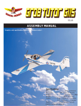
ASSEMBLY MANUAL
Specications:
Wingspan--------------- 66.9 in (170.0 cm).
Wing area--------------- 761.1 sq.ins (49.1 sq.dm).
Weight------------------- 9.3 lbs (4.2 kg).
Length------------------- 51.1 in (129.8 cm).
Engine ------------------ 0.75 - 0.91 cu.in----2 stroke.
---------------------------- 0.91- 1.00 cu.in----4 stroke.
Radio--------------------- 6 channels with 8 servos.
Retracts landing gear (included).
Electric conversion : optional
Code : SEA123K

ZERO KIT
2
Instruction Manual.
- Here is a list of supplies you should have on hand while you are building. Some of these are optional. Use
your own experience to decide what you need.
- Congratulations and thank you for purchasing the ZERO KIT. We are pleased to bring you this scale
ZERO KIT with this kit you can achieve whatever level of detail you like. Just by following the instruction
and nishing the plane in scale-looking trim scheme, beginning scale modelers will end up with a model
that very much represents and full-size ZERO KIT. Experienced builders will nd ways to add even more
detail, making the ZERO KIT competive in scale contents.
Getting prepare to build as:
- Flat Iron
- White Glue
- CA Glue
- Epoxy Glue
- Ruler
- Cutter Knife.
- Sandpaper Bar
- Aluminium Square Fixed Tool
INTRODUCTION
GETTING PREPARED FOR BUILDING
1.

3

ZERO KIT
4
Instruction Manual.

5

ZERO KIT
6
Instruction Manual.

7

ZERO KIT
8
Instruction Manual.

9
BUILD THE FUSELAGE
1.
2.
3.
4.
5.
- Firewall ( 3pcs).
- Fill White Glue to the surface of the F1B.
- Put the F1A on F1B to paste them together and
then ll White Glue on the surface of F1A.
- Put the F1 on F1A, F1B to paste them together
and then ll Epoxy Glue around block include 3
layers rewall.
- Attach M4 blind nut ( 4pcs) to block of rewall .
6.
7.

ZERO KIT
10
Instruction Manual.
8 .
9.
10.
11.
12.
13.
- Attach the ring F34 ( 2 pcs) to block of rewall
so that supporting keep fuel tank stopper.
- Put former F2 on the right fuselage side S2’.
- Using the ruler to adjust perpendicular angle of
former F2 and the right fuselage side S2.
- Fill CA Glue to keep xed F1, F2 with the fuselage
side S1 and S2.
- Arrange the le fuselage side S1 and the right fu-
selage side S2 as photo for dierence inside surface
and outside surface.
- Install rewall block with the right fuselage side
S2 by Epoxy Glude.
Please kindly see in the drawing sheet so that
avoiding mistake at this step.

11
14.
16.
17.
15.
19.
18.
- Fill CA Glue to keep xed F3 with the fuselage
side S1 and S2.
- Fill CA Glue to keep xed F5A (2pcs) with the
fuselage side S1, S2.
- Fill CA Glue to keep xed F5 with the fuselage
side S1 and S2 and F24.
- Fill CA Glue to keep xed F6 with the fuselage
side S1 and S2, and then paste F6A on F6 at two
side, and also install them to S1 and S2.
- Fill CA Glue to keep xed F4 with the fuselage
side S1 and S2.
- Fill CA Glue to keep xed F24 with F1, F2, F3,
F4, S1, S2.

ZERO KIT
12
Instruction Manual.
21 .
22.
23.
24.
25.
26.
20.
- Fill Epoxy Glue around block include two layers
F6, F6A.
Continue to former F7 to F11 as the instruction
photos below.(photo 21-25)

13
28.
27.
31.
30.
29.
- Using White Glue to paste former F12A, F12B
and F12 ( 2pcs) and then ll Epoxy Glue around
block.
- Attach M3 blind nut ( 4pcs) to block of F12 , add
thin White Glue.
- Fill CA Glue to keep xed block of F12 with the
fuselage side S1 and S2.
- Getting prepare for block include F14, F17, F18.
32.

ZERO KIT
14
Instruction Manual.
33.
34.
35.
36.
37.
38.
- Install block at the end of fuselage by CA Glue. - Install F13, F16, F19 together by CA Glue.
- Fill CA Glue to keep the contact face with rudder
at the end of fuselage.
- Fill CA Glue to keep xed block at the end of fu-
selage.
- Getting prepare for the contact face with rudder
include F13, F16, F19.

15
39.
40.
41.
42.
43.
- Install F2B at two side of fuselage by CA Glue. - Fill CA Glue to keep xed SW1 at lelf side of fu-
selage, SW2 at right side of fuselage.
- Getting prepare the mount of bottom hatch in-
clude F32 ( 2pcs).
- Paste two F32 together by Epoxy Glue.
- Install F33 at two side of fuselage by CA Glue.
44.

ZERO KIT
16
Instruction Manual.
48.
46.
49.
47. 50.
45.
- Attach M3 blind nut ( 2pcs) to block F32. - Fill CA Glue to keep xed the bottom plate F25
at head of fuselage where for engine.
- Attach the ring of wing nylon bolt F27 and F29 at
two side of fuselage by Epoxy Glue.
- Attach the ring of wing joiner tube F26 at two
side of fuselage by Epoxy Glue.
- Upside down block F32 and add White Glue at
M3 blind nut position.
- Fill CA Glue to keep xed block F32 with fuse-
lage ( Upside down fuselage so that installing F32
as photo).

17
51.
52.
53.
54.
55.
- Install F31 at two side of fuselage by Epoxy Glue. - Paste F21A on F21 by Epoxy Glue.
- Attach M3 blind nut to string of stick for antenna
F21 as photo.
- Install string of stick F21 for antenna at the top of
fuselage by CA Glue.
- Install string of stick F20 at the top of fuselage by
Epoxy Glue.
- Getting prepare string of stick for antenna in-
clude string of stick F21, the ring F21A and M3
blind nut.
56.

ZERO KIT
18
Instruction Manual.
57.
58.
60.
59.
62.
61.
- Install string of stick F21 at the bottom of fuse-
lage by CA Glue.
- Getting prepare for the latch of servo mount in-
clude FS2A (2pcs).
- Paste two latch FS2A together by Epoxy Glue.
- Attach M4 blind nut to the latch.
- Getting prepare for mounting plate of battery in-
clude the ring F28, M4 blind nut.
- Attach M4 blind nut to F28, and then paste them
on F24 at holes position where put M4 inox bolt by
Epoxy Glue.

19
63.
64.
65.
66.
67.
- Install the latch to le side of fuselage by Epoxy
Glue as photo.
- Using Aluminium Square Fixed Tool to go
through all formers at the square hole on each for-
mer.
- Paste F23 ( 2pcs) on the le side and right side
of fuselage by CA Glue to support for putting the
stabilizer.
- Install F15 to fuselage by CA Glue.
- Install 4x4 stringers by Epoxy Glue.
68.

ZERO KIT
20
Instruction Manual.
69.
2.
70.
3.
1.
- Getting prepare for push rod include plastic tube
( 3pcs) with Ø = 5mm.
- Install the plastic tube to go through all formers
which have path of Fin and path of Elevator hole
on each former and ll White Glue to keep xed.
- Cover the sheet SH1 on ribs of fuselage at the le
side, and then SH2 on ribs of fuselage at the right
side by CA Glue.
Please kindly see in the drawing sheet so that
avoiding mistake at this step.
If the balsa sheet quite hard, we should use the
wet towel so that making so the balsa sheet.
SHEETING FOR RIBS OF FUSELAGE
/