MAGNUM FIRST M9-UTR-L3 Installation guide

Type
Installation guide

MAGNUM FIRST M9-UTR-L3 is a versatile lighting control module that offers precise control and dimming of LED drivers, fluorescent ballasts, or switchable loads. It features bi-directional communication, enabling ON/OFF and 0-10V dimming control. The device can be paired with compatible EnOcean wireless devices, such as light switches or occupancy sensors, for various lighting applications. Additionally, it supports occupancy-based setback dimming and self-contained daylight harvesting functions, enhancing energy efficiency.

MAGNUM FIRST M9-UTR-L3 is a versatile lighting control module that offers precise control and dimming of LED drivers, fluorescent ballasts, or switchable loads. It features bi-directional communication, enabling ON/OFF and 0-10V dimming control. The device can be paired with compatible EnOcean wireless devices, such as light switches or occupancy sensors, for various lighting applications. Additionally, it supports occupancy-based setback dimming and self-contained daylight harvesting functions, enhancing energy efficiency.

1
Magnum First - 1930 Baseline Road, Grand Island, NY 14072 - phone 716-293-1588 - www.magnumfirst.com - [email protected]
Product Installation Guide
Two Channel Lighting Control Module
(0-10V) M9-UTR-L3
1] Description
4] Equipment Needed for Installation
5] Planning for Installation
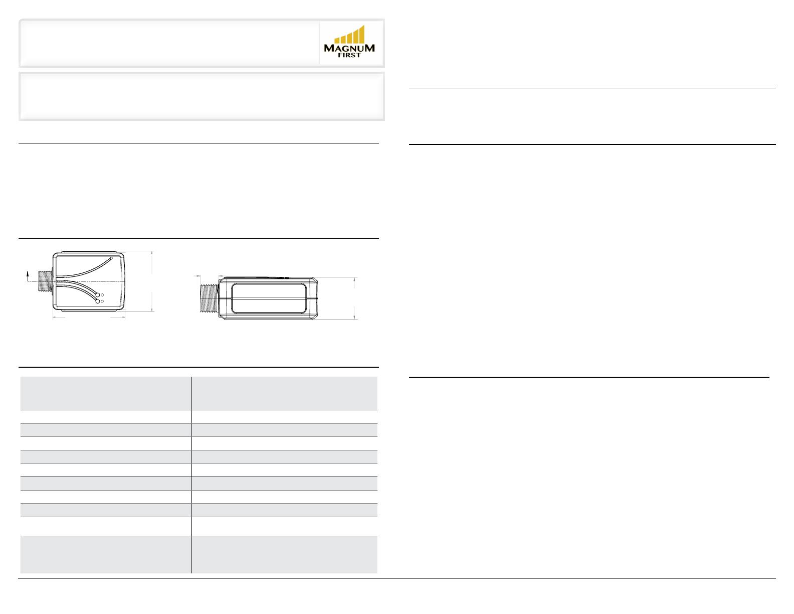
2] Dimensions
The Mx-UTR-L3 Lighting Control Module responds to a variety of wireless EnOcean devices to control and dim LED drivers,
fluorescent ballasts, or other switchable loads. The Mx-UTR-L3 oers bi-directional, ON/OFF and 0-10V dimming control when
combined with a wireless light switch or automatic shut-o when combined with a wireless occupancy sensor. Additionally,
the Lighting Control Module can perform occupancy-based setback dimming and self-contained daylight harvesting func-
tions. The Mx-UTR-L3 can be paired to compatible devices manually, and for more sophisticated configuration the MES
software airConfig tool is available for download at https://www.dropbox.com/s/mor2z812401nhti/airConfig_Setup.exe?dl=0
• Electrical tape • Screwdriver • Wire nuts
* For advanced configuration, additional equipment is required, including laptop, USB 300U (available for order from MES)
and AirConfig, which is available for free download at http://download.magnumes.net
• Take a moment to prepare for installation and ensure optimal communications with other system components in the
space
To assess signal strength prior to and during installation, you can utilize the following:
- MES’s free range testing tool “AirSpy”, aemail [email protected] for a copy of AirSpy
Requires USB 300U.
-If utilizing Mx-EBOXs (BACnet to IP) gateway, utilize BACnet point available for signal strength
(RSSI)
Always utilize a qualified installer
• Straighten antenna out and away from any surrounding metal
• Create separation distance between interfering electronics such as fluorescent tube ends, ballasts, electronic
transformers, and motors. Avoid mounting inside of metal enclosures.
• Obstructions of metal, concrete and dense building materials will reduce the range. Mount higher and away from
obstructions to maximize range.
In applications using HVAC units a Relay Contactor is required for the units per AMP rating.
If following the standard, manual pairing process, please refer to the “Learn In Procedure” section at the end of this
document. If manual with default settings is the preferred method of commissioning, it is recommended this process be
done prior to installation, unless access to buttons and device is possible.
For advanced configuration using AirConfig, install Mx-UTR-L3 as discussed and perform commissioning process with
device installed. Make sure that device is still within wireless range.
6] Installation
COMMON APPLICATIONS:
WARNING: TO AVOID RISK OF FIRE, SHOCK, OR DEATH, TURN OFF POWER AT CIRCUIT BREAKER OR FUSE AND
VERIFY THAT IT IS OFF BEFORE INSTALLATION BEGINS. MAKE SURE THAT IT REMAINS OFF UNTIL INSTALLA-
TION IS COMPLETE. PLEASE BE AWARE THAT WITH THIS VERSION OF THE PRODUCT, IT IS POSSIBLE TO HAVE
MULTIPLE BRANCH CIRCUITS FEEDING THE RELAY RECEIVER.
NOTE: Read the WARNINGS AND CAUTIONS section before beginning these installation options. Read all steps for this
option before taking any action to install receiver.
1) For in-wall installation, a wiring box must be used. For ceiling installation make wire connections inside a junction box.
Ensure that the temperature in the ceiling box will not exceed 50 degrees C. For best wireless signal performance install
receiver in plastic box away from floor and away from metal objects.
2) Connect wires as shown in Figure A. Twist wire nuts on clockwise making sure no bare wires show. Wrap connections
with electrical tape.
3) Stow all wires in wiring box.
4) Restore power and follow instructions under the “Setting Up Your Device via airConfig” section at the end of this
document, or follow manual pairing procedures to use default settings.
5) To test that the device is working, press and release SW1. This will toggle ON/OFF. (If receiver is not working, review
wiring and programming instructions).
6) Finish any installation of fixture or wall switch.
3] Technical Specifications:
Part Numbers (Frequency Dependant) M9-UTR-L3 (902 MHz - North America)
M8-UTR-L3 (868 MHz - Europe and China)
MJ-UTR-L3 (928 MHz - Japan)
Range 150 feet (50-150 typical)
EnOcean Profile (2x) A5-38-08 Type 0x02 Dimming
Input Voltage 120/277 VAC
Max Switched Power 3300W @ 277VAC
Max Switched Current 20A
Max Switched Voltage 120/277 VAC
Relay Output 2 N.O. and 2 Common contact
Dimmer Output (2x) 0-10V, 30 mA (sinking drivers)
Ambient Operating Temperature 0-55°C for 3300 W load @ 277 VAC
(Mx-UTR-L3 & Mx-UTR-L2: 37°C for 3300 W load @ 277 VAC)
Certifications ETL/Intertek - UL 244A
FCC (United States) SZV-TCM3XXX
IC (Canada) 5713A-TCMXXX
DLC
2.439
2.939
2.319
AA
R.563
R.320
.060
.060
73.74°
.071
2.26°
2.94°
.044
.049
.824
SECTION
A-A
1.250 .900
.550
D
C
B
A
A
B
C
D
1
2
3
4
5
6
7
8
8
7
6
5
4
3
2
1
THE INFORMATION CONTAINED IN THIS
DRAWING IS THE SOLE PROPERTY OF
<INSERT COMPANY NAME HERE>. ANY
REPRODUCTION IN PART OR AS A WHOLE
WITHOUT THE WRITTEN PERMISSION OF
<INSERT COMPANY NAME HERE> IS
PROHIBITED.
PROPRIETARY AND CONFIDENTIAL
NEXT ASSY
USED ON
APPLICATION
DIMENSIONS ARE IN INCHES
TOLERANCES:
FRACTIONAL
ANGULAR: MACH
BEND
TWO PLACE DECIMAL
THREE PLACE DECIMAL
INTERPRET GEOMETRIC
TOLERANCING PER:
MATERIAL
FINISH
DRAWN
CHECKED
ENG APPR.
MFG APPR.
Q.A.
COMMENTS:
DATE
NAME
TITLE:
SIZE
B
DWG. NO.
REV
WEIGHT:
SCALE: 1.25:1
UNLESS OTHERWISE SPECIFIED:
SHEET 1 OF 1
Relay 2-1
DO NOT SCALE DRAWING
2.939”
(74.65 mm)
2.319”
(58.9 mm)
2.439
2.939
2.319
AA
R.563
R.320
.060
.060
73.74°
.071
2.26°
2.94°
.044
.049
.824
SECTION
A-A
1.250
.900
.550
D
C
B
A
A
B
C
D
1
2
3
4
5
6
7
8
8
7
6
5
4
3
2
1
THE INFORMATION CONTAINED IN THIS
DRAWING IS THE SOLE PROPERTY OF
<INSERT COMPANY NAME HERE>. ANY
REPRODUCTION IN PART OR AS A WHOLE
WITHOUT THE WRITTEN PERMISSION OF
<INSERT COMPANY NAME HERE> IS
PROHIBITED.
PROPRIETARY AND CONFIDENTIAL
NEXT ASSY
USED ON
APPLICATION
DIMENSIONS ARE IN INCHES
TOLERANCES:
FRACTIONAL
ANGULAR: MACH
BEND
TWO PLACE DECIMAL
THREE PLACE DECIMAL
INTERPRET GEOMETRIC
TOLERANCING PER:
MATERIAL
FINISH
DRAWN
CHECKED
ENG APPR.
MFG APPR.
Q.A.
COMMENTS:
DATE
NAME
TITLE:
SIZE
B
DWG. NO.
REV
WEIGHT:
SCALE: 1.25:1
UNLESS OTHERWISE SPECIFIED:
SHEET 1 OF 1
Relay 2-1
DO NOT SCALE DRAWING
1.25”
(31.75 mm)
.55”
(13.97 mm)
2
Magnum First - 1930 Baseline Road, Grand Island, NY 14072 - phone 716-293-1588 - www.magnumfirst.com - [email protected]
Product Installation Guide
7] Wiring Diagrams 8] Wireless Mounting Options
9] Compatible Devices
10] Warnings & Cautions
FIGURE A: Single Power Source
FIGURE B: Dual Power Source
• The Mx-UTR-L3 can be controlled using a variety of other devices, including:
• Mx-ML2 (Occ / Lux Sensor) • Mx-EOSC (Ceiling Mounted Occ Sensor)
• Mx-EOSW (Wall Mounted Occ Sensor) • Mx-SW1 (Wireless Single Rocker Switch)
• Mx-SW2 (Wireless Double Rocker Switch) • Mx-ESRP (Wireless Single Rocker Switch)
• Mx-EDRP (Wireless Double Rocker Switch) • Mx-MRC1 (Wireless Window / Door Sensor)
• Mx-EDWS (Wireless Window / Door Sensor) • Mx-ECKU (Wireless Key Card Switch)
• Mx-eBox (BACnet IP Gateway) • Mx-AP2 (Access Point)
• HIGH VOLTAGE: A qualified installer or electrician must install this device. Follow all applicable electrical codes for installation.
• Relays and receivers are intended for INDOOR use only, in dry locations with permanently installed fixtures
• This device is suitable for a circuit capable of delivering not more than 20 AMP maximum
• Be sure not to install this device in locations where the units are in close proximity to the light bulbs or other sources of
heat, particularly with high wattage loads.
• When using relays to switch a motor, overload and over current protection sized for the motor load should be provided at
the branch circuit feeder supplying the motor in accordance with the NEC or CEC, as applicable for the installation location
• The maximum over current protection required for the branch circuit supplying this product is 20 AMPS. When one or
more motors are installed and not internally protected then an overload protective device sized at not more than 115% of the
motor full load AMPS should be installed for each motor.
• When using devices to control motors and HVAC equipment, which don’t respond well to the ON/OFF cycling that occurs
in the “learn” mode, it is advised to configure the receivers without the motor or HVAC load connected. Instead, program the
products in advance by connecting them to a light or to another load that is safe when toggling on and o.
OUTSIDE JUNCTION BOX
THREADED
WIRELESS
RELAY
JUNCTION BOX
2.439
2.939
2.319
AA
R.563
R.320
.060
.060
73.74°
.071
2.26°
2.94°
.044
.049
.824
SECTION
A-A
1.250 .900
.550
D
C
B
A
A
B
C
D
1
2
3
4
5
6
7
8
8
7
6
5
4
3
2
1
THE INFORMATION CONTAINED IN THIS
DRAWING IS THE SOLE PROPERTY OF
<INSERT COMPANY NAME HERE>. ANY
REPRODUCTION IN PART OR AS A WHOLE
WITHOUT THE WRITTEN PERMISSION OF
<INSERT COMPANY NAME HERE> IS
PROHIBITED.
PROPRIETARY AND CONFIDENTIAL
NEXT ASSY
USED ON
APPLICATION
DIMENSIONS ARE IN INCHES
TOLERANCES:
FRACTIONAL
ANGULAR: MACH
BEND
TWO PLACE DECIMAL
THREE PLACE DECIMAL
INTERPRET GEOMETRIC
TOLERANCING PER:
MATERIAL
FINISH
DRAWN
CHECKED
ENG APPR.
MFG APPR.
Q.A.
COMMENTS:
DATE
NAME
TITLE:
SIZE
B
DWG. NO.
REV
WEIGHT:
SCALE: 1.25:1
UNLESS OTHERWISE SPECIFIED:
SHEET 1 OF 1
Relay 2-1
DO NOT SCALE DRAWING
BREAKER PANEL
HOT BLACK
AC POWER BLACK
AC POWER WHITE
LIGHT
FIXTURES
GROUND GREEN
RELAY 2:
BLUE WITH RED STRIPE
RELAY 1:
BLUE WITH BLACK STRIPE
RELAY 2:
RED WITH GREY STRIPE
RELAY 1:
BLACK WITH BLUE STRIPE
AC POWER IN
BLACK
0-10 V OUTPUT: GREY (-)
0-10 V OUTPUT: GREY WITH RED STRIPE (-)
0-10 V OUTPUT: VIOLET (+)
0-10 V OUTPUT: VIOLET WITH RED STRIPE (+)
AC POWER IN
WHITE
WIRELESS CONTROL
SIGNAL UP TO 150 FT
BATTERY-FREE
WIRELESS SWITCHES
NEUTRAL WHITE
GROUND
GREEN
MX-UTR-L3
2.439
2.939
2.319
AA
R.563
R.320
.060
.060
73.74°
.071
2.26°
2.94°
.044
.049
.824
SECTION
A-A
1.250 .900
.550
D
C
B
A
A
B
C
D
1
2
3
4
5
6
7
8
8
7
6
5
4
3
2
1
THE INFORMATION CONTAINED IN THIS
DRAWING IS THE SOLE PROPERTY OF
<INSERT COMPANY NAME HERE>. ANY
REPRODUCTION IN PART OR AS A WHOLE
WITHOUT THE WRITTEN PERMISSION OF
<INSERT COMPANY NAME HERE> IS
PROHIBITED.
PROPRIETARY AND CONFIDENTIAL
NEXT ASSY
USED ON
APPLICATION
DIMENSIONS ARE IN INCHES
TOLERANCES:
FRACTIONAL
ANGULAR: MACH
BEND
TWO PLACE DECIMAL
THREE PLACE DECIMAL
INTERPRET GEOMETRIC
TOLERANCING PER:
MATERIAL
FINISH
DRAWN
CHECKED
ENG APPR.
MFG APPR.
Q.A.
COMMENTS:
DATE
NAME
TITLE:
SIZE
B
DWG. NO.
REV
WEIGHT:
SCALE: 1.25:1
UNLESS OTHERWISE SPECIFIED:
SHEET 1 OF 1
Relay 2-1
DO NOT SCALE DRAWING
BREAKER PANEL
BREAKER PANEL
HOT BLACK
AC POWER BLACK
AC POWER WHITE
LIGHT
FIXTURES
GROUND GREEN
RELAY 2: BLUE WITH
RED STRIPE
RELAY 1: BLUE
WITH BLACK STRIPE
RELAY 2: RED WITH
GREY STRIPE
RELAY 1: BLACK
WITH BLUE STRIPE
AC POWER IN
BLACK
0-10 V OUTPUT: GREY (-)
0-10 V OUTPUT: GREY WITH RED STRIPE (-)
0-10 V OUTPUT: VIOLET (+)
0-10 V OUTPUT: VIOLET WITH RED STRIPE (+)
AC POWER IN
WHITE
WIRELESS CONTROL
SIGNAL UP TO 150 FT
BATTERY-FREE
WIRELESS SWITCHES
NEUTRAL WHITE
GROUND
GREEN
MX-UTR-L3
2.439
2.939
2.319
AA
R.563
R.320
.060
.060
73.74°
.071
2.26°
2.94°
.044
.049
.824
SECTION
A-A
1.250 .900
.550
D
C
B
A
A
B
C
D
1
2
3
4
5
6
7
8
8
7
6
5
4
3
2
1
THE INFORMATION CONTAINED IN THIS
DRAWING IS THE SOLE PROPERTY OF
<INSERT COMPANY NAME HERE>. ANY
REPRODUCTION IN PART OR AS A WHOLE
WITHOUT THE WRITTEN PERMISSION OF
<INSERT COMPANY NAME HERE> IS
PROHIBITED.
PROPRIETARY AND CONFIDENTIAL
NEXT ASSY
USED ON
APPLICATION
DIMENSIONS ARE IN INCHES
TOLERANCES:
FRACTIONAL
ANGULAR: MACH
BEND
TWO PLACE DECIMAL
THREE PLACE DECIMAL
INTERPRET GEOMETRIC
TOLERANCING PER:
MATERIAL
FINISH
DRAWN
CHECKED
ENG APPR.
MFG APPR.
Q.A.
COMMENTS:
DATE
NAME
TITLE:
SIZE
B
DWG. NO.
REV
WEIGHT:
SCALE: 1.25:1
UNLESS OTHERWISE SPECIFIED:
SHEET 1 OF 1
Relay 2-1
DO NOT SCALE DRAWING
NOTE: Magnum Wireless device antenna cannot be
enclosed inside a metal box. Wireless range will be
greatly limited with enclosed antenna.
3
Magnum First - 1930 Baseline Road, Grand Island, NY 14072 - phone 716-293-1588 - www.magnumfirst.com - [email protected]
12] Setting Up Your Device Via airConfig
13] Advance Features Customizable via airConfig
Step One
Download airConfig™, based on your operating system, to your computer at https://www.dropbox.com/s/
mor2z812401nhti/airConfig_Setup.exe?dl=0
Step Two
• Insert Magnum Innovations provided USB stick into your computer
Step Three
• Power up your device
Step Four
• Your laptop / computer (with provided USB stick) must be within radio range to configure device
Step Five
• Start airConfig™ and select “Advanced” tab
11] Learn In Procedure 11] Learn In Procedure (continued)
It is important to mention that MES devices utilize a point to point wireless topology. The devices are meant to respond
only to those devices that they have been paired with, eectively ignoring all other devices. This allows for many devices
to be in the same space controlling a variety of dierent applications without cross-talk. The process outlined below is for
manually pairing the Mx-UTR-L3 to compatible devices. Once complete, this device will only respond to the compatible
devices you physically pair it with. Whether BASIC or ADVANCED is preferred, you can always use airConfig via a USB300U
with airConfig downloaded at https://www.dropbox.com/s/mor2z812401nhti/airConfig_Setup.exe?dl=0. See “Setting Up
Your Device Via airConfig” at the end of this document.
1. To enter Learn Mode, press and hold SW1 for 5 seconds (Use non-metallic pin):
A) Both LEDs flash, then LED1 begins to blink indicating learn mode is active
2. Learning Devices:
A) To learn a Light Switch or Key Card,Press ON (Up) Light Switch 3 times quickly (within 3 seconds)
For Key Card, insert card into reader 3 times quickly (withing 3 seconds)
i) LED1 goes solid for 2 seconds, indicating the switch is learned
ii) LED1 then begins to blink indicating it has returned to learn mode for the next pairing
B) If there are more switches to learn in, repeat step A
C) To learn an Occupancy Sensor, press the learn button on the Occupancy Sensor
i) LED1 goes solid for 2 seconds, indicating the switch is learned
ii) LED1 then begins to blink indicating it has returned to learn mode for the next pairing
D) To learn a Door Sensor, press the learn button on the Door Sensor while the contact is open
i) LED1 goes solid for 2 seconds, indicating the switch is learned
ii) LED1 then begins to blink indicating it has returned to learn mode for the next pairing
E) IF ALL DESIRED DEVICE ARE LEARNED-IN, PRESS SW1 TO END LEARN MODE
i) LED1 goes solid for 2 seconds
ii) LED1 turns o
F) PRESS SW2 TO EXIT LEARN MODE
i) LED2 goes solid for 2 seconds
ii) LED2 turns o
iii) Both LEDs flash indicating it has returned to Operational Mode
3. Clear All: NOTE: this removes all paired devices from memory and cannot be undone.
A) Press and hold both SW1 and SW2 simultaneously for 10 seconds
B) LED1 LED2 both begin to flash
C) Press both SW1 and SW2 again within 10 seconds to clear all
i) Without a press within those 10 seconds, the relay will return to normal operation and cancel clear all
D) Once cleared, LED1 and LED2 will go solid and relay will turn OFF
E) Relay will remain in the o state since no IDs learned in to control it
F) Verify Clear all by pressing Switch without toggling ON/OFF state of Relay
Verify Clear all by pressing Learn Button on Occupancy Sensor and LEDs do not blink
Please repeat the “Clear All” process if the Switch or Occupancy Sensor is not cleared.
MES oers two dierent options for pairing devices and customizing settings. For more advanced configuration, airConfig
is a free software tool provided by MES. The download is free via http://download.magnum-innovations.net and requires
a USB stick (ordered from MES) and a laptop. Once the advanced configuration is completed, the laptop and USB are no
longer needed for operation. The configuration settings are stored in the products that remain on site.
Airconfig is a free software provided by Magnum specifically for the advanced configuration of devices. It uses a USB stick
and a laptop to communicate with the relays and sensors and deliver their new instructions. Once the advanced configuration
is complete the laptop and USB are no longer needed and the configuration will be stored in the products remaining on site.
Product Installation Guide
SWITCH KEY CARDRELAY
LED2
LED1 ON
OFF
SW1
SW2
Always have
LEDs and SWs
accessible upon
installation.
• Ability to activate built in PI loop controller
• Customizable dimming table for advanced daylighting control settings
• Ability to select Mx-UTR-L3 as either Level 1 or Level 2 repeater
• Enable or disable the “occupancy auto on” feature
• Change ON/OFF timers associated with paired devices i.e. occupancy sensor, window/door contact and rocker switch
• Adjustable ramping speed allows for advanced settings with rate of dim
• Adjust the minimum and maximum voltage provided to fixtures
• Changeable voltage settings
• Selectable options for behavior after power loss
• Customize unoccupied light value
• Select the light “on” value to previous value or background daylighting control
• Advanced scene control allows for up to 4 scenes with user selectable percentages
READER
4
Magnum First - 1930 Baseline Road, Grand Island, NY 14072 - phone 716-293-1588 - www.magnumfirst.com - [email protected]
Product Installation Guide
14] Ideal Product Placement 14] Ideal Product Placement: (continued)
Better:
Receiver inside and antenna
outside.
Better:
Maximize separation distance
(between wireless receiver
and ballast) and pull antenna
outside of fixture.
Worst Case:
Antenna and receiver inside
metal box
Worst Case:
Wireless receiver and
antenna next to ballast or in
“Keep Out” zones.
Best:
Receiver and antenna outside. Best:
Avoid placing wireless receiver
and antenna within 6” of tube
sockets
Best:
Outside of fixture and away from “Keep Out”
zones and ballasts
Best:
Outside of fixture and away from “Keep Out”
zones and ballasts
Better:
Receiver inside and antenna
outside.
Worst Case:
Antenna and receiver inside
J-Box
Junction Boxes
Utility Boxes / Relay Panels
Best:
Receiver and antenna outside.
Create separation distance away from interfering electronics
Fluorescent Lighting Ballasts
Fluorescent Light Fixtures
Lighting
Best:
Antenna and receiver on top or bottom (if ceiling
is non-metal)
Best:
Antenna and receiver on top or bottom (if ceiling
is non-metal)
HVAC Ducts
HVAC - PTAC Units
15] Wireless Range Reducers
16] Wireless Range Testing
Wood, drywall, glass (uncoated, without metal) 0-10%
Brick, particle board 5-35%
Metal, ferro concrete, mirrors 10-90%
Site survey tools are available that can help fine-tune wireless communications. For example:
- Indicates wireless signal strength
- Evaluate longer range scenarios that might require enabling repeaters.
Please email info@magnumfirst.com or call 716 293-1588 to order a USB300U and to request a free download of
AirSpy, Magnum’s wireless signal testing tool.
5
Magnum First - 1930 Baseline Road, Grand Island, NY 14072 - phone 716-293-1588 - www.magnumfirst.com - [email protected]
Product Installation Guide
17] Troubleshooting
18] Warranty
PROBLEM WHAT TO CHECK
Lamps/luminaires do not dim Make sure the ballast is compatible with 0-10V dim-
ming. If the ballast is dimmable, yet the light does not
dim, check to ensure the Mx-UTR-L3 was wired properly
and that the 0-10V output is also wired correctly.
Lighting load doesn’t switch ON/OFF Check to be sure connections to Lighting Control
Module comply with the technical specifications listed
on this document.
The wrong lights are being controlled Be sure to review the “Learn in Procedure” and the
“Setting Up Your Device via airConfig” to be sure that
you paired the device correctly to the selected,
compatible device(s). To test the device, please press
and release SW1. The connected load will toggle ON/
OFF.
U.S. Two-year Limited Warranty: Products purchased in the U.S.A. are warranted for two years from date of
purchase by Magnum Innovations to be free of defects in materials and workmanship. In the event of such
defect, product will be repaired promptly without charge or, at our option, replaced with a new product of
equal or superior value if delivered to Magnum or an Authorized Service Center, prepaid, together with
the sales slip or other proof of purchase date. This warranty excludes defects due to normal wear, abuse,
shipping damage, or failure to use product in accordance with instructions. This warranty is void in the
event of unauthorized repair or modification, or removal or defacing of the product labeling. The Magnum
warranty specified herein covers material only and does not include labor or incidental costs associated with
product replacement or repair.
  • Page 1 1
  • Page 2 2
  • Page 3 3
  • Page 4 4
  • Page 5 5

MAGNUM FIRST M9-UTR-L3 Installation guide

Type
Installation guide

MAGNUM FIRST M9-UTR-L3 is a versatile lighting control module that offers precise control and dimming of LED drivers, fluorescent ballasts, or switchable loads. It features bi-directional communication, enabling ON/OFF and 0-10V dimming control. The device can be paired with compatible EnOcean wireless devices, such as light switches or occupancy sensors, for various lighting applications. Additionally, it supports occupancy-based setback dimming and self-contained daylight harvesting functions, enhancing energy efficiency.

Ask a question and I''ll find the answer in the document

Finding information in a document is now easier with AI