cantaloupe ePort G9 User manual

Type
User manual

Cantaloupe ePort G9 is a cashless payment system that can be installed into TouchTunes Entertainment Systems, allowing customers to make purchases using cards instead of cash. It comes with a card reader, a telemeter, and various cables for interfacing with different TouchTunes machine models. The system also includes an antenna for wireless communication, enabling remote monitoring and management of transactions.

Cantaloupe ePort G9 is a cashless payment system that can be installed into TouchTunes Entertainment Systems, allowing customers to make purchases using cards instead of cash. It comes with a card reader, a telemeter, and various cables for interfacing with different TouchTunes machine models. The system also includes an antenna for wireless communication, enabling remote monitoring and management of transactions.

Installing The USA Technologies Cashless Solution
into TouchTunes Entertainment Systems
TOOLS REQUIRED FOR INSTALLATION
11/32” Socket
1/4” Socket
12” Extension
Ratchet
Phillips Screwdriver
Wire Cutters
Power Drill*
3/16” & 3/8” Drill Bit*
Multi-diameter Step Drill Bit,
1/4”-3/4”*
#VXXUDTUN1900
This Installation Guide should be used to install the USA Technologies ePort
G9 into all of the designated Touch Tunes Entertainment systems. Please re-
and to familiarize yourself with the installation processes.
ePort G9 TelemeterePort G9 Card Reader
CANTALOUPE
CABLES TO INTERFACE TO MX-1 MACHINES
WITHOUT COIN ACCEPTOR
Kit: #VVVUTTUN1232
ePort Interface Cable: #VXXUC0101301
ePort Interface Cable: #VXXUC0101303
WITH COIN ACCEPTOR
Kit: #VVWUTTUN1232
ePort Interface Cable: #VXXUC0101303
Machine Interface Cable: #300200-008
Machine Interface Cable: #300987-006
USAT adapter 1: #300982
USAT adapter 3: #300986
INSTALLATION PROCEDURES
Each kit is shipped with an ePort G9 Telemeter and card reader, installation hardware, tie-wraps, and Velcro to mount
the ePort cashless payment system. However, each kit has specic cable(s) required to interface the ePort to the spe-
cic machine you are modifying. Please use the tables and illustrations below to ensure you have the correct material
in the kit that was shipped to you by USA Technologies.
1
CABLES TO INTERFACE TO VIRTUO AND OVATION II MACHINES
WITHOUT COIN ACCEPTOR
Kit: #VVVUTTUN1230
ePort Interface Cable: #VXXUC0101301
WITH COIN ACCEPTOR
Kit: #VVWUTTUN1230
ePort Interface Cable: #VXXUC0101303
Machine Interface Cable: #300200-008
USAT adapter 1: #300982
CABLES TO INTERFACE TO ALLEGRO AND OVATION I MACHINES
WITHOUT COIN ACCEPTOR
Kit: #VVVUTTUN1233
ePort Interface Cable: #VXXUC0101303
WITH COIN ACCEPTOR
Kit: #VVWUTTUN1233
ePort Interface Cable: #VXXUC0101303
Machine Interface Cable: #300987-006
USAT adapter 3: #300986
2
CABLES TO INTERFACE TO PLAYDIUM MACHINES
WITHOUT COIN ACCEPTOR
Kit: #VVVUTTUN1231
ePort Interface Cable: #VXXUC0101302
WITH COIN ACCEPTOR
Kit: #VVWUTTUN1231
ePort Interface Cable: #VXXUC0101303
Machine Interface Cable: #300988-006
USAT adapter 2: #300984
PREPARING THE EPORT G9 FOR INSTALLATION
1. Remove the ePort G9 Telemeter and Card Reader from the box.
2. Insert the 4 supplied set-screws into the back of the card read-
er, and  rmly tighten with the supplied hex-wrench.
3. Connect the white connector of the cable shown in FIG. 1 to its
mating connector in the back of the card reader.
4. Plug the metal connector at the end of one cable from the
Telemeter into the round connector designated by the “HAND
HELD DEX” on the front label.
5. Attached supplied black velcro strips to back of the Telemeter.
6. Set the G9 Telemeter, card reader, and antenna off to the side.
MOUNTING THE EPORT G9 CARD READER IN OVATION I AND OVATION II MACHINES
ATTENTION: This kit requires a new Lexan cover for the front of the machine.
Please contact your TouchTunes Sales Rep at 1-847-419-3300.
1. Remove power from the entertainment system.
2. Remove the USB connection of the existing card reader from the computer.
3. Remove the existing card reader from the front door
4. Install the new Lexan label (FIG. 2) over the existing front of the system (FIG. 3).
5. From page 8 choose, then cut out the correct drill template to use.
6. Apply the drill template over the Lexan label as shown in FIG. 4 or FIG 5.
7. Using a 3/16th inch drill bit, drill the 4 mounting holes, and a pilot hole for the larg-
er hole in the middle.
8. Using a ½ inch drill bit, drill the piloted large hole.
9. Remove the drill template, and pass the black connector of the card reader through
the ½ inch drilled hole.
FIG. 1
FIG. 2
FIG. 3
3
10. Align the four set-screws in the back of the card
reader to the 3/16th inch holes, and mount the
card reader to the front panel of the system with
the four supplied nuts (FIG. 6). It may be nec-
essary to use the large  at washers to catch the
sides of the front panel (FIG. 7).
11. Mount and attach the G9 Telemeter inside the
Ovation as shown in FIG. 8 with the other half of
the supplied black velcro strips.
12. Route antenna cable through the back of the
upper portion of the system. The antenna has
a magnetic base that will secure it to any metal
surface. If there is no metal surface within reach, use the Velcro buttons supplied to mount to any surface.
MOUNTING THE EPORT G9 CARD READER IN A PLAYDIUM MACHINE
1. Remove power from the system.
2. Remove the 2 backlight connectors for the credit
card reader shown by the arrows in FIG. 9. Po-
sition the wires out of the way so they are not
damaged when drilling.
3. Place the supplied self-adhering drill template on
the outside of the system so that the cross-hair of
the large drill hole in the center of the template is
centered over the middle of the card reader slot
of the front panel (FIG. 10).
4. Using a 3/16th inch drill bit, drill the 4 mounting
holes, and a pilot hole for the larger hole in the
middle.
5. Using a ½ inch drill bit, drill the piloted large hole
through the plastic credit card slot in the panel.
The drill should exit directly below the existing
card reader mounted on the inside. See the
arrow in FIG. 11.
6. Pass the black connector of the card reader
through the ½ inch drilled hole.
7. Align the four set-screws in the back of the card
reader to the 3/16th inch holes, and mount the
card reader to the front panel of the system with
the four supplied nuts.
8. Mount the G9 Telemeter inside the Playdium as shown in FIG. 12 with other half of the supplied black Velcro strips.
9. Route antenna cable through the back of the upper portion of the system. Remove the lower right strain relief, and
bring antenna wire up alongside the Playdium. The antenna has a magnetic base that will secure it to any metal
surface. If there is no metal surface within reach, use the Velcro buttons supplied to mount to any surface.
10. Reconnect backlight connectors that were removed in step 2.
FIG. 4 FIG. 5
FIG. 6 FIG. 8
FIG. 7
FIG. 9
FIG. 10 FIG. 11 FIG. 12
4
MOUNTING THE EPORT G9 CARD READER IN A MX-1 MACHINE
ATTENTION: This kit requires a new Lexan cover for the front of the machine.
Please contact your TouchTunes Sales Rep at 1-847-419-3300.
1. Remove power from the entertainment system.
2. Remove the USB connection of the existing card from the computer board.
3. Remove the existing card reader from the front door
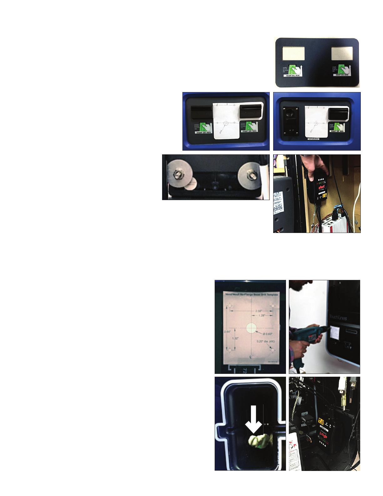
4. Install the new Lexan label (FIG. 13) on the front of the system.
5. From page 8 choose, then cut out and use the cor-
rect drill template.
6. Apply the drill template over top the recently in-
stalled Lexan label as shown in FIG. 14 or FIG. 15.
7. Using a 3/16th inch drill bit, drill the 4 mounting
holes, and a pilot hole for the large, center hole.
8. Using a ½ inch drill bit, drill the piloted large hole.
9. Pass the black connector of the card reader
through the ½ inch drilled hole.
10. Align the four set-screws in the back of the
card reader to the 3/16th inch holes, and
mount the card reader to the front panel
of the system with the four supplied nuts.
It may be necessary to use the large  at
washers to catch the sides of the front panel (FIG. 16).
11. Mount and attach the Telemeter inside the MX-1 as shown in FIG. 17 with the oth-
er half of the supplied black velcro strips.
12. Route antenna cable through the back of the upper portion of the system, and
attach antenna to system. The antenna has a magnetic base that will secure it to any metal surface. If there is no
metal surface within reach, use the Velcro buttons supplied to mount to any surface.
MOUNTING THE EPORT G9 CARD READER IN VIRTUO MACHINES
1. Remove power from the entertainment system.
2. Remove the USB connection of the existing card from the
computer board.
3. Place the supplied self-adhering drill template on the outside
of the system so that the template completely covers the white
outline of the card reader slot (FIG. 18).
4. Using a 3/16th inch drill bit, drill the 4 mounting holes, and a
pilot hole for the larger hole in the middle (FIG. 19).
5. Using a ½ inch drill bit, drill the piloted large hole through the
plastic credit card slot in the panel. The drill should exit direct-
ly below the existing card reader mounted on the inside. See
the arrow in FIG. 20.
6. Pass the card reader’s black connector through the ½ inch hole.
7. Align the four set-screws in the back of the card reader to the
3/16th inch holes, and mount the card reader to the front pan-
el of the system with the four supplied nuts.
8. Mount and attach the Telemeter inside the Virtuo as shown in
FIG. 21 with the other half of the supplied black velcro strips.
9. Route antenna cable through the back of the upper portion
of the system. Remove the lower right strain relief, and bring
antenna wire up alongside the Playdium. The antenna has a
magnetic base that will secure it to any metal surface. If there
is no metal surface within reach, use the Velcro buttons sup-
plied to mount to any surface.
FIG. 13
FIG. 14 FIG. 15
FIG. 16 FIG. 17
FIG. 18 FIG. 19
FIG. 20 FIG. 21
5
CONNECTING THE EPORT G9 TELEMETER TO THE CARD READER
Antenna
Below the ANTENNA designation on the label of the Tele-
meter, is a round connector. Insert the round connector
at the end of the antenna wire into this connector until it
clicks”. It is important to leave the antenna wire unbounded
and hanging loosely for best reception.
Connecting the ePort G9 to the card reader
Of the three cables coming from the Telemeter, the cable
with the small black connector is used to connect to the card
reader. Insert the card readers black connector into the con-
nector of the Telemeter until seated  rmly. The connection is
shown in FIG. 22.
Connecting the ePort G9 to the TouchTunes Interface Cable
The interface cable that connects the ePort G9 Telemeter to the TouchTunes en-
tertainment system is a gray cable with three connectors on it; two connectors at
one end, and a single connector at the other. The end with the two connectors
is used to connect to the ePort G9. The white connector on the interface cable
connects to a white mating connector on one of the cables coming from the
ePort G9 Telemeter. The black connector on the interface cable connects to the
Auxiliary Port of the ePort G9 Telemeter which is located below the AUX” desig-
nation on the label of the ePort G9 telemeter. See FIG. 23.
CONNECTING THE INTERFACE CABLE TO THE TOUCHTUNES SYSTEM WITH NO COIN ACCEPTOR
Virtuo and Ovation II systems
Virtuo and Ovation II systems will have a
white connector located on the door as
shown in FIG. 24. Connect the white con-
nector at the end of the interface cable to
the white connector on the systems door.
Most MX-1 systems
Most MX-1 systems, have a white con-
nector on their door as shown in FIG. 25.
Connect the white connector at the end of
the interface cable to the white connector
on the systems door.
Playdium systems
The interface cable connects to the Play-
diums backplane to the white connector
shown in FIG. 26 labeled COIN ACC.
Allegro and Ovation I systems
The Gen 3 systems have an IO Board that
uses the Coin Acceptor connection. See
FIG 27 and 28 for location. Connect the
black connector at the end of the interface
cable to the black connector on the IO
board.
FIG. 23
FIG. 22
FIG. 24 FIG. 25
FIG. 26
FIG. 27
FIG. 28
6
CONNECTING THE INTERFACE CABLE TO THE TOUCHTUNES SYSTEM WITH A COIN ACCEPTOR
If the TouchTunes entertainment system has a Coin Acceptor, then the following instructions should be used to prop-
erly connect the ePort G9 Telemeter. Entertainment systems with Coin Acceptors require an additional Adapter Board
and cable. Please refer to the tables at the beginning of this document for the proper cables and adapter boards.
Follow the instructions below for the TouchTunes system that you have.
Virtuo, Ovation II, MX-1 systems with the white connector on the door.
1. Disconnect the coin acceptor from the cable (squid) on the door, and discard. It will not be used in the remainder
of this installation.
2. Connect the coin acceptor to J2 of the USAT adapter 1 board using cable 300200-008.
3. Connect the interface cable VXXUC0101303 from the ePort G9 Telemeter to J3 of the adapter board.
4. Connect J1 of the adapter board directly to the cable (squid) on the door. See FIG. 24.
MX-1 systems with the black connector on the door
1. Disconnect the coin acceptor cable from the connector on the door.
2. Connect the coin acceptor cable to J2 of the adapter board.
3. Connect the interface cable VXXUC0101303 from the ePort G9 Telemeter to J3 of the adapter board.
4. Connect one end of the cable 300987-006 to J1 of the adapter board, and the other end to the black connector
on the door. See FIG. 25.
Playdium systems
1. Disconnect the coin acceptor cable from the backplane.
2. Connect the coin acceptor cable to J2 of the adapter board.
3. Connect the interface cable VXXUC0101303 from the ePort G9 Telemeter to J3 of the adapter board.
4. Connect one end of the cable, 300987-006, to J1 of the adapter board, and the other end to the coin acceptor
connection of the backplane. See FIG 26.
Systems with an IO Board
1. Disconnect the coin acceptor cable from the IO board.
2. Connect the coin acceptor cable to J2 of the adapter board.
3. Connect the interface cable VXXUC0101303 from the ePort G9 Telemeter to J3 of the adapter board.
4. Connect one end of the cable shown below to J1 of the adapter board, and the other end to the coin acceptor
connection of the IO board. See FIG. 27 and FIG. 28.
CANTALOUPE CUSTOMER CARE
CANTALOUPE WEBSITE ADDRESSES
Customer Website Login
https://www.seedlive.com
https://www.cantaloupe.com
Company Site
100 Deereld Lane, Ste 300
Malvern, PA 19355
#VXXUDTUN1900 REV B
All contents © Copyright 2016 USA Technologies, Inc.
All rights reserved.
7
This guide was created during the Company's tenure as USA Technologies,
Inc. The Company rebranded to Cantaloupe, Inc. April 19th, 2021. For
contact information please visit www.cantaloupe.com.
Contact Cantaloupe Customer Care for techni-
cal support and to request additional parts, informa-
tion, and pre-authorization forms.
Phone: 888.561.4748
FAX: 610.989.9695
Online Store: https://store.cantaloupe.com/
3/16'' 3/16''
3/16'' 3/16''
1/2''
CUT OUT
DRILL TEMPLATE FOR
USE WITH MACHINES
WITHOUT
A COIN ACCEPTOR
ART901007-001R01
3/16''
1/2''
3/16''
3/16'' 3/16''
CUT OUT
DRILL TEMPLATE FOR
USE WITH MACHINES
WITH
A COIN ACCEPTOR
ART901008-001R01
8
  • Page 1 1
  • Page 2 2
  • Page 3 3
  • Page 4 4
  • Page 5 5
  • Page 6 6
  • Page 7 7
  • Page 8 8
  • Page 9 9

cantaloupe ePort G9 User manual

Type
User manual

Cantaloupe ePort G9 is a cashless payment system that can be installed into TouchTunes Entertainment Systems, allowing customers to make purchases using cards instead of cash. It comes with a card reader, a telemeter, and various cables for interfacing with different TouchTunes machine models. The system also includes an antenna for wireless communication, enabling remote monitoring and management of transactions.

Ask a question and I''ll find the answer in the document

Finding information in a document is now easier with AI