cantaloupe ePort G10-S User guide

Type
User guide

The cantaloupe ePort G10-S is an advanced card reader and telemeter system designed to enhance your vending machine's payment capabilities. With its ability to accept credit/debit card transactions through card swipe or RF technology, the G10-S provides your customers with a convenient and secure payment option. By connecting to your machine's MDB interface, the G10-S seamlessly integrates with your existing payment system. Installation is straightforward with the included mounting hardware and step-by-step instructions.

The cantaloupe ePort G10-S is an advanced card reader and telemeter system designed to enhance your vending machine's payment capabilities. With its ability to accept credit/debit card transactions through card swipe or RF technology, the G10-S provides your customers with a convenient and secure payment option. By connecting to your machine's MDB interface, the G10-S seamlessly integrates with your existing payment system. Installation is straightforward with the included mounting hardware and step-by-step instructions.

TOOLS REQUIRED FOR INSTALLATION
11/32” Socket
1/4” Socket
12” Extension
Ratchet
Phillips Screwdriver
Wire Cutters
Power Drill*
3/16” & 3/8” Drill Bit*
Multi-diameter Step Drill Bit,
1/4”-3/4”*
#VVXUD0101912
* Required for surface-mount installations
Thank you for your purchase. Before you start, please read these instructions thoroughly,
and then take a few moments to plan your installation.
You must have a signed ePort Connect Services Contract and a bank account assigned to
this device for it to be able to accept credit card transactions. Please call USA Technologies
Customer Care at 1.888.561.4748, if you need activation documents.
G10-S Telemeter Card Reader
CANTALOUPE
2
INSTALLATION PROCEDURES FOR THE G10-S ePort
The G10-S ePort® works in vending machines with one or two full bill acceptor open-
ings, allowing the acceptance of credit/debit transactions by using Card Swipe or RF
technology payments. The G10-S ePort solution works with the MDB vending interface.
Additionally, the G10-S has interfaces for Coin Pulse systems, along with a serial interface
for PC based systems. In both Coin Pulse and Serial Modes, parameters can be modi ed
to meet design requirements.
KIT CONTENTS
Your LTE Wireless G10-S ePort kit includes (Shown in Figure 1 unless noted):
• One G10-S Telemeter with wireless modem installed (#VVWUT0101903)
• One Card Reader (Bezel) (#V8SUK1235003)
• One Flange Mount Plate (#VXXUE0101235)
• One Bezel Drilling Template
Two Magnetic Red Base Antennas (#V8WUP0101290)
• One Bezel Adapter Cable (#V6SUC1435003)
Mounting Hardware: Four, 8-32 x 3/8” screws for mounting reader, and three self-
drilling screws (#DCHZDHH62006)
NOT PICTURED: Various POS stickers, Troubleshooting Checklist (#V8VUD1101435),
RMA Procedure Sheet (#UXXUD0101552), this install guide (#VVXUD0101912), two
Velcro strips, six Wire Ties for the Card Reader, and other order items.
BEFORE YOU START, read the instructions and take a few moments to plan your instal-
lation. Pick a mounting spot for the G10-S Telemeter that will allow for ease of access
and does not interfere with any moving parts in your vending equipment.
FIGURE 1 (items not to scale)
G10-S Telemeter
#VVWUT0101903 Card Reader (Bezel)
#V8SUK1235003 Bezel Drilling
Template
Mounting Hardware #DCHZDHH62006
Four, 8-32 x 3/8” mounting screws, three self-drilling screws.
Flange Mount Plate
#VXXUE0101235
Bezel Adapter Cable
#V6SUC1435003
Magnetic Red
Base Antenna (2)
#V8WUP0101290
3
1. RSSI SIGNAL STRENGTH TESTING PROCEDURE
Parts Required for RSSI Test: G10-S Telemeter and a Magnetic Red Base Antenna
Optional: A Card Reader
An RSSI test is done to determine if there is acceptable signal strength at a location be-
fore installing. The test also helps to place the antennas for the best reception. Where
the antennas receive the best signal will also determine where to mount the G10-S
Telemeter inside the machine.
1. At the machine location, plug the antennas cables into the ANTENNA ports found
on the bottom of the G10-S Telemeter. If a Card Reader is present, plug the cable
from the Card Reader into the Telemeter cable’s 6-pin black connector.
2. Disconnect the MDB connectors in the vending machine between the machine
control board and the bill acceptor and connect the MDB Cable* from the G10-S
Telemeter to the MDB connectors of the vending machine.
3. Place the antennas on top of, or inside the vending machine on a metal surface
no closer than 6 inches apart to perform the test for the planned installation
location. Make sure the antennas are not surrounded by signal weakening metal
support brackets or located near the G10-S Telemeter or the control board when
the door is shut. This will improve connectivity to the cellular tower.
4. Wait until the G10-S Telemeter has initialized, which is indicated by a blinking
green LED. If a Card Reader is present the display will read “Swipe or Tap to Begin.
5. To begin testing, press the Telemeters RSSI buton. The Telemeters
LEDs will indicate signal strength. And if present, the Card Readers
display will show CSQ: XX, YY; where XX is signal strength and YY is
Bit Error Rate. Use the following table to determine signal quality.
QUALITY TELEMETER LEDs CSQ: XX CSQ: YY
Very poor none 00 to 07
Any value other
than 00 for CSQ:YY
indicates addition-
al signal loss.
Poor RED 08 to 09
Good RED and YELLOW 10 to 14
Very good RED, YELLOW and GREEN 15 to 19
Excellent RED, YELLOW, GREEN and BLUE 20 or greater
6. If signal strength is poor or very poor, move the antennas to another location and
wait 15 seconds until the signal stabilizes and then recheck.
7. Upon completion of testing, disconnect the G10-S Telemeters MDB cable and
reconnect the vending machine MDB connectors.
RSSI Button
* When a Bill Recycler is present, the ePort must be plugged into the MDB bus ahead of the
Bill Recycler to receive enough power to function properly.
4
2. RF/CARD SWIPE READER INSTALLATION
Choose the RF/Card Swipe Reader install method based on the design of the machine:
A Machine has a second opening for a bill acceptor - take note of screw sizes.
B Machine does not have a second opening for a bill acceptor.
C Machine has a POS window above the bill acceptor.
D Machine has a situation where a spacer is needed.
Machine has a second opening for a bill acceptor
1. Power down the machine door and remove the
blank plate that covers the opening.
2. Attach the Card Reader to the mounting plate using
the four, 8-32 x 3/8” mounting screws.
Correct screws must be used or the Card Reader
may be damaged and the warranty will be void.
3. Pass the assembly through the opening from inside
the door of the machine and secure the mounting
plate to the door with the original, blank plate screws.
Machine does not have a second opening for a bill acceptor
Mount the Card Reader on the outside surface of the vending machine:
1. Power down the machine door. If necessary, temporarily remove the bill accep-
tor during the drilling and mounting of the Card Reader.
2. Use a small level and tape to secure the included Bezel Drilling template (Figure
1) where you want the Card Reader to be located, and mark the four mounting
screw holes and a hole for the cable.
4. Drill the four 3/16” holes for the mounting screws.
5. Drill the pilot hole for the 5/8” cable hole with a 3/8” bit and nish the hole by
using either a 41/64” Greenlee knockout punch (#7211BB-1/2) or a 1/4”–3/4” step
drill (McMaster-Carr part 8841A23).
6. Mount the Card Reader to the front of the door by using the four, 8-32 x 3/8”
mounting screws.
Machine has a POS window above the bill acceptor
If the machine (i.e. the Royal 660, Royal 804, or the Dixie 522) has a POS window
just above the bill acceptor (landscape doors), you must install the Card Reader
with the Security Plate (#V6XUE0520260). A Security Plate is not included in the
kit and can be purchased separately.
A
B
C
OPTIONAL SPACER
FIGURE 2
5
1. Power down the machine.
2. Remove the bill acceptor.
3. Remove the POS window above the bill
acceptor.
4. Route the cable attached to the back of
the Card Reader through the security plate
(Figure 3).
5. Secure the security plate to the Card
Reader with four, 8-32 x 3/8” mounting
screws (Figure 3).
6. Pass this assembly through the POS win-
dow opening from inside the vending ma-
chine door, and attach the security plate
to the door using the original hardware.
7. Replace the bill acceptor.
Machine has a situation where a spacer is needed
Some machines may require a spacer for the Card Reader to provide proper
clearance for card swipes. If this is the case, a spacer and four, 8-32 x 1” long screws are
available from USA Technologies by contacting
Customer Service at 888-561-4748. Request
Spacer (#V6SUF1435002) and the four, 8-32 x 1”
screws that are the correct length for an instal-
lation with a spacer. A shipping and handling
charge will apply.
To complete the install, follow either the A, B or
C instructions above depending on the design
of the vending machine, and place the spacer
between the cardreader and plate speci c to
the install and use the the four, 8-32 x 1” screws.
D
8-32 x 1”
screws
Alignment
Pins
SPACER
READER
FIGURE 4
Bezel
Adapter
Cable
8-32 x 3/8”
screws
SECURITY
PLATE
READER
FIGURE 3
Bezel
Adapter
Cable
6
3. INSTALL THE G10-S Telemeter
Follow these steps to install the G10-S Telemeter in a machine:
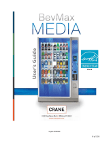
1. Decide whether to mount the Telemeter using
the three supplied self-tapping screws (Figure
5), or with a strip of Velcro attached to the
back of the Telemeter.
2. Select a location in the main cabinet or door
where the Telemeter is accessible for service
and protected from moisture. To prevent any
water intrusion, mount the Telemeter vertically
with the cables hanging down. Make sure it
will not interfere with any moving parts and
allow for cable routing.
3. If mounting with screws, screw the self-tapping
screws into the frame of the door or machine. If
using Velcro, attach a strip of Velcro to the frame of
the door or machine and stick the Telemeter to it.
4. Connect the Magnetic Base Antennas (#V8W-
UP0101290) MCX connectors into the ANTENNA
ports found on the bottom of the Telemeter.
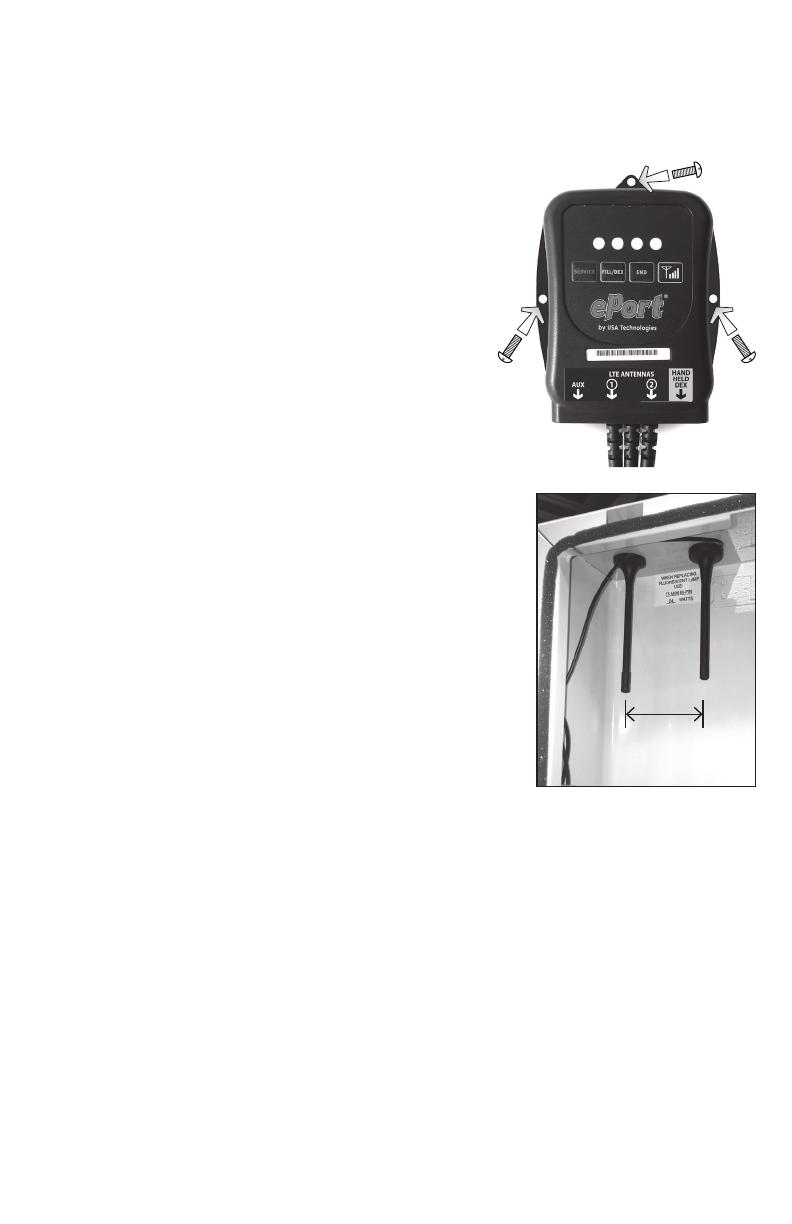
5. Place the antennas on top of, or inside the vending
machine on a metal surface no closer than 6 inches
apart. Make sure the antennas are not surrounded
by signal weakening metal support brackets or lo-
cated near the Telemeter or the control board when
the door is shut. This will improve connectivity to
the cellular tower. (Figure 6).
6. Tie the antenna cable to the nearest cable from the Telemeter.
7. Disconnect the MDB connectors in the vending machine between the machine
Control Board and the existing payment devices. Connect the MDB Cable from
the G10-S Telemeter to the MDB connectors going to the machine Control Board
and the existing payment devices. Ensure the connectors latch  rmly together.*
8. Plug the 6-pin black connector from the Telemeter cable into the cable from the
Card Reader. Ensure the connectors latch  rmly together.
9. Either connect the DEX cable with the standard jack plug from the Telemeter to
the vending machine DEX port (for remote DEX reporting), or leave the DEX cable
hanging loose if no remote DEX is to be used. Test all connections made.
FIGURE 5
* NOTE: When a Bill Recycler is present, the ePort must be plugged into the MDB bus
ahead of the Bill Recycler so that it can communicate properly with the VMC.
FIGURE 6
6” min
7
4. VERIFY THE INSTALLATION
1. Power up the vending machine and observe the LEDs of the G10-S Telemeter.
When the green LED blinks, the Telemeter has initialized.
2. Once the Telemeter has initialized the LTE Modem and connected to the wireless
network, the Card Readers display should read Swipe or Tap To Begin. “
3. At this point you can perform a test vend with a USA Technologies Pass Card or
credit card.
4. We recommend recording the ePort G10-S Telemeter serial number and vending
machine ID for accounting purposes.
5. Contact USAT Customer Care if you have any questions – 888-561-4748.
You must have a signed ePort Connect Services Contract and bank account as-
signed to this device for it to be able to accept credit card transactions. Please
call USA Technologies Customer Care at 888-561-4748, if you need activation
documents.
DEX Cable Card Reader
Cable
MDB Cable
FIGURE 7 G10-S TELEMETER CABLES
#VVXUD0101912 REV I
CANTALOUPE CUSTOMER CARE
Contact Cantaloupe Customer Care for technical support and to request
additional parts, information, and pre-authorization forms.
Phone: 888.561.4748
FAX: 610.989.9695
Online Store: https://store.cantaloupe.com/
https://www.seedlive.com https://www.cantaloupe.com
Malvern, PA 19355
This device complies with Part 15 of the FCC Rules. Operation is subject to the following two condi-
tions:
1. This device may not cause harmful interference
2. This device must accept any interference received, including interference that may cause
undesired operation.
All contents © Copyright 2017 USA Technologies, Inc.
All rights reserved.
Customer Website Login Company Site
This guide was created during the Company's tenure as USA Technologies, Inc.
The Company rebranded to Cantaloupe, Inc. April 19th, 2021. For contact information
please visit www.cantaloupe.com.
CANTALOUPE WEBSITE ADDRESSES
  • Page 1 1
  • Page 2 2
  • Page 3 3
  • Page 4 4
  • Page 5 5
  • Page 6 6
  • Page 7 7
  • Page 8 8

cantaloupe ePort G10-S User guide

Type
User guide

The cantaloupe ePort G10-S is an advanced card reader and telemeter system designed to enhance your vending machine's payment capabilities. With its ability to accept credit/debit card transactions through card swipe or RF technology, the G10-S provides your customers with a convenient and secure payment option. By connecting to your machine's MDB interface, the G10-S seamlessly integrates with your existing payment system. Installation is straightforward with the included mounting hardware and step-by-step instructions.

Ask a question and I''ll find the answer in the document

Finding information in a document is now easier with AI