Page is loading ...

EDFA300S and EDFA300P
C-Band Erbium-Doped
Fiber Amplifiers
Operating Manual

Erbium-Doped Fiber Amplifiers
Table of Contents
Warning Symbol Definitions ............................................................................................. 1
Safety................................................................................................................................... 2
Description ......................................................................................................................... 4
3.1. Shipping List ................................................................................................................. 4
Setup ................................................................................................................................... 5
4.1. Setting the AC Line Voltage ......................................................................................... 5
4.2. Changing the Fuse ....................................................................................................... 5
4.3. Initial Setup ................................................................................................................... 5
4.4. Making Fiber Connections to the Amplifier ................................................................ 5
Operation ............................................................................................................................ 7
5.1. Front and Back Panel Overview .................................................................................. 7
5.2. Turning On the Amplifier .............................................................................................. 7
5.3. Adjusting the Fiber Amplifier Gain .............................................................................. 8
5.4. Turning the Fiber Amplifier Off .................................................................................... 8
Remote Operation from Command-Line Interface ......................................................... 9
Making Safety Interlock Connections ........................................................................... 10
Troubleshooting ............................................................................................................... 11
General Maintenance ....................................................................................................... 12
9.1. Cleaning ...................................................................................................................... 12
9.2. Connector Cleaning .................................................................................................... 12
Specifications ................................................................................................................... 13
Mechanical Drawings ...................................................................................................... 15
Regulatory ........................................................................................................................ 17
12.1. Waste Treatment is Your Own Responsibility .......................................................... 17
12.2. Ecological Background .............................................................................................. 17
Declaration of Conformity .............................................................................................. 18
Thorlabs Worldwide Contacts ........................................................................................ 19

Erbium-Doped Fiber Amplifiers Chapter 1: Warning Symbol Definitions
Rev A, October 27, 2021 Page 1
Warning Symbol Definitions
Note: Throughout this manual, references to temperature are with respect to °C.
Below is a list of warning symbols you may encounter in this manual or on your device.
Symbol
Description
Direct Current
Alternating Current
Both Direct and Alternating Current
Earth Ground Terminal
Protective Conductor Terminal
Frame or Chassis Terminal
Equipotentiality
On (Supply)
Off (Supply)
In Position of a Bi-Stable Push Control
Out Position of a Bi-Stable Push Control
Caution: Risk of Electric Shock
Caution: Hot Surface
Caution: Risk of Danger
Warning: Visible or Invisible Laser Radiation
Caution: Spinning Blades May Cause Harm

Erbium-Doped Fiber Amplifiers Chapter 2: Safety
Page 2 TTN256521-D02
Safety
All statements regarding safety of operation and technical data in this instruction manual will only apply when the
unit is operated correctly.
SHOCK WARNING
High voltage inside. To avoid electrical shock, before powering the unit on, make sure that the
protective conductor of the 3-conductor power cord is correctly connected to the protective earth
contact of the socket outlet. Improper grounding can cause electric shock resulting in severe injury
or even death. Do not operate without cover installed.
EXPLOSION WARNING
This instrument must not be operated in an explosion endangered environment.
LASER WARNING
Avoid Exposure – Radiation Emitted from apertures. Do not look into the laser aperture while the
laser is on. Injury to the eye may result. Laser should not be turned on unless there is an optical
fiber connected to the laser output port. Caution – Use of controls or adjustments or performance of
procedures other than those specified herein may result in hazardous radiation exposure.
CAUTION
Note: This equipment has been tested and found to comply with the limits for a Class B digital
device, pursuant to part 15 of the FCC Rules. These limits are designed to provide reasonable
protection against harmful interference in a residential installation. This equipment generates, uses
and can radiate radio frequency energy and, if not installed and used in accordance with the
instructions, may cause harmful interference to radio communications. However, there is no
guarantee that interference will not occur in a particular installation. If this equipment does cause
harmful interference to radio or television reception, which can be determined by turning the
equipment off and on, the user is encouraged to try to correct the interference by one or more of the
following measures: Reorient or relocate the receiving antenna.—Increase the separation between
the equipment and receiver.—Connect the equipment into an outlet on a circuit different from that to
which the receiver is connected.—Consult the dealer or an experienced radio/TV technician for help.
CAUTION
This instrument should be kept clear of environments where liquid spills or condensing moisture
are likely. It is not water resistant. To avoid damage to the instrument, do not expose it to spray,
liquids, or solvents.

Erbium-Doped Fiber Amplifiers Chapter 2: Safety
Rev A, October 27, 2021 Page 3
The unit is supplied with a region-specific power cord. If using your own power cord, make sure it is IEC 320
compatible.
Make sure that the line voltage rating marked on the rear panel agrees with your local supply and that the
appropriate fuses are installed. Changing of the mains fuse can be done by the user (see Section 4.2, Changing
the Fuse). With the exception of the mains fuses, there are no user serviceable parts in this product.
Do not operate in wet or damp conditions. Do not obstruct the air ventilation slots in the housing!
This device can only be returned when packed into the complete original packaging, including all foam packing
inserts. If necessary, ask for a replacement package.
Mobile telephones, cellular phones, or other radio transmitters should not to be used within the range of three
meters of this unit since the electromagnetic field intensity may exceed the maximum allowed disturbance values
according to EN50082-1.

Erbium-Doped Fiber Amplifiers Chapter 3: Description
Page 4 TTN256521-D02
Description
Thorlabs’ EDFA300S and EDFA300P are core-pumped Erbium-doped fiber amplifiers that provide >40 dB small
signal gain and >300 mW saturated output power. The amplifiers are offered in a compact, turnkey benchtop
package with FC/APC input and output connectors and in two single-mode (SM) and polarization-maintaining (PM)
models. The EDFA300S SM (non-PM) amplifier is polarization-insensitive and input/output fibers to the amplifier
are standard single-mode fiber (SMF-28 Ultra). The EDFA300P PM amplifier is polarization sensitive, only
amplifying light that is linearly polarized along the slow axis. The input and output fibers of the PM amplifier are
polarization maintaining fiber (PM1550-XP) and the connector keys are aligned the slow axis of the fibers. The
EDFAs include precision current drivers to adjust the pump laser power in the amplifier. The current adjustment,
done through an adjustment knob on the front panel, varies the amplifier gain. The amplifier includes input and
output isolators to protect the input laser source from any amplified spontaneous emission or back reflections, as
well as to prevent the pump light from exiting the amplifier.
The EDFA gain can be controlled in constant current control (ACC) mode via the front panel interface. The pump
current of the amplifier is adjustable through the instrument's front panel, allowing the user to vary the gain and
output power. The display screen shows the pump level, as well as the temperature and emission status. An
indicator light is also included on the enable button to show when the internal laser is active. In addition to this mode
of operation, the EDFA can be operated in constant power control (APC) and constant gain control (AGC) modes
using a command-line interface via USB connection with a PC. These modes of operation allow the user to control
the amplifier for a fixed output power level or a fixed gain value. The amplifier automatically adjusts the pump current
in order to maintain the power or gain target values. For further information regarding all three modes of operation,
please see Chapter 5.
For added safety, there is an interlock connector located on the rear panel that must be shorted in order for the
output to be enabled. This can easily be configured to be triggered by doors to disable the fiber amplifier in unsafe
conditions. An enable button must be set to activate the amplifier, and a green LED indicator displays the current
state of the unit. There is a 3 second delay before the fiber amplifier turns on, and the user is warned by the rapidly
blinking LED.
The amplifier includes a universal power supply allowing operation over 100 to 240 VAC without the need for
selecting the line voltage. The fuse access is conveniently located on the rear panel.
3.1. Shipping List
The EDFA300 units consist of the following components:
• C-Band Erbium-Doped Fiber Amplifier in Benchtop Package
• Interlock-Shorting BNC Connector
• Region-Specific Power Cord
• FBC250 Connector and Bulkhead Cleaner
• 1 m long FC/APC patch cables (P3-SMF28Y-FC-1 or P3-SMF28E-FC-1 for SM, P3-1550PMY-1 or P3-
1550PM-FC-1 for PM); please see section 4.4 for how to safely connect to the amplifier ports and minimize
the risk of connector damage.
• Sacrificial fiber interface for connection to the output port (please see section 4.4).

Erbium-Doped Fiber Amplifiers Chapter 4: Setup
Rev A, October 27, 2021 Page 5
Setup
CAUTION
Prior to using the EDFA systems, it is highly recommended to clean the input and output bulkheads
as well as the connector facets to be connected to the bulkheads. Failure to clean the connectors
can result in damage to the internal connectors in the EDFA as well as the connectors on fiber
patch cables connected to the amplifier.
Please follow one of the two recommended methods to connect the output of the amplifier to the
optical setup. Failure to use one of these methods can significantly increase the risk of damaging
the output connector of the amplifier.
When cleaning the connectors, ensure that the EDFA is powered off by turning off the push-button
switch. Never inspect optical connectors unless all light sources in your setup have been switched
off. Please refer to Section 9.2 for further instructions regarding connector cleaning.
4.1. Setting the AC Line Voltage
The fiber amplifier has been shipped configured for 100 to 240 VAC operation. There is no end user adjustment of
the line voltage for 110 or 220 VAC. The user needs to select the correct AC cord for their location.
4.2. Changing the Fuse
To change the power fuse, follow the following steps.
1. Remove the AC power cord if it is connected to the unit.
2. Locate the fuse tray directly adjacent to the AC power cord connection on the rear panel of the unit.
3. Carefully use a flat blade screwdriver to open the fuse tray.
4. Remove the existing fuses and install two fuses with the appropriate specifications. The replacement fuses
must be 5 mm x 20 mm, 2 A, 250 VAC, slow-blow type.
5. Push the fuse tray back into place making sure that it snaps and sits correctly.
6. Connect the appropriate power cord into the AC receptacle and plug the unit in.
4.3. Initial Setup
1. Set the unit on a dry, level working surface.
2. Plug the female end of the provided AC line cord into the IEC input receptacle on the rear of the unit. Plug
the male end into a properly grounded AC socket.
3. Install the interlock BNC connector. (See Chapter 7 for details on the interlock circuitry.)
4.4. Making Fiber Connections to the Amplifier
1. Input Connection: Connect the input to be amplified to the input fiber receptacle using a FC/APC fiber
patch cable, carefully cleaning both the input FC bulkhead connector and the patch cable connector
beforehand.
2. Output Connection: It is highly recommended to minimize the number of times that a cable is connected
to the output receptacle in order to reduce the probability of damage to this connector. Repeated connection
to this port can cause a build-up of contamination on the internal connector surface, which can damage the
connector at high powers. There are two components shipped with every amplifier for this purpose:
a. A one meter FC/APC patch cable is included. The connectors on this cable have been pre-cleaned
and are ready to mate with the output of the amplifier. Please inspect one end of this cable for any

Erbium-Doped Fiber Amplifiers Chapter 4: Setup
Page 6 TTN256521-D02
contamination, and connect one end of the cable to the amplifier. Keep this end connected at all
times, while using the other end to make connections to the optical setup. This end should still be
regularly inspected and cleaned when needed. This approach protects the output receptacle on
the amplifier from repeated connections and the resulting optical damage. In the event that the
cable end is damaged due to over-usage, it can be replaced with a new cable or a new fiber pigtail
can be spliced.
b. A sacrificial optical interface compatible with FC/APC connectors is supplied with the amplifier. This
interface can be plugged into the output port of the amplifier. All fiber cable connections can be
made to this interface while the interface should stay connected to the output port. This option will
introduce approximately 0.7 dB of extra insertion loss, but it offers the advantage of preventing
direct contact between a fiber cable and the internal connector surface to reduce the risk of damage
to the internal connector. Additionally, using this method shortens the fiber path outside the
amplifier for applications that are sensitive to the fiber length.
Important Note: Please note that when the amplifier is enabled, it generates amplified spontaneous
emission (ASE) even when there is no input light entering the amplifier. This should be considered
when connecting measurement instruments to the output port of the amplifier and when inspecting the
fiber connectors.

Erbium-Doped Fiber Amplifiers Chapter 5: Operation
Rev A, October 27, 2021 Page 7
Operation
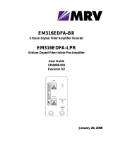
5.1. Front and Back Panel Overview
Figure 1 Front and Rear Panels of the Fiber Amplifier (EDFA300S or EDFA300P)
5.2. Turning On the Amplifier
1. Please consult with your organization’s laser safety officer regarding proper operation of the amplifier at
your institution.
Amplifier Input Port
FC/APC Bulkhead
Pump Current Adjustment Knob
Push to adjust.
Power Key Switch
Display
Indicates pump current level (0-100%),
temperature status, and emission status.
Remote Interlock Input (BNC)
See page 10 for connection logic.
USB Diagnostic Port
For factory use only.
Fuse Tray
See Section 4.2 for
replacement details.
Amplifier Output Port
FC/APC Bulkhead
AC Power Cord
Connector
Cooling Fan - Do Not Block
Moves air from vent holes on the bottom and sides.
Periodically remove dust buildup from vents for
best operation.
AC Power On/Off
Switch
Enable Switch
and Emission
Indicator

Erbium-Doped Fiber Amplifiers Chapter 5: Operation
Page 8 TTN256521-D02
LASER WARNING
The amplifier generates invisible amplified spontaneous emission (ASE) even without any optical
input. The power level of the ASE can be as high as 200 mW. Therefore, all laser safety measures
should be followed even if the input light to the amplifier has been disconnected or switched off.
Additionally, it should be noted that connecting a laser to the output port of the amplifier by mistake
can cause damage to the laser due to the ASE light getting coupled into the laser source.
2. Turn on the AC power switch on the back panel.
3. Turn on the POWER key switch. The display will turn on. The pump current set-point (in % of max) will be
displayed in the middle of the screen.
4. Check the temperature status on the bottom left corner of the display. It should show “OK”. If the
temperature status shows “Stabilization” for more than 30 seconds or if it shows “Error”, please turn the
unit off and contact technical support.
5. Check the emission status of the device on the bottom right corner of the screen. It should show “Off” prior
to enabling the amplifier.
6. Make sure the interlock input on the back panel is short-circuited. See Chapter 7 for detailed instructions.
7. Press and release the ENABLE switch to activate the fiber amplifier. There will be a 3 second delay before
the fiber amplifier powers up. During this time, the ENABLE indicator will light up and blink.
8. Adjust the pump current set-point to the desired value by pressing the adjustment knob once. The “%” sign
blinks in the adjustment mode and it times out after 5 seconds. The knob must be pressed again after the
time-out in order to make additional adjustments to the pump current set-point.
9. Ensure that the temperature status still shows “OK” after the pump current has been increased to the
desired level. The amplifier is now producing gain and is ready to use.
5.3. Adjusting the Fiber Amplifier Gain
The fiber amplifier gain and output power are controlled by varying the pump current set-point. The system
specifications represent the performance at max operating set-point (100%). Each unit is shipped with a test data
sheet that shows the amplifier output power at two different input power levels (0 dBm and -20 dBm) as a function
of the pump current set-point. The data can be used as a reference to adjust the pump current set-point for a desired
gain level.
5.4. Turning the Fiber Amplifier Off
• Disabling the amplifier emission - The amplifier output can be turned off by pressing and releasing the
ENABLE switch. The pump diode temperature will be maintained even when the amplifier is disabled. The
temperature status should show “OK” after the amplifier has been disabled.
• Power Down - When completely powering down an enabled unit, first press and release the ENABLE
switch and then turn off the POWER key switch, which will turn OFF the entire unit. Anytime the unit is
turned OFF and then turned back ON, the fiber amplifier will be disabled until the ENABLE switch is pressed.
If the amplifier is not being used for an extended period of time, it is recommended to turn off the AC power
using the switch located on the back panel of the instrument. Please note that the pump current set-point
goes back to 0% after each AC power cycle.

Erbium-Doped Fiber Amplifiers Chapter 6: Remote Operation from Command-Line Interface
Rev A, October 27, 2021 Page 9
Remote Operation from Command-Line Interface
The Command Line Interface (CLI) provides the user with a method of controlling the EDFA remotely over the
USB interface that is emulating a serial port. A standard terminal program (such as Tera Term) can be used to
send commands to the EDFA and receive responses. The following functions are available through the CLI:
• Enabling and disabling the amplifier emission.
• Reading status indicators
• Setting the current set-point value in the ACC operation mode.
• Operating the system in APC or AGC modes at user-defined power or gain values.
The list below shows the list of available commands along with a brief description and syntax:
Command: Command description:
Help DISPLAY COMMANDS – Lists commands available to the user
le ENABLE LASER – Turns the Pump LASER ON
ld DISABLE LASER - Turns the Pump LASER OFF
sloc SET LASER DIODE OPERATING CURRENT – Sets the Pump LASER output
sloc <current>
Set current is between: 0 to 100 percent
gloc GET LASER DIODE OPERATING CURRENT – Returns the Pump LASER
output
stat STATUS REGISTER – Returns the following status info:
Interlock : Open or Closed
Temp stable: Stable or Unstable
Temp fault : No Fault or Fault
LASER : ON or OFF
runpwr RUN PID POWER CONTROL – Enables the amplifier and starts the PID power
control loop to keep output power constant
runpwr <power>
<power> can be any positive value representing the output power in
micro-Watts
rungain RUN PID GAIN CONTROL – Enables the amplifier and starts the PID gain
control loop to keep the amplifier gain constant
rungain <gain>
<gain> can be any positive value representing the gain value in linear
scale.
Please note that the system default mode is the ACC mode. This mode is accessible by the front panel operation
and the current set point is adjustable using the front panel knob as well as the CLI. The instrument enters this
mode after every power cycle. Enabling the laser from the front panel switch or by executing the “le” command
results in entering the ACC mode of operation. The APC and AGC modes of operation can be activated using the
commands “runpwr” and “rungain”. These commands enable the amplifier and start control loops to maintain a
constant level of output power or gain. The control loops can be interrupted by turning the laser off using the
command “ld”. Alternatively, by setting the power or gain to zero, the control loop is interrupted and amplifier
emission is turned off. If the control loop fails to reach its target under either APC or AGC modes, the closed-loop
operation is automatically terminated and the amplifier id disabled. Upon exiting the control loop, the amplifier goes
back to the default ACC mode.

Erbium-Doped Fiber Amplifiers Chapter 7: Making Safety Interlock Connections
Page 10 TTN256521-D02
Making Safety Interlock Connections
The EDFA300S and EDFA300P instruments are equipped with a remote interlock connector located on the rear
panel. In order to enable the fiber amplifier, a short circuit must be applied across the terminals of the Remote
Interlock connector. This connection is made available to allow the user to connect a remotely actuated switch to
the connector (i.e. an open door indicator).
The switch that is connected to this interlock must be normally open (N.O.), meaning that it has to be closed in
order for the unit to be enabled. If the switch is changed to an open state, the amplifier will automatically shut down.
If the switch returns to a closed condition, the amplifier will not re-enable until the ENABLE switch is pressed.
All units shipped from Thorlabs are configured with a shorting BNC device installed in the interlock connector. If you
are not going to use this feature then you can leave the shorting device installed and the unit will operate normally,
as described throughout this manual. If you wish to make use of the interlock feature you will need to acquire the
appropriate mating connector (BNC male) and wire it to your remote interlock switch.

Erbium-Doped Fiber Amplifiers Chapter 8: Troubleshooting
Rev A, October 27, 2021 Page 11
Troubleshooting
CAUTION
Invisible Laser Radiation. Do not look directly into the fiber receptacle. Use a viewing card to help
determine whether the fiber amplifier is generating an output.
WARNING
Never open the amplifier housing cover for troubleshooting. Refer servicing to qualified personnel.
The following table describes some typical problems that may be encountered while using the EDFA and possible
solutions to these problems.
Problem
Solution
Unit does not turn on when switching the
power ON/OFF on the front panel.
1. Make sure the AC line cord is fully inserted into the
AC Input receptacle and plugged into an outlet
providing 100 to 240 VAC. Also ensure that the AC
power switch on the back panel has been turned on.
2. Fuse(s) may be open. Refer to Section 4.2 for
information on replacing open fuses. If the problem
persists, please return the unit to Thorlabs for
evaluation.
Unit powers on but does not enable when
pressing the ENABLE button.
1. Check to make sure the interlock connector is
installed on the rear panel. See Chapter 7 for details.
2. Check the temperature status on the front panel
display. If temperature status is not OK for more than
30 seconds, turn the unit off and contact technical
support.
Unit is enabled but there is no output.
1. Check to make sure you are using the correct type
of fiber patch cable for the particular wavelength and
FC/APC connector type.
2. Check to make sure the input connector to the
EDFA has power.
3. Inspect the connectors on both cables connected to
input and output ports to ensure they are clean and not
damaged.

Erbium-Doped Fiber Amplifiers Chapter 9: General Maintenance
Page 12 TTN256521-D02
General Maintenance
Aside from the AC input fuse, there are no user serviceable parts in this product. If you suspect something has
failed in the unit, please contact Thorlabs for advice on returning the unit for evaluation.
Always clean fiber optic connectors that will be inserted into the system and install the dust cap whenever the source
is not being used. Allowing dust and dirt onto the fiber end faces will degrade coupling efficiency and possibly
damage the fiber patch cables, both inside and outside.
9.1. Cleaning
The housing can be cleaned using a soft, slightly damp cloth. Avoid using any solvents on or near the unit. Keep
the vent holes on the sides, rear and bottom of the enclosure free of dust buildup. Restricted airflow will cause the
temperature controls to operate inefficiently and, in extreme cases, loss of temperature control.
9.2. Connector Cleaning
Always clean the ferrule end of your fiber patch cables as well as the input and output FC bulkheads prior to inserting
the fiber patch cables into the FC bulkheads. Thorlabs offers the FCC-7020 Fiber Cleaning Cloth Spool, which can
be used for cleaning the ferrule ends of the patch cables.
Additionally, each unit is shipped with an FBC250 Bulkhead and Connector Cleaner for cleaning the input and
output bulkheads.
Figure 2 FBC250 Bulkhead and Connector Cleaner
To use the FBC250 Bulkhead and Connector Cleaner, please refer to the instructions shipped with the FBC250.

Erbium-Doped Fiber Amplifiers Chapter 10: Specifications
Rev A, October 27, 2021 Page 13
Specifications
Item #
EDFA300S
EDFA300P
Amplifier Specifications (Taken at 100% Pump Current Set-Point)
Operating Wavelength Rangea
1530 nm - 1565 nm
Saturated Output Power b,c
>24.5 dBm
Small Signal Gain (@ -20 dBm Input
Power)b
>40 dB
Noise Figure (@ 3 dBm Input Power)b
<6 dB
Output Power Stabilityd (Constant Current
Model @ 3 dBm Input Power)
<±2% Over 24 Hours
Output Power Stabilityd (Constant Power
Model @ 3 dBm Input Power)
<±0.5% Over 24 Hours
Total Dispersion Within Amplifiere
<0.14 ps/nm
Laser Class
3B
Fiber Specifications
Output Polarization
Random
Linear, Aligned to Slow Axis
Polarization Extinction Ratio
N/A
>25 dB
Polarization-Dependent Gain
<0.5 dB
N/A
Return Loss at Input Port
>50 dB
Input / Output Isolation
>30 dB
Input / Output Fiber Type
SMF-28-J9
PM1550-XP
Input / Output Fiber Connectors
FC/APC Compatible, 2.0 mm Narrow Key
a. The wavelength range over which the small signal gain (at -20 dBm input power) does not fall below
35 dB.
b. Specified at 1550 nm. Please refer to published data on the Thorlabs website for typical curves showing
the variation of each parameter with wavelength.
c. Please refer to published data on the Thorlabs website for the scaling of the output power vs. the input
power.
d. After a 15 minute warm-up time, for ambient temperature fluctuations ±2 °C.
e. Amplifier dispersion can be minimized using a dispersion-compensating fiber patch cable. Patch cables
with custom dispersion compensation are possible by contacting Tech Support.
Absolute Maximum Ratings
Absolute Maximum Input Power
13 dBm
Absolute Maximum Output Power
26 dBm
Operating Temperature
15 to 30 °C
Storage Temperature
-10 to 40 °C

Erbium-Doped Fiber Amplifiers Chapter 10: Specifications
Page 14 TTN256521-D02
General Specifications
Input Voltage
100 - 240 VAC, 50 - 60 Hz
Input Power
20 W (Max)
Fuse Rating
2 A, 250 V
Fuse Type
Time-Lag (Slow-Blow)
Fuse Size
5 mm x 20 mm
Dimensions (W x D x H)
250.0 mm x 300.0 mm x 122.2 mm
(9.84" x 11.81" x 4.81")
Weight
7.5 lbs

Erbium-Doped Fiber Amplifiers Chapter 11: Mechanical Drawings
Rev A, October 27, 2021 Page 15
Mechanical Drawings
Figure 3 EDFA300S Mechanical Drawing

Erbium-Doped Fiber Amplifiers Chapter 11: Mechanical Drawings
Page 16 TTN256521-D02
Figure 4 EDFA300P Mechanical Drawing

Erbium-Doped Fiber Amplifiers Chapter 12: Regulatory
Rev A, October 27, 2021 Page 17
Regulatory
As required by the WEEE (Waste Electrical and Electronic Equipment Directive) of the European Community and
the corresponding national laws, Thorlabs offers all end users in the EC the possibility to return “end of life” units
without incurring disposal charges.
This offer is valid for Thorlabs electrical and electronic equipment:
• Sold after August 13, 2005
• Marked correspondingly with the crossed out “wheelie bin” logo (see right)
• Sold to a company or institute within the EC
• Currently owned by a company or institute within the EC
• Still complete, not disassembled and not contaminated
As the WEEE directive applies to self-contained operational electrical and electronic products, this end of life take
back service does not refer to other Thorlabs products, such as:
• Pure OEM products, that means assemblies to be built into a unit by the user (e. g. OEM laser driver cards)
• Components
• Mechanics and optics
• Left over parts of units disassembled by the user (PCB’s, housings etc.).
If you wish to return a Thorlabs unit for waste recovery, please contact Thorlabs or your nearest dealer for further
information.
12.1. Waste Treatment is Your Own Responsibility
If you do not return an “end of life” unit to Thorlabs, you must hand it to a company specialized in waste recovery.
Do not dispose of the unit in a litter bin or at a public waste disposal site.
12.2. Ecological Background
It is well known that WEEE pollutes the environment by releasing toxic products during decomposition. The aim of
the European RoHS directive is to reduce the content of toxic substances in electronic products in the future.
The intent of the WEEE directive is to enforce the recycling of WEEE. A controlled recycling of end of life products
will thereby avoid negative impacts on the environment.
Wheelie Bin Logo

Erbium-Doped Fiber Amplifiers Chapter 13: Declaration of Conformity
Page 18 TTN256521-D02
Declaration of Conformity
/