polishedpro | 5.0mm Rigid Core
Product Guide

polishedpro | 5.0mm Rigid Core
DuraDecor | P: (855) 700 - 5666 | customercare@duradecor.com | duradecor.com | revised on 06.27.22 | Page 2
General Information
Limitations
The optimal operating temperature for use is between
40°F to 90°F (4°C to 32°C). Avoid prolonged exposure to
direct sunlight or other heat sources where temperatures
will exceed 90°F (32°C), as discoloration or damage may
occur. This product is not suitable for heavy rolling loads
or heavy commercial areas. Do not install in areas that may
be subjected to sharp, pointed objects, such as stiletto
heels, cleats or spikes. Do not allow product to be directly
exposed to extreme heat sources, such as self-cleaning
ovens or other high-heat equipment. Do not install outdoors
or in areas that may be exposed to repeated and sustained
UV/IR rays, as product may fade, discolor or experience
excessive movement. Refer to the Material Usage Guide
and, if applicable, the Wet Areas technical bulletin for a full
list of acceptable areas and information about approved
areas of use. Do not use rubber tires, casters or rubber-
backed walk-o mats directly on the ooring surface, as
permanent staining may occur. Do not install nails, screws,
bolts, moldings, accessories or heavy xed furniture, such
as cabinets, counter tops, islands or commercial equipment,
directly on, into or through the ooring material, as this
may restrict the natural movement of the oor and cause
gapping/buckling.
Copies of ASTM documents are available for purchase at
www.astm.org.
Receiving Material & Storage
Remove all plastic and strapping from the product after
delivery. Conrm that the ooring product color, style and
quantity are correct, and check lot numbers, in the event
you’ve received more than one. Carefully check all materials
for shipping damage and note all damage on the bill of
lading before accepting the delivery. Material accepted with
visible shipping damage that is not reported on the bill of
lading is not covered under warranty. The oor covering
and accessories must be stored in dry indoors conditions
between 40°F to 90°F (4°C to 32°C). Do not store outside
(even in containers) and do not stack pallets.
Warning
All local, state, and federal regulations must be followed;
this includes the removal of in-place asbestos ooring and
adhesive, as well as any lead-containing materials. The
Occupational Safety and Health Administration (OSHA)
has exposure limits for people exposed to respirable
crystalline silica; this requirement must be followed. Do
not use solvent or citrus-based adhesive removers. When
appropriate, follow the Resilient Floor Covering Institute’s
(RFCI) Recommended Work Practice for Removal of Existing
Floor Covering and Adhesive. Always wear safety glasses
and use respiratory protection or other safeguards to avoid
inhaling any dust. The label, installation, and maintenance
instructions along with the technical data sheet, limited
warranty and any appropriate Safety Data Sheet (SDS)
of all products must be read, understood, and followed
prior to installation. Do not leave spills unattended - wipe
up promptly, and allow the oor covering to dry before
tracking.
Documentation
Record and/or photograph the site conditions, test results,
and any corrective measures taken. All relevant pre-
installation documentation, as well original product invoices
and associated shop drawings or project information,
should be stored for the entire warranty period.
Site Conditions & Storage
The prepared installation area must be fully enclosed and
weather-tight. During the installation, any direct sunlight
should be blocked using window treatments or other
protection. The ambient temperature during installation
must be >60°F (16°C), with a recommended maximum of
80°F (27°C). The ooring does not require an acclimation
period.
Note: When installing at temperatures >80°F (27°C), the
width of the expansion gap may increase as the ooring
temperature decreases.

polishedpro | 5.0mm Rigid Core
DuraDecor | P: (855) 700 - 5666 | customercare@duradecor.com | duradecor.com | revised on 06.27.22 | Page 3
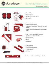
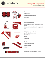
Recommended Tool List
• Knee Pads
• Safety Glasses
• Cut-Resistant Safety Gloves
• Dust Mask
• HEPA-Filtered Vacuum
• Oscillating Multi-Tool or Hand Saw (for door
jambs)
• Jigsaw with Carbide Blades(for complicated
cuts)
• 2 lb. (~32 oz.) Dead Blow Hammer
(preferred) or Rubber Mallet
• Speed Square
• Pencil
• Chalk Line
• Tape Measure
• Utility Knife with Blades
• Wedge Spacers
• Pull Bar
• 6-foot and 1-foot Straight Edge or Level

polishedpro | 5.0mm Rigid Core
DuraDecor | P: (855) 700 - 5666 | customercare@duradecor.com | duradecor.com | revised on 06.27.22 | Page 4
1. Substrate Preparation
General Substrate Guidelines
Ensure the substrate is clean, dry, at, sound and
suitably prepared according to these instructions prior to
installation, as manufacturer is not responsible for problems
related to substrates that have not been properly prepared.
All substrates must be free of visible water or moisture,
dust, residual adhesives and adhesive removers, solvents,
wax, oil, grease, asphalt, visible alkaline salts or excessive
eorescence, mold, mildew and all other extraneous
coating, lm, material or foreign matter. Substrate and/or
suboor deection, movement, or instability may cause
issues with the ooring installation – these are not covered
under warranty.
Flatness Guidelines
Check all substrates for atness prior to installation. All
substrates must have a oor atness of FF32 and/or have a
maximum deviation of < 1/8-in. gap (2 x US quarters should
not slide underneath) within 6-ft. and ≤ 1/16-in. gap (1 x US
quarter should not slide underneath) within 1-ft.. Substrates
that do not meet this requirement must be corrected
appropriately before installation begins.
Concrete Substrates
All concrete substrates must be at least 28-days old, free
of contaminates and structurally sound. If required, atten
and/or smooth the surface using a suitable, moisture-
resistant, commercial-grade leveling or patching compound,
following the product instructions. Do not install if water
or hydrostatic pressure is visible, present or suspected. If
a chemical adhesive remover has been used, contact the
technical department. For all on and below grade concrete
substrates refer to "Concrete Moisture Requirements".
All expansion joints must have a suitable expansion joint
covering system installed to allow for expansion and
contraction of the concrete. All dormant construction joints
and surface cracks > 1/4-in. must be cleared of all dust, dirt
and debris and lled with a rigid crack treatment designed
for use in construction joints or cracks. Follow the products
instructions and ensure surface is troweled ush with
surface of concrete.
Concrete Moisture Requirements
For all On and/or Below Grade concrete substrates, test
the surface to conrm it is absorbent (porous). Follow the
ASTM F3191 Standard Practice for Field Determination of
Substrate Water Absorption (Porosity) for Substrates to
Receive Resilient Flooring - water droplet(s) placed on the
surface must be absorbed into the concrete within 12-hours
for the surface to be considered absorbent. If required, the
concrete can be made porous by mechanical methods, such
as diamond grinding, a DiamaBrush buer attachment,
shotblasting or similar.
Installation Instructions
If the substrate cannot be made porous and will not have
a topical moisture mitigation system installed, install a ≥
6-mil thick polyethylene (PE) sheet, which is available at
most home improvement stores. Use sheeting that is ≤ 10-
ft. wide to prevent wrinkles and folds. Sheeting must be
installed over the entire area and extend at least 2-in. up the
walls. All seams must be overlapped and sealed according
to the product instructions.
Gypsum / Lightweight Concrete Substrates
Lightweight or gypsum substrates must be dry (according
to the product manufacturer’s requirements) and have a
minimum compressive strength of 2000 PSI when installed
over a wood substrate or 3000 PSI when installed over a
concrete substrate. Lightweight or gypsum substrates
must be installed and prepared in accordance with ASTM
F2419 or ASTM F2471, respectively. Gypsum and lightweight
substrates must be rmly bonded to a structurally sound
suboor. All cracked or fractured areas must be removed and
repaired with a compatible repair product. New or existing
gypsum or lightweight substrates may require a sealant
or primer be installed prior to resilient ooring installation
- follow the product manufacturer’s recommendations
regarding preparation for resilient ooring.
Wood Substrates
All wood substrates must be structurally sound, dry
and within the moisture content percent (MC%) for your
region. Wood substrates and suboors must be compliant
with and, if necessary, prepared in accordance with
ASTM F1482. Wood substrates should be of double layer
construction with a recommended total thickness of 1-in. or
more, depending on federal, state and local building codes.
Sleepers and sleeper systems must not make direct contact
with concrete.
Resinous Coating Substrates
When installing directly over a resinous coating, such as
an epoxy coating or a moisture mitigation system, ensure
the coating is clean and free of contaminates, structurally
sound, smooth, dry and has cured for the prescribed length
of time.
Metal Substrates
Metal substrates must be clean, dry, structurally sound
smooth and free of oil, rust and/or oxidation. When installing
in areas that may be subject to topical water, moisture
and/or high humidity, an anti-corrosive coating should be
applied to protect the metal substrate. Contact a local paint
or coating supplier for coating recommendations.
Other Substrates
Installing over existing resilient vinyl ooring is not
recommended. However, it may be possible over some
materials, such as VCT, VAT, quartz tile, solid vinyl tile, sheet
vinyl or linoleum, as well as existing hard surface ooring

polishedpro | 5.0mm Rigid Core
DuraDecor | P: (855) 700 - 5666 | customercare@duradecor.com | duradecor.com | revised on 06.27.22 | Page 5
substrates, such as terrazzo, porcelain or ceramic tile.
Ensure existing ooring is a single layer and is clean, dry,
sound, solid and well adhered. All loose material must be
removed and repaired or replaced. All grout lines and wide
seams greater than 1/4-in. in width and/or depth, as well
as any signicant substrate imperfections, must be lled
and troweled ush with a suitable cementitious patch. By
electing to install over any existing oor covering releases
the manufacturer from any responsibility regarding the
suitability and continued performance of that product,
including any resulting eect on the new oor covering.
Radiant Heating Requirements
When installing ooring over a substrate that contains a
radiant heating system, ensure that none of the heating
elements make direct contact with the ooring material.
Ensure radiant heat is no higher than 70° F (21° C) 8-hours
prior to and during the entire installation. After installation,
the radiant heat may be gradually increased over the course
of 24 hours, until normal operating temperature is reached.
Ensure the temperature of the radiant heating system does
not exceed 85° F (29.5° C) and avoid making abrupt changes
in radiant heating temperature.
Sound Control Substrates
Additional Sound Control Underlayments cannot be
used under this ooring. Any and all issues related to the
installation of additional, unapproved underlayments will
not be covered under warranty.
Unsuitable Substrates
These include, but are not limited to: any oating or loose
oor coverings, hardwood, carpet, cushioned vinyl, rubber,
cork, foam, asphalt tile, additional acoustical underlayments
and any substrate with visible mold, mildew, or fungi and
any substrate in wet areas, such as inside showers and
saunas. Do not install directly over any adhesive or adhesive
residue of any kind. Do not install in recreation vehicles,
campers or boats.
Note: Existing hardwood oor coverings will swell when
exposed to moisture - vinyl oor covering may restrict the
movement of moisture in hardwood, which may result in
ooring failure, especially when installed on or below grade.
Some hardwood oor coverings may also discolor vinyl
oor covering. Issues related to unsuitable substrate are
not covered under warranty.
Wet Area Guidelines
Some suboors and substrates, such as plywood, may be
sensitive to and damaged or deformed by topical liquids,
such as water, pet urine and spills. While polishedpro Rigid
Core Flooring is a waterproof product, water-sensitive
suboors may require additional protection to prevent
water exposure. When installing oor covering in wet areas,
ensure that bathmats or similar are used where appropriate
to decrease the amount of water that can collect on the
surface. Any and all spills should be cleaned up immediately
Installation Instructions
after discovering them and within 8 hours. Suboor
atness is critical to preventing water migration through
seams that may ex or peak due to foot trac and suboor
deection - be sure to check atness and make all necessary
adjustments prior to installing.
Water-sensitive substrate must have a ≥ 6-mil thick
polyethylene (PE) sheet (available at Hardware stores)
installed over the entire area and extend at least 2-in. up the
walls. All seams must be overlapped and taped according
to the product instructions. In addition, the area must be
separated from all other rooms using a suitable water-
resistant t-molding. Following ooring installation, the
plastic sheet must be trimmed ush with the surface of
the suboor. Prior to installing wall-base or molding, the
required perimeter expansion gap must be lled with a 100%
silicone caulk, including the wet area side of all t-moldings.
Additionally, all door jambs, plumbing and vertical surfaces
that won’t have wall-base or molding installed must be
sealed with 100% silicone caulk. Once the entire perimeter
has been lled or sealed, water-resistant wall-base, moldings
or other accessories may be installed. Apply a bead of
silicone caulk to the parts of the wall-base or moldings that
will make contact with the surface of the ooring. Ensure all
wall base and moldings are attached to the suboor, wall
or wall-base without compression, to allow movement and
cleanup any remaining silicone immediately. Do not anchor
wall-base or moldings into or through the oor covering.
2. Flooring Expansion
Expansion Gap
Expansion gaps are required around the entire perimeter
of the ooring and between the ooring and all adjacent
vertical surfaces, such as adjacent ooring, xed furniture,
thresholds, xtures, door jambs, and other protrusions -
this allows the ooring area to freely expand and contract
naturally. Do not adhere or anchor any accessories directly
to or through the ooring material, as this could restrict
natural movement resulting in an installation failure. The
required expansion gap depends on the installation area,
per the following:
• Areas that are ≤ 50 feet in length and/or width must
have a ≥ 1/4-in. expansion gap.
• Areas that are 50-85 feet in length and/or width must
have a ≥1/2-in. expansion gap.
• Three season rooms, sunrooms and other areas that
will not have continuous HVAC control must have a ≥
1/2-in. expansion gap.
• Hotel rooms that may undergo high-heat pest control
must have ≥ 1/2-in. expansion gap.
• Areas with very heavy furniture ≥ 800-lb. (363-kg)
must be isolated with a compatible t-molding and have
≥ 1/2-in. expansion gap.

polishedpro | 5.0mm Rigid Core
DuraDecor | P: (855) 700 - 5666 | customercare@duradecor.com | duradecor.com | revised on 06.27.22 | Page 6
Expansion Joint
When the total ooring length or width exceeds 85 feet,
a compatible t-molding must be installed to create an
expansion joint. Expansion joints must be wide enough to
accommodate an appropriate accessory and allow for the
appropriate expansion gap on either side. Accessories must
cover the ooring material by at least 1/8-in. on each side
and must be glued or anchored directly to the substrate.
Three season rooms, sunrooms and other areas that will
not have continuous HVAC control must be ≤30 feet in
length and/or width and must be isolated from other areas
with a compatible t-molding, to ensure that ooring does
not run room to room.
3. Flooring Installation
Installation Preparation
All wall-base should be removed before ooring installation.
Alternately, a quarter round molding (xed to the wall or
wall-base only) may be used. Undercut all wooden door
jambs and the rst -in. of any remaining wall-base (later
covered with molding) with an Oscillating Multi-Tool - the
height must be the thickness of the oor covering plus
1/64-in., which will allow the oor covering to expand and
contract naturally. Steel door jambs should be pattern-
scribed, leaving the required expansion gap. Use a color-
coordinated 100% silicone to ll the void. Clean the entire
area to be installed using a HEPA-ltered vacuum.
Inspect all material prior to and during installation to verify
that there are no visible defects, damages and excessive
shading, sheen or texture variations. Blend materials from
several cartons within the same lot to ensure a consistent
appearance. Some ooring products, colors and textures
have latent and acceptable color and shade variations. If
there are concerns regarding defects, shade, sheen or
texture variation, do not install material and consult a sales
representative or manufacturer’s technical sta. Labor
costs associated with materials installed with obvious
visual defects will not be covered under warranty.
Although mixing dierent lots within the same area
will not aect the performance of the product, it is not
recommended, as shade, sheen and texture variations may
be visible. Prior to installing, compare dierent lots side-by-
side from all directions and lighting conditions to conrm
acceptability for the owner or end-user. Material installed
with obvious visual dierences related to production lots
will not be covered under warranty.
Layout
Prior to installation, conrm the installation pattern and
direction per the design specications or work order. Planks
should be installed in a random pattern - plank end joints
should be randomly spaced by ≥ 8-in. Avoid "H" joints and
do not install in a "Stair-Stepped" installation pattern, while
ensuring no obvious pattern repeats emerge. Failure to
randomize the end joints could weaken the integrity of the
locking mechanism, which may lead to failure. Tiles must be
installed in a brick-bond or 1/3rd o-set pattern.
Starting Line
Determine the best wall to start the installation along –
typically, this is the longest straight wall with a doorway.
Measure the width of both ends of the room and, accounting
for the necessary expansion gaps, calculate the width of
your last row. If it is less than half the width of the oor
covering or if a balanced design is required, reduce the
width of the rst row accordingly. Use a chalk-line to mark
the outside edge of the rst row on the substrate.
If needed, trim the rst row by removing the side without
the extended locking mechanism (tongue) to t, accounting
for the expansion gap. To trim the rst row, either measure
and mark your cutlines or use the mirror-scribe method. To
mirror-scribe, place your selected piece on the opposite side
of the chalk-line, so that the chalk-line is above the extended
locking mechanism (tongue). Then, place a full piece ush
with the wall, overlapping your selected piece. Using the
overlapped piece as your guide, mark a cutline on your
selected piece with a pencil. Once marked, proceed with
trimming the rst row as detailed below.
Cutting
To cut the oor covering, carefully score along the cut line
at least twice with a sharp utility knife. When cutting across
the width of a piece, use a speed square as a guide. Snap
the piece downwards and, if necessary, trim the attached
underlayment from underneath. For complicated cuts, such
as around xtures or door jambs, use a jigsaw with a carbide
blade, following the tool’s safety instructions.
First Row (Slide)
At the left corner of the starting wall, position the rst
piece so that either the pre-cut side or the side without the
extended locking mechanism (tongue) is ush with the wall.
Place wedge spacers between the oor covering and the wall
to maintain the required expansion gap. Before connecting
the second pre-cut piece, lay it at on the substrate, adjacent
to the rst row and lined up with the end of the previous
piece. Then, while keeping the joint aligned, slide the ends
together, locking the joint into place.
Complete the entire rst row using this method. When you
reach a doorway, make sure the cut edge will be covered
by the door jamb and frame while maintaining the required
expansion gap.
Keeping the installation straight is critical - check the rst
row using a chalk line or similar and adjust or reinforce
the entire row with wedge spacers as needed to prevent
movement. The acceptable straightness tolerance is within
1/16-in. for > 20-ft. lengths or 1/32 -in. for < 20-ft. lengths.
Begin the following rows with a cut piece, perhaps from a
previous row, and follow the "Side Joints" detail below.
Side Joints (Angle)
Starting at the left corner, typically with a cut piece, insert
Installation Instructions

polishedpro | 5.0mm Rigid Core
DuraDecor | P: (855) 700 - 5666 | customercare@duradecor.com | duradecor.com | revised on 06.27.22 | Page 7
the side without an extended locking mechanism (tongue)
into the previous row at a ~25° angle. Make sure it is
properly seated and slides freely, then slide the piece into
position. The end joint must either be ush with the wedge
spacer (rst piece) or be closely aligned with the end of the
previous piece. Lay the piece at and complete the end joint
as detailed below.
End-Joints (Drop-Lock or Fold-Down)
Before locking end joints into place, check the alignment
at the joint and adjust as necessary. To engage the locking
mechanism, lightly tap along the raised piece using a 1-lb. (~
16-oz.) soft faced dead blow hammer (preferred) or rubber
mallet. Keep the striking head at with the oor covering
and tap until the joint is completely ush. If the end joint is
not properly aligned, it may break - pieces with damaged
or broken locking mechanisms must be removed per the
process below. When replacing damaged pieces, adjust the
straightness of the row and/or the alignment of the joint
prior to engaging end joints to prevent further damage.
Flooring Removal
If you need to replace a piece or disengage the end joints for
any reason, rst unlock the side joints of the entire row by
raising the outside edge of the row by ~25°, then disconnect
the row from the installation. Once the row is removed,
ensure that all pieces are lying at and are properly engaged,
then slide each piece apart. If pieces do not slide easily, the
locking mechanism may not be fully engaged – simply tap
the piece with a dead blow hammer or rubber mallet to fully
engage and slide apart. Do not separate pieces by angling
them or pulling them upward, as this will break the locking
mechanism.
Additional Tips
Do not hit any part of the locking mechanism directly with
any hammer, tapping block or pull bar unless it is the last
row - doing so will damage the locking mechanism and may
result in peaking, gapping and joint separation. If you need
to tighten gaps in the installation, use a ~6-in. piece of scrap
oor covering, seated in the locking mechanism, and lightly
tap to close any joints.
If you need to install small pieces that are < 3-in. in length or
width, place a thin bead of Liquid super glue on the previously
installed locking mechanism just before installing. This will
ensure the joints remain locked together during use. Do not
get the adhesive on the surface, be prepared and if required,
immediately remove adhesive using isopropyl alcohol with
a clean white cloth - super glue coverage should be ~30 feet
per oz.
After the rst ve or six rows are completed, turn the
installation process around so that you are working on top
of the installed material. This will allow the side joints to be
pulled together rather than pushed, which will make the
installation easier.
Post-Installation
Visually inspect the installation to ensure that the appearance
is uniform and straight, that the locking mechanisms
are fully engaged, that all seams are tight and correctly
staggered/spaced, and that the expansion gap is the correct
width. Trim o any excess plastic sheeting as necessary. Fill
any perimeter gaps that will not be covered by an accessory
with a 100% silicone, color-coordinated caulk. When spot
cleaning, do not apply abrasive or solvent-based cleaners
directly to the surface of the oor covering. When covering
perimeter gaps with an accessory (wall base, molding,
thresholds, t-molding, etc.), ensure the accessory overlaps
the ooring material by at least 1/8-in.. All accessories must
be glued or anchored directly to the substrate or vertical
surface. When required, protect newly installed ooring
with construction grade paper or protective boards, such
as Masonite, Ram Board or plywood, to prevent damage
from other trades. Take photographs and have any required
documentation signed and led following completion.
4. Flooring Protection
Do not slide or drag heavy objects across the oor. When
moving appliances, heavy furniture or equipment, protect
the ooring with appropriate, hard surface furniture sliders
or 1/2-in. plywood.
All furniture casters or glides must be intended for resilient
ooring and made of a soft material, such as a felt, silicone
or a poly-based material. Casters and glides must have
a at contact point that is at least 1 -sq. in. or 1.125-in. in
diameter to limit indentation and ooring or nish damage.
All rolling seating in desk areas must have chairs that use
soft, W-Type polyurethane wheels and a polycarbonate
resilient ooring chair pad installed over the nished oor
to protect it. Do not use nylon/hard plastic wheels, glides
or casters.
All xed furniture legs or corners must have permanent
oor protectors installed on all contact points to reduce
indentation, wear, scratching and other ooring or nish
damage. Floor protectors must be intended for resilient
ooring and made of a soft material (such as a felt, silicone
or a poly-based material). Floor protectors must have a at
contact point of at least 1 -sq. in. or 1.125-in. diameter and
must cover the entire bottom surface of the furniture leg.
Do not use nylon/hard plastic oor protectors or furniture
feet.
Ensure all furniture castors and chair legs are clean and
free of all dirt and debris. Routinely clean chair castors and
furniture legs to ensure that dirt or debris has not built up
or become embedded in castors or oor protectors. Replace
chair castors and oor protectors at regular intervals,
especially if they become damaged or heavily soiled. Felt
oor protection devices may need to be replaced 3 or more
times a year to prevent accumulation. Use an eective walk-
o mat or system at all outdoor entrances/exits and prevent
water from accumulating. Ensure mats are manufactured
with non-staining backs to prevent discoloration.
-
 1
1
-
 2
2
-
 3
3
-
 4
4
-
 5
5
-
 6
6
-
 7
7
Ask a question and I''ll find the answer in the document
Finding information in a document is now easier with AI
Related papers
Other documents
-
 Style Selections CN HDC 5.0mm User guide
-
Style Selections LWD20232SSSS User manual
-
 ProCore Plus LWD9542RCB Installation guide
-
 STAINMASTER LWD6845CCF Installation guide
-
 ProCore Plus LWD8777RCB Installation guide
-
 ProCore LWD9757RCA Installation guide
-
 Artmore Tile EXT3RD105858 Installation guide
-
Armstrong Flooring Rigid Core Installation guide
-
 Earthwerks STP6704 Installation guide
-
Mohawk LWCSS467 Installation guide


