Marantec Comfort 250.2 Owner's manual
- Category
- Garage Door Opener
- Type
- Owner's manual
This manual is also suitable for

Comfort 220.2, 250.2, 252.2, 250.2 speed
Operator system for Garage Doors
Manual for installation and operation
GB

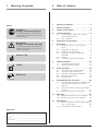
1. Meaning of symbols . . . . . . . . . . . . . . . . . . .2
2. Table of contents . . . . . . . . . . . . . . . . . . . . . .2
3. General safety advice . . . . . . . . . . . . . . . . . .3
4. Product overview . . . . . . . . . . . . . . . . . . . . .4
4.1 Comfort 220.2, 250.2, 252.2, 250.2
speed supply package . . . . . . . . . . . . . .4
4.2 Door variations . . . . . . . . . . . . . . . . . . .6
5. Preparation for mounting . . . . . . . . . . . . . .6
6. Installation . . . . . . . . . . . . . . . . . . . . . . . . . . .7
6.1 Installing the motor unit and drive
boom . . . . . . . . . . . . . . . . . . . . . . . . . . .7
6.2 Installation on the door . . . . . . . . . . . . .8
6.3 Installation on the ceiling . . . . . . . . . . . .9
6.4 Lighting, signal light connection
(optional) . . . . . . . . . . . . . . . . . . . . . . . .9
6.5 Release . . . . . . . . . . . . . . . . . . . . . . . .10
6.6 Connection of control elements . . . . .11
7. Hand transmitter . . . . . . . . . . . . . . . . . . . . .13
7.1 Operation and accessories . . . . . . . . . .13
7.2 Hand transmitter coding . . . . . . . . . . .13
8. Initial operation . . . . . . . . . . . . . . . . . . . . . .14
8.1 Connecting the operator system . . . . .14
8.2 Overview of the control unit . . . . . . . .15
8.3 Overview of the display functions . . . .15
8.4 Express programming . . . . . . . . . . . . . .16
8.5 Function test . . . . . . . . . . . . . . . . . . . .18
9. Extended operator functions . . . . . . . . . . .20
9.1 Programming structure for extended ope-
rator functions (Example for Level 2,
Menu 2) . . . . . . . . . . . . . . . . . . . . . . . .20
9.2 General overview of the programmable
functions . . . . . . . . . . . . . . . . . . . . . .21
9.3 Functions overview for the levels . . . . .23
10. Messages . . . . . . . . . . . . . . . . . . . . . . . . . . .33
10.1 Malfunctions without error messages . .33
10.2 Malfunctions with error messages . . . .34
11. Attachment . . . . . . . . . . . . . . . . . . . . . . . . .36
11.1 Technical Data for Comfort 220.2, 250.2,
252.2, 250.2 speed . . . . . . . . . . . . . . .36
11.2 Declaration of incorporation . . . . . . . .37
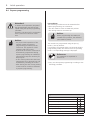
Caution!
Danger of personal injury!
The following safety advice must be
observed at all times so as to avoid
personal injury!
Attention!
Danger of material damage!
The following safety advice must be
observed at all times so as to avoid
material damage!
Advice / Tip
Check
Reference
i
Advice
Type plate
Type: ________________________________________________
Art. No.: _____________________________________________
Product No.: __________________________________________
2. Table of contents
2 Installation and Operating Instructions, Comfort 220.2, 250.2, 252.2, 250.2 speed GB (#83988)
1. Meaning of symbols

3. General safety advice
Please read carefully!
Target group
This operator system may only be installed, connected and put into
operation by qualified and trained professionals!
Qualified and trained specialist personnel are persons
- who have knowledge of the general and special safety regulations,
- who have knowledge of the relevant electro-technical regulations,
- with training in the use and maintenance of suitable safety equipment,
- who are sufficiently trained and supervised by qualified electricians,
- who are able to recognise the particular hazards involved when
working with electricity,
- with knowledge regarding applications of the EN 12635 standard
(installation and usage requirements).
Warranty
For an operations and safety warranty, the advice in this instruction
manual has to be observed. Disregarding these warnings may lead
to personal injury or material damage. If this advice is disregarded,
the manufacturer will not be liable for damages that might occur.
Batteries, fuses and bulbs are excluded from warranty.
To avoid installation errors and damage to the door and operator
system, it is imperative that the installation instructions are followed.
The system may only be used after thoroughly reading the respective
mounting and installation instructions.
The installation and operating instructions are to be given to the
door system user, who must keep them safe.
They contain important advice for operation, checks and maintenance.
This item is produced according to the directives and standards
mentioned in the Manufacturer's Declaration and in the Declaration
of Conformity. The product has left the factory in perfect condition
with regard to safety.
Power-operated windows, doors and gates must be checked by an
expert (and this must be documented) before they are put into
operation and thereafter as required, but at least once a year.
Correct use
The operator system is designed exclusively for opening and closing
garage doors.
The operator must be used in a dry place.
The maximum push and pull force must be observed.
Door requirements
The door must:
- stand still alone (by balance of springs),
- run smoothly.
Beside the advice in these instructions, please observe the
general safety and accident prevention regulations!
Our sales and supply terms and conditions are effective.
Information on installing the operator system
• Ensure that the door is in good mechanical condition.
• Ensure that the door can stop in any position.
• Ensure that the door can be easily moved in the OPEN and CLOSE
directions.
• Ensure that the door opens and closes properly.
• Remove all unnecessary components from the door (e.g. cables,
chains, brackets).
• Render any installations inoperable that will no longer be needed
after the operator system has been installed.
• Before commencing cabling works it is very important to disconnect
the operator system from the electricity supply.
Ensure that the electricity supply remains disconnected throughout
the cabling works.
• Adhere to the local protection regulations.
• Lay the electricity supply cables and control cables; these MUST be
laid separately. The controls voltage is 24 V DC.
• Install the operator system with the door in the CLOSED position.
• Install all the impulse transmitters and control devices (e.g. remote
control buttons) within sight of the door and at a safe distance
from the moving parts of the door. A minimum installation height
of 1.5 m must be observed.
• Permanently fix the warning signs, which advise of the danger of
becoming trapped, at conspicuous locations.
• Ensure that no part of the door extends across public footways or
roads when the installation is complete.
Information on commissioning the operator system
After initial operation, the persons responsible for operating the door
system, or their representatives must be familiarised with the use of
the system.
• Make sure that children cannot access the door control unit.
• Before moving the door, make sure that there are neither persons
nor objects in the operating range of the door.
• Test all existing emergency command devices.
• Never insert your hands into a running door or moving parts.
• Pay attention to any parts of the door system that could cause
crushing or shearing damage or accidents.
The EN 13241-1 regulations must be observed.
Information on servicing the operator system
To ensure proper operation, the following items must be checked
regularly and repaired if necessary.
Before any works to the door system are undertaken, the operator
system must be disconnected from the mains.
• Check once a month to ensure that the operator system reverses
if the door encounters an obstacle.
Depending on the operational direction of the door, place a
50 mm high/wide obstacle in its path.
• Check the settings of the OPEN and CLOSE automatic cut-out
function.
• Check all movable parts of the door and operator system.
• Check the door system for signs of wear or damage.
• Check whether the door can be easily moved by hand.
Information on cleaning the operator system
Never use water jets, high pressure cleaners, acids or bases for
cleaning.
Installation and Operating Instructions, Comfort 220.2, 250.2, 252.2, 250.2 speed GB (#83988) 3

4 Installation and Operating Instructions, Comfort 220.2, 250.2, 252.2, 250.2 speed GB (#83988)
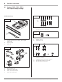
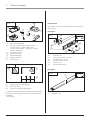
4.1 Comfort 220.2, 250.2, 252.2,
250.2 speed supply package
4. Product overview
1 Comfort 220.2, 250.2, 252.2, 250.2 speed
motor unit
2 Support plate
3 Door link
4 Boom clamps (2x)
5 Suspension cramps (2x)
6 Door connector element
7 Door link bracket (2x)
8 Fixing materials for the boom
11 Screw 6 x 14 (4x)
12 Hexagonal head screw M6 x 20 (2x)
13 Self-tapping screw 6.3 x 16 (4x)
14 Bolt A8 with locking plate
Standard package
9 Adapter sleeve
10 Screw 4.0 x 10
4.1 / 1
1
2
3
4
7
6
4.1 / 2
5
4.1 / 3
8
4.1 / 4
!¯9
4.1 / 5
!1
!”
!#
!£

Installation and Operating Instructions, Comfort 220.2, 250.2, 252.2, 250.2 speed GB (#83988) 5
4. Product overview
15 Mini hand transmitter
16 Micro hand transmitter (only in case of
Comfort 250.2, Comfort 252.2 and
Comfort 250.2 speed – subject to country-
specific alterations)
17 Transmission plug
18 Sun visor clip flap
19 Attachment piece
20 Modular antenna
21 Sun visor clip
25 Operator rail
26 Lintel joining plate, rail type 1
27 Screw B4 4.2 x 13 (2x)
28 Securing sleeve, short
29 Bolt 8 x 12.5
30 M6 nut, self-locking
22 Warning sign for disengaging
23 Warning sticker
24 Sticker for express programming
In addition to the components included in the standard
package, the following accessories are required for the
installation:
- drive boom
Drive booms
The motor unit can be combined with various types of
drive boom.
Rail type 1
31 Operator rail
Rail type 2
4.1 / 6
„1
!5
!6
!7
!8
!9
„¯
4.1 / 7
„” „#
„£
4.1 / 9
§1
4.1 / 8
„·
§¯
„˜
„
7
„5
„6

4. Product overview
6 Installation and Operating Instructions, Comfort 220.2, 250.2, 252.2, 250.2 speed GB (#83988)
Attention!
In order to guarantee correct
mounting, carry out the following
checks before installing.
Supply package
• Check the package to ensure that all the parts are
included.
• Check that you have all the additional components
that are necessary for your particular installation
requirements.
Garage
• Check whether your garage has a suitable mains
connection and a mains disconnection facility.
Door system
5. Preparation for mounting
Attention!
For garages without a second entrance:
the garage door must be fitted with an
emergency release system to allow
access to the garage if a fault occurs.
If a release kit is used:
• Check that the door locks are functioning correctly.
The door locks may not be disabled under any
circumstances.
If a release kit is not used:
• Dismantle or disable the door locks.
• Check that the door to be operated fulfils the
following conditions:
- the door must be easily moveable by hand,
- the door should automatically remain in every
position into which it was moved.
Reference:
When using and installing accessories,
always observe the specific instructions
included with the equipment.
i
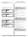
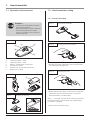
4.2 Door variations
4.2 / 1
The standard package with the appropriate operator
boom is suitable for the following types of door.
Swing out retractable up-and-over door
4.2 / 2
Sectional door, up to 3 m wide
Non-swing out retractable up-and-over door
4.2 / 3
Special accessories are necessary for the following door
type.
4.2 / 4
Sectional door, greater than 3 m wide

Installation and Operating Instructions, Comfort 220.2, 250.2, 252.2, 250.2 speed GB (#83988) 7
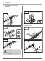
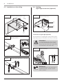
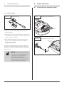
Install door link.
Release sliding carriage.
6.1 Installing the motor unit and
drive boom
6. Installation
Attention!
The drive boom (C) must be carefully
mounted on the motor unit (F).
Do not use force, as this could damage
the gear teeth!
6.1 / 1
2
2
1
Installation, rail type 1
6.1 / 3
1. Push the adapter sleeve onto the drive shaft.
2. Mount the rail on the motor housing.
1. Fit securing sleeve.
2. Install lintel joining plate
1
1. Fit release pin.
2. Install door link
6.1 / 5
21
Installation, rail type 2
1. Fit securing sleeve
2. Install lintel joining plate
6.1 / 6
2
1
6.1 / 2
6.1 / 4

8 Installation and Operating Instructions, Comfort 220.2, 250.2, 252.2, 250.2 speed GB (#83988)
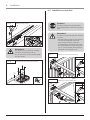
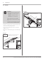
Installation on the up-and-over door.
10 - 50 mm
Installation on the sectional door.
10 - 50 mm
Caution!
The drive system must be prevented
from falling before it has been properly
fixed.
Attention!
In order to ensure that the door balance
is correct:
- the lintel joining plate for the operator
rail must be mounted at the mid
point, above the door connector,
-
at the highest point reached by the door,
the upper edge of the door leaf must
be 10 - 50 mm below the horizontal
underside of the operator rail.
6.2 / 1
6.2 / 2
6.2 Installation on the door
1. Push the adapter sleeve onto the drive shaft.
2. Mount the rail on the motor housing.
Release sliding carriage.
Attention!
The drive boom (C) must be carefully
mounted on the motor unit (F).
Do not use force, as this could damage
the gear teeth!
6.1 / 7
6.1 / 8
2
1
6. Installation

Installation and Operating Instructions, Comfort 220.2, 250.2, 252.2, 250.2 speed GB (#83988) 9
Mount the suspension cramps at the
mounting positions.
15°- 30°
6.3 / 2
1
3
2
3
2
1
Determine mounting positions 1 and 2.
6.3 / 1
6. Installation
Bend the support plate and fix it to the ceiling.
6.3 / 3
1. Fit energy saving bulb.
2. Screw on lamp cover.
6.4 / 1
6.4 Lighting,
signal light connection (optional)
1
2
Connection of signal light (optional)
Connect signal light.
Reference:
The programming of the signal light is
described in level 1, menu 7 and in
level 3, menu 7.
i
Attention!
To avoid damaging the cable insulation,
the cable must be laid in such a way
that it does not come into contact with
the illuminant in the motor unit.
6.4 / 2
The connection of a signal light is only possible with a
signal light relay (not included in the scope of delivery).
6.3 Installation on the ceiling

6. Installation
6.5 Release
• Construct a physical barrier to limit the extent of the
door travel in the opening direction.
• Check that the release pull cord is at a minimum
height of 1.8 m.
• Attach the “release warning sign” to the release pull
cord.
Caution!
- Uncontrolled door movements may
occur when the release function is
activated:
- if the door springs are weak or
broken;
- - or if the door is not balanced.
When opening the door manually,
the carriage can collide with the motor
unit.
If the door has been released, it should
only be moved at a moderate speed!
1. Disconnect door from the motor unit.
2. Reconnect door and motor unit.
6.5 / 1
2
1
Rail type 1
1. Disconnect door from the motor unit.
2. Reconnect door and motor unit.
6.5 / 2
2
1
Rail type 2
10 Installation and Operating Instructions, Comfort 220.2, 250.2, 252.2, 250.2 speed GB (#83988)
1
2
1
2

6. Installation
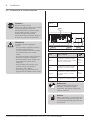
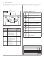
6.6 Connection of control elements
Attention!
In order to avoid damaging the
controls:
- The local safety regulations must be
complied with at all times.
- It is very important that mains cables
are laid separately from control
cables.
- The controls voltage must be 24 V DC.
- If external voltages are applied at
terminals XP020, XB10 or XB01, the
entire electronic system will be
destroyed.
- Only potential-free normally open
contacts may be connected to
terminals 1 and 2 (XB01).
- The shorting plug should never be
plugged into the XP020 system socket!
Caution!
Danger of electric shock:
Before any cabling works begin, it must
be ensured that the cables are
disconnected from the power supply.
During cabling works, it must be
ensured that the cables remain
disconnected from the power supply at
all times (e.g. prevent reconnection).
Reference:
When installing external control
elements, or safety and signal
equipment, the relevant instructions
must be observed.
i
Advice:
Before connecting a control element to
the terminals with system sockets, the
corresponding shorting plug must first
be removed.
3127071
XB10
XB01
XP020
6.6 / 1
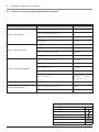
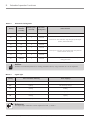
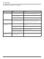
Label Type / function
i
XB01
Connection of external control
elements without system cabling
and two-wire photocell
6.6 / 2,
9.3 /
Level 5 /
Menu 1
XB10
Connection of external control
elements with system cabling
-
XP020
Connection of system photocell
or adapter cable for modular
antenna
9.3 /
Level 8
XB70 Connection of modular antenna 8.1
XB70
Installation and Operating Instructions, Comfort 220.2, 250.2, 252.2, 250.2 speed GB (#83988) 11

6. Installation
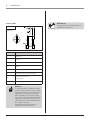
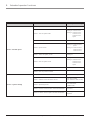
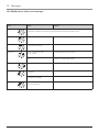
Terminal XB01
Advice:
If a photocell with a standard function
or door frame function is used, it must
be disconnected from the mains before
installing it and taking it into service.
After switching on the mains voltage,
the photocell is only detected automati-
cally by the controls if the path of the
photocell beam remains uninterrupted
for at least 5 seconds.
Otherwise the photocell must be
programmed after installation.
Label Type / function
1 GND (0 V)
2 Impulse
3 24 V DC (max. 50 mA)
70 GND
70 + 71 Two-wire photocell
RX Receiver for the two-wire photocell
Sb1
External impulse button
(if applicable)
TX Transmitter for the two-wire photocell
6.6 / 2
M08E004
12 Installation and Operating Instructions, Comfort 220.2, 250.2, 252.2, 250.2 speed GB (#83988)
Reference:
The programming of the photocell is
explained in section 8.4.
i

Connect hand transmitter.
7.2 Hand transmitter coding
7.2.1 Transfer the coding
• Actuate the master transmitter and hold the button.
The transmitter LED lights up.
• Whilst keeping the button on the master transmitter
depressed, press the desired button on the other
hand transmitter. The LED flashes.
After 1 - 2 seconds, the LED on the newly programmed
transmitter lights up permanently. The programming
procedure is complete.
• Remove the transmission plug.
7.2.1 / 1
Operating the master transmitter.
Transferring the code.
7.2.1 / 2
7.2.1 / 3
1
Caution!
- Children are not allowed to operate
the hand transmitters!
- Before operating the hand transmitter,
make sure that there are neither
persons nor objects in the operating
range of the door.
A Operating button - large
B Operating button - small
C Battery - transmission control light
D Transmission socket
E Reverse side of the hand transmitter
F Battery 3V CR 2032
Overview.
Accessory sun visor clip.
7.1 / 1
A
D
C
B
D
E
F
7.1 / 3
Replace battery.
7.1 / 2
Installation and Operating Instructions, Comfort 220.2, 250.2, 252.2, 250.2 speed GB (#83988) 13
7.1 Operation and accessories
7. Hand transmitter

7. Hand transmitter
14 Installation and Operating Instructions, Comfort 220.2, 250.2, 252.2, 250.2 speed GB (#83988)
Plugging in the module antenna.
8.1 / 1
8.1 Connecting the operator system
Connecting to the power supply.
8.1 / 2
• Connect one end of the transmission plug to the
hand transmitter.
• At the free end of the transmission plug, short-circuit
one of the outer pins with the centre pin adjacent to
it (e.g. using a screw driver).
• Press the desired button on the hand transmitter.
A new code is then generated by the integrated
random coding facility.
The LED flashes quickly.
As soon as the LED lights up permanently, the hand
transmitter has been programmed with a new code.
The button can then be released and the transmission
plug removed.
Advice:
- After the hand transmitter has been
re-programmed, the operator system
must also be re-programmed to
respond to the new code.
- For multi-channel transmitters, the
programming process must be carried
out for each button separately.
Changing the code.
7.2.2 / 1
7.2.2 Change coding
8. Initial operation

Installation and Operating Instructions, Comfort 220.2, 250.2, 252.2, 250.2 speed GB (#83988) 15
P
1
2
3
4
5
6
7
8
1
2
A
B
D
C
Operating elements
Label Type / function
i
A Carousel display 8.3
B
OPEN button (+)
(e.g. to drive the door to
the OPEN position or to
increase parameters when
programming)
-
C
CLOSE button (-)
(e.g. to drive the door to
the CLOSED position or to
decrease parameters when
programming)
-
D
Button (p)
(e.g. to switch to
programming mode or
to save parameters)
-
Overview of the control unit.
8.2 / 1
8. Initial operation
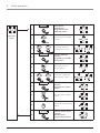
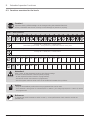
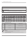
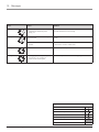
8.3 Overview of the display functions
LED displays in operating mode
Photocell or the CESD has been interrupted
Door moving towards OPEN position
Door in OPEN position
Door is at intermediate position
Door moving towards CLOSED position
Door in CLOSED position
Reference point is switched
Permanent actuation of an external control
element
Remote control is actuated
Ready for operation
Legend:
LED off
LED on
LED flashes slowly
LED pulses
LED flashes quickly
Factory default setting
Not possible –
8.2 Overview of the control unit

16 Installation and Operating Instructions, Comfort 220.2, 250.2, 252.2, 250.2 speed GB (#83988)
8. Initial operation
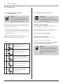
8.4 Express programming
The controls are programmed using the plus (+),
minus (-) and (P) buttons.
If no buttons are pressed within 120 seconds while in
programming mode, the controls revert to operating
mode. A corresponding message is displayed.
Reference:
The messages are explained in
Section 10.
i
Preconditions
The following conditions must be assured before
express programming can commence:
- the door must be in the CLOSED end position.
- the carriage must be connected up.
Advice:
When programming the OPEN and
CLOSED door positions, the reference
point must be passed.
• Carry out the express programming according to the
following procedure.
Advice:
- For proper initial operation of the
operator system, the express
programming procedure must be
carried out. This applies for initial
operation and after a reset.
- A photocell in the door frame area is
automatically programmed during
express programming. No additional
programming steps are necessary for
this purpose.
- A door frame position that has been
programmed for a photocell can only
be deleted by resetting the control.
- After altering the door frame position,
a reset must be carried out followed
by express programming.
Attention!
To ensure correct operation, the path of
the photocell beam must not be inter-
rupted during the express programming
procedure.
Exception: The door leaf in conjunction
with a photocell in the door frame
area.
Legend:
LED off
LED on
LED flashes slowly
LED pulses
LED flashes quickly
Factory default setting
Not possible –

Installation and Operating Instructions, Comfort 220.2, 250.2, 252.2, 250.2 speed GB (#83988) 17
Operating
mode
1.
P
1x >2s <10s
Start express
programming /
Programme the door
OPEN end position
2.
Drive the door to the OPEN
position
3.
Correct the OPEN door
position using (+) and (–)
4.
P
1x <1s
Save the OPEN door
position /
Programme the CLOSED
door position
5.
Drive the door to the
CLOSED position
6.
Correct the CLOSED door
position using (+) and (–)
7.
P
1x <1s
Save the CLOSED door
position /
Programme the remote
control
8.
Press the hand transmitter
button
9.
Release the hand transmitter
button
10.
P
1x <1s
Save the remote control
settings /
End the express
programming procedure
8. Initial operation

18 Installation and Operating Instructions, Comfort 220.2, 250.2, 252.2, 250.2 speed GB (#83988)
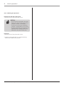
8. Initial operation
Caution!
The automatic cut-out must be
correctly programmed for the CLOSE
and OPEN directions to prevent damage
to persons or property.
The operator system determines the maximum required
driving power during the first two runs after setting
the end positions of the door.
• Operate the operator system (with the door coupled)
to drive the door once from the CLOSED position to
the OPEN position and back to the CLOSED position
without interruption.
During this learning run, the operator system
determines the maximum push and pull forces and the
reserve power required to move the door.
1.
After pressing the (+) button:
The door must open and travel to the
saved OPEN end position.
2.
After pressing the (–) button:
The door must close and travel to the
saved CLOSED end position.
3.
After pressing the hand transmitter
button: The operator system must move
the door in either the OPEN or CLOSE
direction.
4.
After pressing the hand transmitter
button while the operator system is
running:
The operator system must stop.
5.
When the button is pressed again,
the operator system moves in the
opposite direction.
8.5.2 Checking the automatic cut-out
Check:
After express programming and after
making changes to the programming
menu, the following learning runs and
checks must be carried out.
Automatic cut-out, OPENING
For drive systems where the door has openings in the
door wing (diameter of opening > 50 mm):
• Apply a load of 20 kg to the middle of the lower
edge of the door whilst the door is running.
The door must stop immediately.
Automatic cut-out, CLOSING
• Place a 50 mm high obstacle on the ground.
• Drive the door towards the obstacle.
The drive system must stop and reverse when it
comes into contact with the obstacle.
8.5 Function test
8.5.1 Learning run for determining
the driving power
Advice:
The parameter settings are still saved
if the power supply is disconnected.
Only a reset causes the driving power
settings for the OPEN and CLOSE
directions to revert to the factory
settings.
Test:

8. Initial operation
Installation and Operating Instructions, Comfort 220.2, 250.2, 252.2, 250.2 speed GB (#83988) 19
Photocell in the door frame area
• Activate each of the photocells in turn.
Advice:
- The photocell connected in the door
frame area must function above the
position in which it is installed.
The function below the installation
position is suppressed by the control.
- If several photocells are connected, all
photocells react analogue with any
photocell in the door frame area.
Photocell
• Activate each of the photocells in turn.
• Check all photocells that are connected directly
before the CLOSED door position.
8.5.3 Checking the photocell

20 Installation and Operating Instructions, Comfort 220.2, 250.2, 252.2, 250.2 speed GB (#83988)
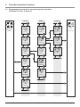
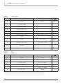
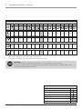
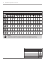
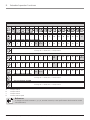
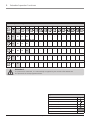
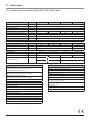
9.1 Programming structure for extended operator functions
(Example for Level 2, Menu 2)
End
programming
ParameterMenuLevels
Level 3
Level 4
Menu 3
Menu 2
Menu 1
Menu-Exit
(Level 2)
Level 2
Level 1
Levels-Exit
Level 8
> 10 sec.
Menu 8
Parameter
Operating
mode
+
-
+
-
+
-
+
-
+
-
+
-
+
-
+
-
+
-
> 5 sec.
+
-
+
-
+
-
+
-
+
-
+
-
+
-
+
-
> 5 sec.
> 5 sec.
Higher value
Lower value
9. Extended operator functions
Page is loading ...
Page is loading ...
Page is loading ...
Page is loading ...
Page is loading ...
Page is loading ...
Page is loading ...
Page is loading ...
Page is loading ...
Page is loading ...
Page is loading ...
Page is loading ...
Page is loading ...
Page is loading ...
Page is loading ...
Page is loading ...
Page is loading ...
Page is loading ...
-
 1
1
-
 2
2
-
 3
3
-
 4
4
-
 5
5
-
 6
6
-
 7
7
-
 8
8
-
 9
9
-
 10
10
-
 11
11
-
 12
12
-
 13
13
-
 14
14
-
 15
15
-
 16
16
-
 17
17
-
 18
18
-
 19
19
-
 20
20
-
 21
21
-
 22
22
-
 23
23
-
 24
24
-
 25
25
-
 26
26
-
 27
27
-
 28
28
-
 29
29
-
 30
30
-
 31
31
-
 32
32
-
 33
33
-
 34
34
-
 35
35
-
 36
36
-
 37
37
-
 38
38


Marantec Comfort 250.2 Owner's manual
- Category
- Garage Door Opener
- Type
- Owner's manual
- This manual is also suitable for
Ask a question and I''ll find the answer in the document
Finding information in a document is now easier with AI
Related papers
-
Marantec Comfort 250 Owner's manual
-
-
Marantec Comfort 250 Owner's manual
-
-
Marantec Control 25 Owner's manual
-
Marantec Control 14 Owner's manual
-
Marantec Parc 100 Owner's manual
-
-
-
Other documents
-
 Cardale DC 650 T Installation Instructions Manual
-
Sony SRSXB10/BLK User guide
-
 Seip TS Series Installation guide
-
 Seip Solar FR I Installation guide
-
atomi smart AT1348 Operating instructions
-
-
Sommer AB6010 Owner's manual
-
York UL R134A User manual
-
Marathon tiga 800 SL Operating instructions
-


