Page is loading ...

© 2013 UTC Fire & Security Americas Corporation, Inc. 1 / 2 P/N P-047550-1871-EN • REV 04 • ISS 30APR13
7007B-N5 Audible/Visible Signal-Strobe
Installation Sheet
Description
The 7007B-N5 series audible/visible signal-strobes are UL
Listed for general purpose signaling applications.
Table 1: Models
Number Description
7007BA-N5 Amber lens
7005BB-N5 Blue lens
7007BG-N5 Green lens
7007BR-N5 Red lens
7007B-N5 Clear lens
Installation
WARNINGS
• Electrocution hazard. A qualified electrician familiar with
National Electrical Code and local code requirements must
install this product. Failure to follow the safety precautions
in this installation sheet could result in product or property
damage, or severe personal injury or death.
• Electrocution hazard. To reduce the risk of shock, do not
remove the lens or tamper with the unit when the circuit is
energized. Disconnect power and allow five (5) minutes for
stored energy to dissipate before starting work or
disassembly. High energy could be stored in the strobe
circuit once it is energized.
The signal-strobe (Figure 1) can be mounted on a Listed
single-gang 2 × 4 in. (51 × 102 mm) electrical box,
double-gang 4 × 4 in. (102 × 102 mm) electrical box, or
standard 4 × 4 in. (102 × 102 mm) junction box with a plaster
ring.
To install the signal-strobe:
1. Install an appropriate electrical box using suitable
hardware.
2. Connect the wire leads as shown in Figure 2.
3. Mount the device to the electrical box. Secure it using two
screws (supplied).
4. Perform an operational test.

2 / 2 P/N P-047550-1871-EN • REV 04 • ISS 30APR13
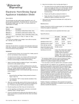
Figure 1: Details of 7007B-N5
Wiring
See Figure 2 for wiring connections.
Figure 2: Wiring connections
Maintenance
WARNING: Electrocution hazard. To reduce the risk of shock,
do not remove lens or tamper with unit when the circuit is
energized. Disconnect power and allow five (5) minutes for
stored energy to dissipate before starting work or disassembly.
High energy could be stored in the strobe circuit once it is
energized.
Perform regularly scheduled testing at least twice a year or
more often as dictated by local authorities having jurisdiction.
Specifications
Operating voltage 120V 60 Hz
A
larm current 115 mA
Regulatory information
Manufacturer Edwards, A Division of UTC Fire & Security
Americas Corporation, Inc.
8985 Town Center Parkway, Bradenton, FL
34202, USA
North American
standards
UL 464, UL 1638
Contact information
For contact information, see www.edwardssignaling.com.
Front
view
Horn
Mounting
screws
Strobe
4 1/2 in.
(114 mm)
4 9/16 in.
(116 mm)
Back
view
To separate 120 VAC
power source
/