Page is loading ...

P-047550-1777 ISSUE 1 © 1998
CHESHIRE, CT 203-699-3000 FAX 860-677-7746
Installation Instructions for
Electronic Strobe Signals
EDWARDS
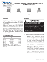
Description
The strobes are high quality signals intended for indoor use. It is
recommended that these products be installed in accordance with
the requirements in the latest edition of national and local electri-
cal codes.
See Table 2 and Figure 1 for specifications.
Table 1. Electronic Strobes
Installation
1. Install an appropriate electrical box as listed below using
suitable hardware (provided by others).
For Flush Mount: 1 gang Handy box, Iberville 1104 style, or
equivalent.
For Surface Mount: Surface Box, Part Number P-047701-
0232 and (2) Conduit Plugs (all supplied).
2. Bring signaling circuit field wiring into the electrical box.
-AQ Models -N5 Models
Operating Voltage 24V 50/60 Hz, 24V DC 120V 50/60 Hz
Operating Current 390 mA 87 mA
Flash Rate (per second) 1 fps
Operating Environment Indoor 85% relative humidity @ 86°F (30°C), 32° to 120°F (0° to 49°C) variable ambient temperature.
NOTE: Cat. No. 89STR(*)-AQ and Cat. No. 89SMSTR(*)-AQ potentially generate timing signals or pulses above 9 kHz and therefore have been tested
and found to comply with the limits for a Class A digital device, pursuant to Part 15 of the FCC Rules. These limits are designed to provide reasonable
protection against harmful interference when the equipment is operated in a commercial environment. This equipment generates, uses and can radiate
frequency energy and, if not installed and used in accordance with the instruction manual, may cause harmful interference to radio communications.
Operation of this equipment in a residential area is likely to cause harmful interference in which case the user will be required to correct the interference
at his own expense.
CAUTION: Changes or modifications to this equipment not expressly approved by the party responsible for compliance could void the user's authority to
operate the equipment.
Table 2. Specifications
Catalog Number Voltage Description
89STR(*)-AQ 24V AC/DC Strobe, Flush Mount
89STR(*)-N5 120V AC
89SMSTR(*)-AQ 24V AC/DC Strobe, Surface Mount
89SMSTR(*)-N5 120V AC
*Insert Lens Color: C-clear, R-red, G-Green, B-blue or A-amber.
WARNINGS
To reduce the risk of shock, do not connect power
to the strobe until directed in these instructions.
To reduce the risk of shock, do not tamper with unit
when circuit is energized. Disconnect all power
and allow 5 minutes for stored energy to dissipate
before handling.
CAUTION
This unit is not serviceable or repairable. Should
the unit fail to operate, contact the supplier for
replacement.
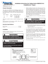
3. (Figure 1) Position the mounting plate onto the electrical
box. Fasten the plate using two pan head slotted screws
(supplied).
4. For indoor surface mounting, ensure all conduit holes are
plugged.
5. (Figure 2) Connect the strobe wiring terminals on the unit to
a signal circuit that outputs a constant (not pulsed) voltage.
Polarity must be observed for units operating on 24V DC.
6. After connections are complete, mount the unit onto the
mounting plate. Fasten it using two countersunk Phillip head
screws (supplied).
7. Apply power and activate the strobe unit to verify that it is
operating properly.
Maintenance
Perform a visual inspection and an operational test twice a year.

Figure 1. Mounting Arrangements
Figure 2. Electrical Connections
To Power
Source
-
+
Note: Polarity must be observed for units operating on 24 VDC.
P-047550-1777 ISSUE 1
/