Page is loading ...

Diaphragm Metering Pump
ProMinent
®
Makro/ 5 M5Ma
Operating instructions
Two sets of operating instructions are required for the safe, correct and proper operation of the metering pumps: The
product-specific operating instructions and the "General Operating Instructions for ProMinent
®
motor-driven metering
pumps and hydraulic accessories".
Both sets of operating instructions are only valid when read together.
Original Operating Instructions (2006/42/EC)Part no. 985753 BA MAK 005 10/11 EN
Please carefully read these operating instructions before use! · Do not discard!
The operator shall be liable for any damage caused by installation or operating errors!
Technical changes reserved.

985754, 1, en_GB
© 2010
ProMinent Dosiertechnik GmbH
Im Schuhmachergewann 5-11
69123 Heidelberg
Germany
Telephone: +49 6221 842-0
Fax: +49 6221 842-617
email: [email protected]
Internet: www.prominent.com
2

Read the following supplementary information in its entirety!
Should you already know this information, you have an even
greater need of the Operating Instructions.
The following are highlighted separately in the document:
n Enumerated lists
Instructions
ð
Outcome of the handling instructions
- see (reference)
Information
This provides important information relating to the cor‐
rect operation of the device or is intended to make
your work easier.
Safety notes
Safety notes are identified by pictograms - see Safety Chapter.
Two sets of operating instructions are required for the safe, correct
and proper operation of the metering pumps: The product-specific
operating instructions and the "General Operating Instructions for
ProMinent
®
motor-driven metering pumps and hydraulic accesso‐
ries".
Both sets of operating instructions are only valid when read
together.
Please read these operating instructions carefully before use! Do
not discard!
Please state identity code and serial number, which you can find
on the nameplate when you contact us or order spare parts. This
enables the device type and material versions to be clearly identi‐
fied.
In order to make it easier to read, this document uses the male
form in grammatical structures but with an implied neutral sense. It
is aimed equally at both men and women. We kindly ask female
readers for their understanding in this simplification of the text.
Supplementary information
Fig. 1: Please read!
General user instructions
State the identity code and serial
number
General non-discriminatory approach
Supplemental instructions
3

Table of contents
1 Identity code.......................................................................... 5
2
About this pump.................................................................... 7
3 Safety chapter....................................................................... 8
4 Storage, transport and unpacking....................................... 14
5 Overview of equipment, control elements........................... 16
6 Functional description......................................................... 19
7 Assembly............................................................................ 21
8 Installation........................................................................... 24
8.1 Installation, hydraulic.................................................. 24
8.2 Installation, electrical.................................................. 26
9 Start up............................................................................... 29
10 During use........................................................................... 31
11 Maintenance....................................................................... 32
12
Repairs................................................................................ 37
12.1 Replacing the membrane.......................................... 38
12.2 Valve repair............................................................... 40
12.2.1 Double ball valves.................................................. 40
12.2.2 Single ball valves................................................... 41
12.2.3 Plate valves........................................................... 42
13 Troubleshooting.................................................................. 45
14 Decommissioning and disposal.......................................... 48
14.1 Decommissioning..................................................... 48
14.2 Disposal.................................................................... 50
15 Technical data..................................................................... 51
15.1 Performance data..................................................... 51
15.2 Accuracy................................................................... 52
15.2.1 Reproducibility....................................................... 52
15.2.2 Metering precision................................................. 52
15.3 Viscosity.................................................................... 52
15.4 Wetted materials....................................................... 53
15.5 Ambient conditions................................................... 53
15.5.1 Temperatures........................................................ 53
15.5.2 Air humidity............................................................ 54
15.6 Housing degree of protection.................................... 54
15.7 Stroke sensor (option), intrinsically safe................... 55
15.8 Filling volumes.......................................................... 55
15.8.1 Gear oil.................................................................. 55
15.9 Sound pressure level................................................ 55
15.10 Compatibility........................................................... 56
15.11 Supplement for modified versions.......................... 56
16 EC Declaration of Conformity............................................. 57
17 Index................................................................................... 59
Table of contents
4

1 Identity code
M5Ma Makro/ 5 diaphragm metering pump
Power end type
H Main power end
D Main power end, doubled
A Add-on power end
B Add-on power end doubled
Type:
bar l/h
041540 4 1540
041900 4 1900
042600 4 2600
043400 4 3400
044000 4 444000
Dosing head material
PC PVC
PV PVDF
TT PTFE + 25 % carbon
SS Stainless steel
Seal material
T PTFE
Displacement body material
T Metering diaphragm with PTFE coating
Dosing head version
1 with valve spring, Hastelloy C; 0.1 bar
Hydraulic connector
0 Standard connection
1 Union nut and PVC insert
2 Union nut and PP insert
3 Union nut and PVDF insert
4 Union nut and SS insert
Version
0
With ProMinent
®
logo, no frame
1
Without ProMinent
®
logo, no frame
A
With ProMinent
®
logo, with single frame
B
With ProMinent
®
logo, with double frame
Identity code
5

M5Ma Makro/ 5 diaphragm metering pump
C
With ProMinent
®
logo, with triple frame
D
With ProMinent
®
logo, with quadruple frame
M Modified* * order-related version, for pump
features see order paperwork
Electric power supply
S 3 ph, 230 V/400 V 50/60 Hz (WBS)
L 3 ph, 460 V, 60 Hz, (Exe, Exd)
P 3 ph, 230 V/400 V 50 Hz (Exe, Exd)
R Variable speed motor 4 pole, 230/400 V (R 1:5)
N 1 ph, 115 V, 60Hz
V(0) Motor with integral frequency converter
V(2) Motor with integral frequency converter (Exd)
Z Speed control 230/400 V assy.
5 No motor, with gear IEC 100
6 No motor, with gear IEC 112
0 No motor, no gear
Motor version
0 IP 55 (Standard) ISO class F
1 Exe version ATEX-T3
2 Exd version ATEX-T4
A Power end ATEX design
Stroke sensor
0 No stroke sensor
1 Stroke sensor (Namur), intrinsically safe
Stroke length adjustment
0 Stroke length adjustment, manual
3 Control drive 230 V 0-20 mA
4 Control drive 230 V 4-20 mA
5 Control drive 115 V 0-20 mA
6 Control drive 115 V 4-20 mAz
Applications
0 standard
Identity code
6

2 About this pump
The ProMinent
®
Makro/ 5 diaphragm metering pump is fitted as
standard with a 3 kW wide range AC motor. The stroke length can
be adjusted between 0...20 mm. The spheroidal graphite housing
can be combined with up to 7 liquid end sizes and 5 gear reduction
ratios (integrated in the spur geared motor). The liquid ends are
available in various material combinations which can be matched
to the feed chemicals being metered.
The ProMinent
®
Makro/ 5 externally mounted metering pump can
be combined with the Makro/ 5 main power end to form a double or
multiple pump. A main power end can be combined with up to four
add-on power ends. One power end can be used both as a single
or a double head version.
The double head versions are fitted with a second liquid end which
operates in push-pull mode (Boxer principle).
All pumps
Externally mounted pumps
Double head version
About this pump
7

3 Safety chapter
The following signal words are used in these operating instructions
to denote different severities of danger:
Signal word Meaning
WARNING Denotes a possibly dangerous
situation. If this is disregarded,
you are in a life-threatening sit‐
uation and this can result in
serious injuries.
CAUTION Denotes a possibly dangerous
situation. If this is disregarded,
it could result in slight or minor
injuries or material damage.
The following warning signs are used in these operating instruc‐
tions to denote different types of danger:
Warning signs Type of danger
Warning – hand injuries.
Warning – high-voltage.
Warning – flammable sub‐
stances.
Warning – hot surface.
Warning – danger zone.
n The pump may only be used to meter liquid metering chemi‐
cals.
n In potentially explosive atmospheres in zone 1, device category
II 2G of explosion group II C, the pump must only be operated
according to the with the relevant nameplate (and the respec‐
tive EC Declaration of Conformity) for pumps for potentially
explosive atmospheres complying with Directive 94/9/EC in
accordance with the European guidelines. The explosion
group, category and degree of protection identified on the
marking must correspond with or be better than the given con‐
ditions in the intended field of application.
Identification of safety notes
Warning signs denoting different
types of danger
Correct and proper use
Safety chapter
8

n The pump may only be started up after it has been correctly
installed and commissioned in accordance with the technical
data and specifications contained in the operating instructions.
n The general limitations with regard to viscosity limits, chemical
resistance and density must be observed - see also ProMinent
resistance list (In the product catalogue or at
www.prominent.com
)!
n Any other uses or modifications are prohibited.
n Pumps without the relevant nameplate (and the respective EC
Declaration of Conformity) for pumps for potentially explosive
atmospheres must never be operated in potentially explosive
atmospheres.
n The pump is not intended for the metering of gaseous media or
solids.
n The pump is not intended for unprotected outside use.
n The pump is only approved to meter flammable liquids, if the
operator takes appropriate safety measures.
n The pump should only be operated by trained and authorised
personnel, see also
Ä ‘Qualification of personnel’ on page 9
.
n You are obliged to observe the information contained in the
operating instructions at the different phases of the device's
service life.
In hazardous locations only the following combinations of identity
code variants is permitted:
Combi‐
nations
Identity code specification values
1 Electric power supply L, P
Motor version 1,2, V(2)
Stroke length adjustment 0, G, H
2 Electric power supply 0, 5.6
Motor version A
Stroke length adjustment 0, G, H
Activity Qualification level
Storage, transport, unpacking Instructed person
Assembly, installation of
hydraulic system
Technical personnel, service
Installation, electrical Electrical technician
Operation Instructed person
Maintenance, repair Technical personnel, service
Qualification of personnel
Safety chapter
9

Activity Qualification level
Decommissioning, disposal Technical personnel, service
Troubleshooting Technical personnel, electrical
technician, instructed person,
service
Explanation of the terms:
Technical personnel
A qualified employee is deemed to be a person who is able to
assess the tasks assigned to him and recognise possible dangers
based on his/her technical training, knowledge and experience, as
well as knowledge of pertinent regulations.
Note:
A qualification of equal validity to a technical qualification can also
gained by several years employment in the relevant work area.
Electrical technician
Electrical technicians are deemed to be people, who are able to
complete work on electrical systems and recognize and avoid pos‐
sible dangers independently based on their technical training and
experience, as well as knowledge of pertinent standards and regu‐
lations.
Electrical technicians should be specifically trained for the working
environment in which the are employed and know the relevant
standards and regulations.
Electrical technicians must comply with the provisions of the appli‐
cable statutory directives on accident prevention.
Instructed person
An instructed person is deemed to be a person who has been
instructed and, if required, trained in the tasks assigned to him/her
and possible dangers that could result from improper behaviour, as
well as having been instructed in the required protective equipment
and protective measures.
Service
Customer Service department refers to service technicians, who
have received proven training and have been authorised by ProMi‐
nent or ProMaqua to work on the system.
WARNING!
Warning of dangerous or unknown feed chemical
Should a dangerous or unknown feed chemical be
used: It may escape from the hydraulic components
when working on the pump.
– Take appropriate protective measures before
working on the pump (e.g. safety glasses, safety
gloves, ...). Observe the safety data sheet for the
feed chemical.
– Drain and flush the liquid end before working on
the pump.
Safety notes
Safety chapter
10

WARNING!
Danger from hazardous substances!
Possible consequence: Fatal or very serious injuries.
Please ensure when handling hazardous substances
that you have read the latest safety data sheets pro‐
vided by the manufacture of the hazardous substance.
The actions required are described in the safety data
sheet. Check the safety data sheet regularly and
replace, if necessary, as the hazard potential of a sub‐
stance can be re-evaluated at any time based on new
findings.
The system operator is responsible for ensuring that
these safety data sheets are available and that they
are kept up to date, as well as for producing an associ‐
ated hazard assessment for the workstations affected.
CAUTION!
Warning of feed chemical spraying around
Feed chemical can spray out of the hydraulic compo‐
nents if they are manipulated or opened due to pres‐
sure in the liquid end and adjacent parts of the system.
– Disconnect the pump from the mains power supply
and ensure that it cannot be switched on again by
unauthorised persons.
– Depressurise the system before commencing any
work on hydraulic parts.
CAUTION!
Warning of feed chemical spraying around
An unsuitable feed chemical can damage the parts of
the pump contacted by the chemical.
– Take into account the resistance of the materials
which will come into contact with the chemical
when selecting the feed chemical - see the ProMi‐
nent product catalogue or under
www.prominent.com
.
CAUTION!
Danger of personnel injury and material damage
The use of untested third party parts can result in per‐
sonnel injuries and material damage.
– Only fit parts to metering pumps, which have been
tested and recommended by ProMinent.
Safety chapter
11

CAUTION!
Danger from incorrectly operated or inadequately
maintained pumps
Danger can arise from a poorly accessible pump due
to incorrect operation and poor maintenance.
– Ensure that the pump is accessible at all times.
– Adhere to the maintenance intervals.
CAUTION!
Warning of illegal operation
Observe the regulations that apply where the unit is to
be installed.
In the event of an electrical accident, disconnect the mains cable
from the mains or press the emergency cut-off switch fitted on the
side of the system!
If feed chemical escapes, also depressurise the hydraulic system
around the pump as necessary. Adhere to the safety data sheet for
the feed chemical.
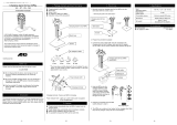
1
6
5
2
3
4
P_MAK_0025_SW
Fig. 2: Isolating protective equipment Makro/ 5 with add-on power
end (shown here for piston version)
1 Cap (only single head version)
2 Fan impeller hood
3 Terminal box cover, motor
4 Cover plate (only with add-on power end)
5 Flange cover
6 Protective cover (only diaphragm and piston versions)
Information in the event of an emer‐
gency
Protective equipment
Safety chapter
12

WARNING!
Warning of personal injury and material damage
– The customer must only remove the protective
equipment if requested to do so by the operating
instructions.
– The pump must not operate without fitted protec‐
tive equipment.
Sound pressure level LpA < 75 dB in accordance with EN ISO
20361:2010-10
at maximum stroke length, maximum stroke rate, maximum back
pressure (water)
Sound pressure level
Safety chapter
13

4 Storage, transport and unpacking
WARNING!
The transporting of pumps which have been used with
radioactive feed chemicals is forbidden!
They will also not be accepted by ProMinent!
WARNING!
Only return metering pumps for repair in a cleaned
state and with a flushed liquid end - refer to the section
on decommissioning!
Only send metering pumps with a filled in Decontami‐
nation Declaration form. The Decontamination Decla‐
ration constitutes an integral part of an inspection /
repair order. A unit can only be inspected or repaired
when a Declaration of Decontamination Form is sub‐
mitted that has been completed correctly and in full by
an authorised and qualified person on behalf of the
pump operator.
You can find the "Decontamination Declaration" form
under
www.prominent.com
or on the CD.
CAUTION!
Danger of environmental and material damage
The unit can be damaged or oil may escape due to
incorrect or improper storage or transportation!
– The unit should only be stored or transported in a
well packaged state - preferably in its original
packaging.
– Only transport the unit with the locking screw - not
the bleed plug - fitted to the oil filling opening.
– The packaged unit should also only be stored or
transported in accordance with the stipulated
storage conditions.
–
The packaged unit should be protected from mois‐
ture and the ingress of chemicals.
Compare the delivery note with the scope of supply:
n Metering pump with mains power cable
n Connector kit for tube/pipe connection
n Product-specific operating instructions with EC Declaration of
Conformity
n CD with order information, exploded diagrams, performance
diagrams, motor data sheet and dimension sheets
n Optional accessories if ordered
Safety notes
Scope of supply
Storage, transport and unpacking
14

Personnel:
n
Technical personnel
1. Place the caps on the valves.
2. Check whether the seal screw is screwed into oil filler
opening instead of the vent screw.
3. Preferably place the pump standing vertically on a pallet and
secure against falling over.
4. Cover the pump with a tarpaulin cover - allowing rear ventila‐
tion.
Store the pump is a dry, sealed place in the following ambient con‐
ditions.
Data Value Unit
Minimum storage and transport tem‐
perature
-10 °C
Maximum storage and transport tem‐
perature
+50 °C
Maximum air humidity * 95 % rel.
humidity
* non-condensing
Storage
Ambient conditions
Storage, transport and unpacking
15

5 Overview of equipment, control elements
P_MAK_0027_SW
1
2
3
1
4
A
5
C
Fig. 3: View from the motor side (here M5Ka H)
A Power end
C Liquid end
1 Lifting eye
2 Stroke length adjustment wheel
3 Indicating dial
4 motor
5 Oil drain plug
P_MAK_0027_SW
7
6
Fig. 4: View away from the motor (here M5Ka H)
6 Vent screw
7 Oil inspection window
Power end, single head
Overview of equipment, control elements
16

P_MAK_0029_SW
1 1
2
3
5
C A C
4
Fig. 5: View from the motor side (here M5Ka D)
A Power end
C Liquid end
1 Lifting eye
2 Stroke length adjustment wheel
3 Indicating dial
4 motor
5 Oil drain plug
P_MAK_0030_SW
6
7
Fig. 6: View away from the motor (here M5Ka D)
6 Vent screw
7 Oil inspection window
Power end, double head
Overview of equipment, control elements
17

1
2
5
3
4
P_MAK_0031_SW
Fig. 7
1 Discharge valve
2 Dosing head
3 Suction valve
4 Tube nozzle for leakage
5 Protective cover
Liquid end
Overview of equipment, control elements
18

6 Functional description
The Makro/ 5 metering pump is a motor-driven metering pump with
a kinematic gear.
A motor drives the cam shaft (1). A connecting rod (2) rests on the
cam shaft (1) which allows the oscillating crank (4) to rotate about
a variable pivot point, see
Fig. 8. The lifting arm of the oscillating
crank, which lies above the pivot point, moves the slide rod (8)
which itself drives the liquid end.
The stroke is adjusted using the manual adjustment wheel (7). This
causes a spindle (6) to move the fork (5; shown in cutaway view in
the diagram). The fork (5) moves the sliding block (3) in a groove
cut into the oscillating crank (4). The sliding block (3) determines
the pivot point of the oscillating crank (4). This determines the
stroke length. When the pivot point of the sliding block (3) is
directly above the axle of the slide rod (8) the lifting arm of the
oscillating crank above the pivot point is at zero and the slide rod
stops. When the sliding block (3) is pushed down, the lifting arm of
the oscillating crank (4) above the pivot point is greater than zero
so that the slide rod (8) is driven
Liquid ends can be fitted to both ends of the slide rod. They then
operate in push-pull mode (Boxer principle).
P_MAK_0035_SW
6
5
4
3
1
2
8
7
Fig. 8: Cross-section through the power end
1 Cam shaft
2 Connecting rod
3 Sliding block
4 Oscillating crank
5 Fork
6 Spindle
7 Manual adjustment wheel
8 Slide rod
Power end functional description
Functional description
19

The diaphragm (3) hermetically shuts off the pump volume of the
dosing head (2) from the outside. The suction valve (4) closes as
soon as the diaphragm (3) is moved in to the dosing head (2) and
the feed chemical flows through the discharge valve (1) out of the
dosing head. The discharge valve (1) closes as soon as the
metering diaphragm (3) is moved in the opposite direction due to
the vacuum pressure in the dosing head and fresh feed chemical
flows through the suction valve (4) into the dosing head. One cycle
is thus completed.
1
2
3
4
P_MAK_0036_SW
Fig. 9: Cross-section through the liquid end
1 Discharge valve
2 Dosing head
3 Diaphragm
4 Suction valve
Functional description of the dia‐
phragm liquid end (for M5Ma)
Functional description
20
/