ESAB PT-36 User manual

Category
Welding System
Type
User manual

This manual is also suitable for

PT-36
Mechanized Plasmarc Cutting Torch
Instruction Manual (EN)
0558005239
132
This equipment will perform in conformity with the description thereof contained in this manual and accompa-
nying labels and/or inserts when installed, operated, maintained and repaired in accordance with the instruc-
tions provided. This equipment must be checked periodically. Malfunctioning or poorly maintained equipment
should not be used. Parts that are broken, missing, worn, distorted or contaminated should be replaced imme-
diately. Should such repair or replacement become necessary, the manufacturer recommends that a telephone
or written request for service advice be made to the Authorized Distributor from whom it was purchased.
This equipment or any of its parts should not be altered without the prior written approval of the manufacturer.
The user of this equipment shall have the sole responsibility for any malfunction which results from improper
use, faulty maintenance, damage, improper repair or alteration by anyone other than the manufacturer or a ser-
vice facility designated by the manufacturer.
BE SURE THIS INFORMATION REACHES THE OPERATOR.
YOU CAN GET EXTRA COPIES THROUGH YOUR SUPPLIER.
These INSTRUCTIONS are for experienced operators. If you are not fully familiar with the
principles of operation and safe practices for arc welding and cutting equipment, we urge
you to read our booklet, “Precautions and Safe Practices for Arc Welding, Cutting, and
Gouging,” Form 52-529. Do NOT permit untrained persons to install, operate, or maintain
this equipment. Do NOT attempt to install or operate this equipment until you have read
and fully understand these instructions. If you do not fully understand these instructions,
contact your supplier for further information. Be sure to read the Safety Precautions be-
fore installing or operating this equipment.
CAUTION
USER RESPONSIBILITY
READ AND UNDERSTAND THE INSTRUCTION MANUAL BEFORE INSTALLING OR OPERATING.
PROTECT YOURSELF AND OTHERS!
133
TABLE OF CONTENTS
1.0 Safety Precautions ................................................................................. 135
2.0 Description ........................................................................................ 137
2.1 General . . . . . . . . . . . . . . . . . . . . . . . . . . . . . . . . . . . . . . . . . . . . . . . . . . . . . . . . . . . . . . . . . . . . . . . . . . . . . . . . . . . . . . . . 137
2.2 Scope ......................................................................................... 137
2.3 Package Options Available ..................................................................... 137
2.4 Optional Accessories: ......................................................................... 138
2.5 PT-36 Technical Specications..................................................................141
3.0 Installation......................................................................................... 143
3.1 Connection of Torch To Plasma System ........................................................ 143
3.2 Mounting Torch to Machine ..................................................................144
4.0 Operation ......................................................................................... 145
4.1 Set Up ......................................................................................... 147
4.2 Cut Quality . . . . . . . . . . . . . . . . . . . . . . . . . . . . . . . . . . . . . . . . . . . . . . . . . . . . . . . . . . . . . . . . . . . . . . . . . . . . . . . . . . . 147
4.3 Torch Flow Passages ......................................................................... 152
5.0 Maintenance....................................................................................... 153
5.1 Introduction ................................................................................ 153
5.2 Torch Front End Disassembly.................................................................. 154
5.3 Torch Front End Disassembly (for Production Thick Plate)....................................... 157
5.4 Assembly Of Torch Front End ................................................................ 160
5.5 Assembly of Torch Front End (for Production Thick Plate) ....................................... 161
5.6 Torch Body . . . . . . . . . . . . . . . . . . . . . . . . . . . . . . . . . . . . . . . . . . . . . . . . . . . . . . . . . . . . . . . . . . . . . . . . . . . . . . . . . 163
5.7 Removal and Replacement of the Torch Body.................................................. 164
5.8 Reduced Consumable Life ................................................................... 167
Section / Title Page
134
TABLE OF CONTENTS
135
SECTION 1 SAFETY PRECAUTIONS
1.0 Safety Precautions
Users of ESAB welding and plasma cutting equipment have the ultimate responsibility for ensuring that anyone
who works on or near the equipment observes all the relevant safety precautions. Safety precautions must meet
the requirements that apply to this type of welding or plasma cutting equipment. The following recommendations
should be observed in addition to the standard regulations that apply to the workplace.
All work must be carried out by trained personnel well acquainted with the operation of the welding or plasma
cutting equipment. Incorrect operation of the equipment may lead to hazardous situations which can result in
injury to the operator and damage to the equipment.
1. Anyone who uses welding or plasma cutting equipment must be familiar with:
- its operation
- location of emergency stops
- its function
- relevant safety precautions
- welding and / or plasma cutting
2. The operator must ensure that:
- no unauthorized person stationed within the working area of the equipment when it is started up.
- no one is unprotected when the arc is struck.
3. The workplace must:
- be suitable for the purpose
- be free from drafts
4. Personal safety equipment:
- Always wear recommended personal safety equipment, such as safety glasses, ame proof
clothing, safety gloves.
- Do not wear loose tting items, such as scarves, bracelets, rings, etc., which could become
trapped or cause burns.
5. General precautions:
- Make sure the return cable is connected securely.
- Work on high voltage equipment may only be carried out by a qualied electrician.
- Appropriate re extinquishing equipment must be clearly marked and close at hand.
- Lubrication and maintenance must not be carried out on the equipment during operation.
136
SECTION 1 SAFETY PRECAUTIONS
WELDING AND PLASMA CUTTING CAN BE INJURIOUS TO YOURSELF
AND OTHERS. TAKE PRECAUTIONS WHEN WELDING OR CUTTING. ASK
FOR YOUR EMPLOYER’S SAFETY PRACTICES WHICH SHOULD BE BASED
ON MANUFACTURERS’ HAZARD DATA.
ELECTRIC SHOCK - Can kill.
- Install and earth (ground) the welding or plasma cutting unit in accordance with applicable standards.
- Do not touch live electrical parts or electrodes with bare skin, wet gloves or wet clothing.
- Insulate yourself from earth and the workpiece.
- Ensure your working stance is safe.
FUMES AND GASES - Can be dangerous to health.
- Keep your head out of the fumes.
- Use ventilation, extraction at the arc, or both, to take fumes and gases away from your breathing zone
and the general area.
ARC RAYS - Can injure eyes and burn skin.
- Protect your eyes and body. Use the correct welding / plasma cutting screen and lter lens and wear
protective clothing.
- Protect bystanders with suitable screens or curtains.
FIRE HAZARD
- Sparks (spatter) can cause re. Make sure therefore that there are no inammable materials nearby.
NOISE - Excessive noise can damage hearing.
- Protect your ears. Use earmus or other hearing protection.
- Warn bystanders of the risk.
MALFUNCTION - Call for expert assistance in the event of malfunction.
READ AND UNDERSTAND THE INSTRUCTION MANUAL BEFORE INSTALLING OR OPERATING.
PROTECT YOURSELF AND OTHERS!
WARNING
137
2.2 Scope
The purpose of this manual is to provide the operator with all the information required to install and service
the PT-36 Mechanized Plasmarc Cutting Torch. Technical reference material is also provided to assist in trouble-
shooting the cutting package.
2.3 Package Options Available
PT-36 package options available through your ESAB dealer. See Replacement Parts section for component part
numbers.
2.1 General
The PT-36 Mechanized Plasmarc Cutting Torch is a plasma arc torch factory assembled to provide torch compo-
nent concentricity and consistent cutting accuracy. For this reason, the torch body can not be rebuilt in the eld.
Only the torch front-end has replaceable parts.
SECTION 2 DESCRIPTION
DESCRIPTIONS FOR PT-36 TORCH ASSEMBLY'S PART NUMBER
PT-36 TORCH AY 4.5 ft (1,3m) 0558003849
PT-36 TORCH AY 6 ft (1,8m) 0558003850
PT-36 TORCH AY 12 ft (3,7m) 0558003852
PT-36 TORCH AY 15 ft (4,6m) 0558003853
PT-36 TORCH AY 17 ft (5,2m) 0558003854
PT-36 TORCH AY 25 ft (7,6m) 0558003856
PT-36 TORCH AY 14 ft MINI-BEVEL (4,3m) 0558005741
138
PT-36 Repair & Accessories Kit ...................................................................................0558005221
SECTION 2 DESCRIPTION
2.4.1 PT-36 Torch Consumable Kits
2.4 Optional Accessories:
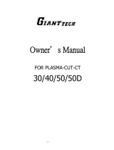
Test Flow Meter - This valuable troubleshooting tool allows measurement of the ac-
tual plasma gas ow through the torch ...............................................................................21317
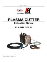
Bubble Muer - When used in conjunction with a water pump recirculating water
from the table and by using compressed air, this device creates a bubble of air which
enables a PT-36 Plasmarc Cutting Torch to be used underwater with slight sacrice
of cut quality. This system also permits operation above water as the ow of water
through the muer reduces fume, noise, and arc U.V. Radiation).
(for installation/operation instructions see manual 0558006722) ............................. 37439
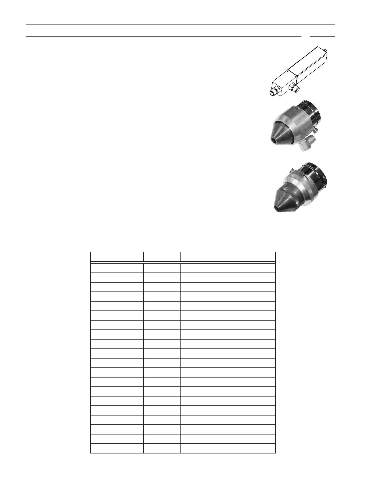
Air Curtain - This device when supplied with compressed air is used to improve the
performance of the PT-36 Plasmarc Cutting Torch when cutting underwater. The de-
vice mounts onto the torch and produces a curtain of air. This allows the plasma arc to
operate in a relatively dry zone, even though the torch has been submerged to reduce
noise, fume, and arc radiation. To be used in underwater applications only.
(for installation/operation instructions see manual 0558006404) .............................37440
Part Number Quantity Description
0558003804 1 Torch Body PT-36 w/O-rings
996528 10 O-ring 1.614 ID x .070
0558002533 2 Bae, 4 Hole x .032
0558001625 2 Bae, 8 Hole x .047
0558002534 1 Bae, 4 x .032 Reverse
0558002530 1 Bae, 8 x .047 Reverse
0558005457 1 Bae, 4 Hole x .022
0558003924 3 Electrode Holder PT-36 w/O-ring
86W99 10 O-ring .364 ID x .070
37082 2 Nozzle Retaining Cup, Standard
21796 1 Shield Gas Diuser, Low Current
21944 5 Shield Gas Diuser, Standard
22496 1 Shield Gas Diuser, Reverse
37081 2 Shield Retainer, Standard
0558003858 2 Contact Ring w/screw
37073 6 Screw, Contact Ring
93750010 2 Hex Key Wrench .109"
996568 1 Nut Driver 7/16" (Electrode tool)
0558003918 1 Electrode Holder Tool PT-36
77500101 1 Silicon Grease DC-111 5.3oz
139
SECTION 2 DESCRIPTION
PT-36 200A Start-up Kit ...............................................................................................0558005222
Part Number Quantity Description
0558003914 8 Electrode O2 UltraLife, Standard
0558003928 3 Electrode N2/H35, Standard
0558005459 3 Electrode O2/N2, Low Current
0558006010 3 Nozzle PT-36 1.0mm (.040")
0558006014 3 Nozzle PT-36 1.4mm (.055")
0558006020 5 Nozzle PT-36 2.0mm (.080")
0558006130 3 Shield PT-36 3.0mm (.120")
0558006141 3 Shield PT-36 4.1mm (.160")
0558008010 3 Nozzle PT-36 1.0mm (.040") PR
0558007624 3 Shield PT-36 2.4mm (.095")
0558006023 3 Nozzle PT-36 2.3mm (.090")
0558006166 3 Shield PT-36 6.6mm (.259")
0558006908 3 Nozzle PT-36 0.8mm (.030")
0558006018 3 Nozzle PT-36 1.8mm (.070")
PT-36 400A Start-up Kit ...............................................................................................0558005223
Part Number Quantity Description
0558003914 5 Electrode O2 UltraLife, Standard
0558007791 5 Electrode, High Current O2
0558003928 3 Electrode N2/H35, Standard
0558005459 3 Electrode O2/N2, Low Current
0558006010 2 Nozzle PT-36 1.0mm (.040")
0558006014 2 Nozzle PT-36 1.4mm (.055")
0558006020 5 Nozzle PT-36 2.0mm (.080")
0558006023 3 Nozzle PT-36 2.3mm (.090")
0558006025 3 Nozzle PT-36 2.5mm (.099")
0558006036 3 Nozzle PT-36 3.6mm (.141")
0558006130 3 Shield PT-36 3.0mm (.120")
0558006141 3 Shield PT-36 4.1mm (.160")
0558006166 3 Shield PT-36 6.6mm (.259")
0558008010 3 Nozzle PT-36 1.0mm (.040") PR
0558007624 3 Shield PT-36 2.4mm (.095")
0558006199 3 Shield PT-36 9.9mm (.390")
0558006908 3 Nozzle PT-36 0.8mm (.030")
0558006018 3 Nozzle PT-36 1.8mm (.070")
0558006030 3 Nozzle PT-36 3.0mm (.120")
140
SECTION 2 DESCRIPTION
PT-36 600A Start-up Kit ...............................................................................................0558005224
Part Number Quantity Description
0558003963 5 Electrode, Tungsten 3/16"D
0558003965 5 Nozzle H35 .198" Divergent
0558003964 2 Collet 3/16"D Electrode
0558005689 2 Electrode/Collet Holder PT-36
0558003967 2 Collet Body
0558002532 2 Bae, 32 Hole x .023
0558006688 5 Shield High Current
0558003918 1 Electrode Holder Tool PT-36
0558003962 1 Tungsten Electrode Tool
0558006690 2 Nozzle Retaining Cup Assy High Current
PT-36 H35 Heavy Plate Start-up Kit ............................................................................0558005225
Part Number Quantity Description
0558003914 5 Electrode O2 UltraLife, Standard
0558007791 5 Electrode, High Current O2
0558003928 3 Electrode N2/H35, Standard
0558005459 3 Electrode O2/N2, Low Current
0558006010 2 Nozzle PT-36 1.0mm (.040")
0558006014 2 Nozzle PT-36 1.4mm (.055")
0558006020 5 Nozzle PT-36 2.0mm (.080")
0558006023 3 Nozzle PT-36 2.3mm (.090")
0558006025 3 Nozzle PT-36 2.5mm (.099")
0558006036 3 Nozzle PT-36 3.6mm (.141")
0558006041 3 Nozzle PT-36 4.1mm (.161")
0558006130 3 Shield PT-36 3.0mm (.120")
0558006141 3 Shield PT-36 4.1mm (.160")
0558006166 3 Shield PT-36 6.6mm (.259")
0558006199 3 Shield PT-36 9.9mm (.390")
0558008010 3 Nozzle PT-36 1.0mm (.040") PR
0558007624 3 Shield PT-36 2.4mm (.095")
0558006908 3 Nozzle PT-36 0.8mm (.030")
0558006018 3 Nozzle PT-36 1.8mm (.070")
0558006030 3 Nozzle PT-36 3.0mm (.120")
141
SECTION 2 DESCRIPTION
2.5.2 PT-36 Torch Technical Specications
Type: Water cooled, Dual gas, mechanized plasmarc cutting torch
Current Rating: 1000 Amps @ 100% duty cycle
Mounting Diameter: 2 inches (50.8 mm)
Length of Torch without leads: 16.7 inches (42 cm)
IEC 60974-7 Voltage Rating: 500 volts peak
Striking Voltage (maximum value of HI-FREQUENCY voltage): 8000 vac
Minimum Coolant Flowrate: 1.3 USGPM (5.9 l/min)
Minimum Coolant Pressure at Inlet: 175 psig (12.1 bars)
Maximum Coolant Pressure at Inlet: 200 psig (13.8 bar)
Minimum Acceptable Rating of Coolant Recirculator:
16,830 BTU/HR (4,9 kW) at High Coolant Temperature - Ambient = 45
°
F (25
°
C) and 1.6 USGPM (6 L/min)
Maximum Safe Gas Pressures at Inlets to Torch: 125 psig (8.6 bars)
Safety Interlocks: This torch is intended for use with ESAB Plasmarc cutting systems and controls employing a water ow
switch on the coolant return line from the torch. Removal of the nozzle retaining cup to service the torch breaks the
coolant return path.
2.5 PT-36 Technical Specications
2.5.1 Gas Specications
Typical requirements for ow delivered at 125 psig: Maximum Plasma Gas: 300 scfh Maximum Shield Gas: 350 scfh
Argon 125 PSI (8,6 bar) with 0.25” NPT, 99.995% purity, Filtered to 25 microns
Nitrogen 125 PSI (8,6 bar) with 0.25” NPT, 99.99% purity, Filtered to 25 microns
Oxygen 125 PSI (8,6 bar) with 0.25” NPT, 99.5% purity, Filtered to 25 microns
H-35 (Argon/Hydrogen) 75 PSI (5,2 bar), Speciality Gas, 99.995% purity, Filtered to 25 microns
Methane 75 PSI (5,2 bar) with 0.25” NPT, 93% purity, Filtered to 25 microns
Compressed Air
(Clean, dry & oil-free shop air)
80 PSI @ 1200cfh (5,5 bar @ 35 m
3
h), Filtered to 25 microns
Note:
These do not represent actual ows used in any condition, but are the design maximums of the system.
142
SECTION 2 DESCRIPTION
143
3.1 Connection of Torch To Plasma System
Refer to system manual.
3.1.1 Connection to the Arc Starter Box
The PT-36 has two water cooled power cables which must be connected to the negative output from the power
supply. The right handed 7/16-20 tting is on the cable supplying coolant to the torch. The left handed 7/16-20
tting is on the cable returning coolant from the torch.
The ring terminal is used to make the nozzle connection for pilot arc starting. The fast-on connection grounds
the braided shield on the pilot arc cable.
Electric Shock Can Kill!


components.
-
out turning primary power o.



recommended lens shades for plasma cutting:
Arc Current Lens Shade
Up to 100 Amps Shade No. 8
100-200 Amps Shade No. 10 200-400 Amps Shade No. 12
Over 400 Amps Shade No. 14


glasses.


SECTION 3 INSTALLATION
WARNING
DANGER
An alternative braided shield connection is provided on the
torch. The female fast-on connection (normally in the arc
starter box) can instead be mated to a male fast-on connec-
tion taped to one of the power cables a few inches before
the end of the torch sleeving. Push the sleeving and large
brass nut towards the head of the torch to reveal this con-
nection. When this connection is made, the shield connec-
tion is grounded through the large brass nut.
Female fast-on connection
power cables (2)
Male fast-on
connection
Brass nut
144
3.2 Mounting Torch to Machine
Refer to machine manual.
Mount torch on insulated sleeve here
DO NOT mount
on steel torch
body here
Do not mount on stainless steel torch body.•
Torch body is electrically insulated, however high fre-•
quency start current may arc through to nd a ground.
Clamping near torch body may result in arcing between •
body and machine.
When this arcing occurs, torch body may require non-war-•
ranty replacement.
Damage to machine components may result. •
Clamp only on insulated torch sleeve (directly above la-•
bel) not less than 1.25" (31.75mm) from the torch end of
the sleeve.
3.1.2 Connection of Gas Hoses
1 - Female old-style air water nut for Shield Gas connec-
tion.
2 - B-IG ttings for Plasma Start gas and Plasma Cut gas.
Either hose can be attached in either location.
SECTION 3 INSTALLATION
1
2
Clamping on Torch Body May Cause Dangerous Current To Flow
Through Machine Chassis.
CAUTION
145
SECTION 4 OPERATION
Oil And Grease Can Burn Violently!




of oxygen under pressure.
WARNING
HYDROGEN EXPLOSION HAZARD.
 
       
DEATH.
 
TER TABLE. THESE POCKETS WILL EXPLODE WHEN IGNITED BY
SPARKS OR THE PLASMA ARC.
 
ES IN THE WATER TABLE MOLTEN METAL REACTION, SLOW
CHEMICAL REACTION AND SOME PLASMA GASES.
      
CUTTING PLATE AND INSIDE THE WATER TABLE.
 
TABLE FREQUENTLY. REFILL TABLE WITH CLEAN WATER.
 
 
BRATE OR JOLT IT TO BREAK UP HYDROGEN POCKETS BEFORE
LAYING PLATE ON THE TABLE.
 
UP HYDROGEN POCKETS.
 
        
TWICE THE KERF WIDTH TO ENSURE MATERIAL IS ALWAYS UN
DER THE KERF.
   
BETWEEN PLATE AND WATER SURFACE.
WARNING
EXPLOSION HAZARD.
DO NOT CUT UNDERWATER WITH H35! DANGEROUS BUILDUP OF
HYDROGEN GAS IS POSSIBLE IN THE WATER TABLE. HYDROGEN GAS
IS EXTREMELY EXPLOSIVE. REDUCE THE WATER LEVEL TO 4 INCHES
MINIMUM BELOW THE WORKPIECE. VIBRATE PLATE, STIR AIR AND
WATER FREQUENTLY TO PREVENT HYDROGEN GAS BUILDUP.
WARNING
146
SECTION 4 OPERATION
 
 
      
SAFETY INFORMATION REGARDING HAZARDS ASSOCIATED
WITH THESE ALLOYS.
DO NOT PLASMA CUT THE FOLLOWING Al-Li ALLOYS WITH WATER:
 
 
 
 
 
SPARK HAZARD.
HEAT, SPATTER, AND SPARKS CAUSE FIRE AND BURNS.
 
 
 

 
FROM YOURSELF AND OTHERS WHEN ACTIVATING PLASMA
PROCESS.
 
 
 
POSED AREAS.
 
AND SLAG.
WARNING
EXPLOSION HAZARD.
Al-Li
EXPLOSIONS WHEN PLASMA CUT WITH WATER.
WARNING
147
4.1 Set Up
Select an appropriate condition from the process data (SDP File) and install recommended torch front-•
end parts (nozzle, electrode, etc.) See process data to identify parts and settings.
Position torch over material at desired start location. •
See Power Source Manual for proper settings. •
See Flow Control Manual for gas control procedures. •
See Control and Machine Manuals for startup procedures. •
4.1.1 Mirror Cutting
When mirror cutting, a reverse swirl gas bae and reverse diuser are required. These reverse parts will “spin”
the gas in the opposite direction, reversing the “good” side of the cut.
4.2 Cut Quality
A. Introduction
Causes aecting cut quality are interdependent. Changing one variable aects all others. Determining a solu-
tion may be dicult. The following guide oers possible solutions to dierent undesirable cutting results. To
begin select the most prominent condition:
4.2.2 Cut Angle, negative or positive
4.2.3 Cut Flatness
4.2.4 Surface nish
4.2.5 Dross
4.2.6 Dimensional Accuracy
Usually the recommended cutting parameters will give optimal cut quality, occasionally conditions may vary
enough that slight adjustments will be required. If so:
Make small incremental adjustments when making corrections.•
Adjust Arc Voltage in 5 volt increments, up or down as required.•
Adjust cutting speed 5% or less as required until conditions improve.•
SECTION 4 OPERATION
Oil And Grease Can Burn Violently!

on clean surface.


of oxygen under pressure.
WARNING
Reverse 4 Hole Bae P/N 0558002534
Reverse 8 x .047 Bae P/N 0558002530
Reverse 8 x .067 Bae P/N 20918
Reverse Diuser P/N 22496
148
Positive Cut Angle
Top dimension is less than the bottom dimension.
Misaligned torch•
Bent or warped material•
Worn or damaged consumables•
High stando High (arc voltage)•
Cutting speed fast•
Current high or low. (See Process Data for recom-•
mended current level for specic nozzles).
Part
Drop
Part
Before attempting ANY corrections, check cutting variables with the
factory recommended settings/consumable part numbers listed in
Process Data.
4.2.2. Cut Angle
Negative Cut Angle
Top dimension is greater than the bottom.
Misaligned torch•
Bent or warped material•
Worn or damaged consumables•
Stando low (arc voltage)•
Cutting speed slow (machine travel rate)•
Part
Part
Drop
SECTION 4 OPERATION
CAUTION
149
4.2.3. Cut Flatness
Top And Bottom Rounded. Condition usually occurs when
material is .25" thick (6,4mm) or less.
High current for given material thickness (See Pro-•
cess Data for proper settings).
Drop
Part
Top Edge Undercut
Stando low (Arc Voltage)•
SECTION 4 OPERATION
Part
Drop
150
4.2.4. Surface Finish
Process Induced Roughness
Cut face is consistently rough. May or may not be conned to
one axis.
Incorrect Shield Gas mixture (See Process Data).•
Worn or damaged consumables.•
Machine Induced Roughness
Can be dicult to distinguish from Process Induced Roughness.
Often conned to only one axis. Roughness is inconsistent.
Dirty rails, wheels and/or drive rack/pinion. (Re-•
fer to Maintenance Section in machine operation
manual).
Carriage wheel adjustment.•
or
Machine
Induced
Roughness
Process
Induced
Roughness
Cut Face
Top View
4.2.5. Dross
Dross is a by-product of the cutting process. It is the undesirable ma-
terial that remains attached to the part. In most cases, dross can be
reduced or eliminated with proper torch and cutting parameter setup.
Refer to Process Data.
High Speed Dross
Material weld or rollover on bottom surface along kerf. Dicult to re-
move. May require grinding or chipping. “S” shaped lag lines.
Stando high (arc voltage)•
Cutting speed fast•
Slow Speed Dross
Forms as globules on bottom along kerf. Removes easily.
Cutting speed slow•
Side View
Cut Face
Rollover
Lag Lines
Side View
Globules
Cut Face
Lag Lines
SECTION 4 OPERATION
  • Page 1 1
  • Page 2 2
  • Page 3 3
  • Page 4 4
  • Page 5 5
  • Page 6 6
  • Page 7 7
  • Page 8 8
  • Page 9 9
  • Page 10 10
  • Page 11 11
  • Page 12 12
  • Page 13 13
  • Page 14 14
  • Page 15 15
  • Page 16 16
  • Page 17 17
  • Page 18 18
  • Page 19 19
  • Page 20 20
  • Page 21 21
  • Page 22 22
  • Page 23 23
  • Page 24 24
  • Page 25 25
  • Page 26 26
  • Page 27 27
  • Page 28 28
  • Page 29 29
  • Page 30 30
  • Page 31 31
  • Page 32 32
  • Page 33 33
  • Page 34 34
  • Page 35 35
  • Page 36 36
  • Page 37 37
  • Page 38 38
  • Page 39 39
  • Page 40 40
  • Page 41 41
  • Page 42 42

ESAB PT-36 User manual

Category
Welding System
Type
User manual
This manual is also suitable for

Ask a question and I''ll find the answer in the document

Finding information in a document is now easier with AI