Page is loading ...

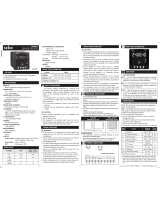
TERMINAL CONNECTION
TECHNICAL SPECIFICATION
Page-1
UTC-1202G Manual
TEMPERATURE CONTROLLER

Page-2
MECHANICAL INSTALLATION GUIDELINES
1. Prepare the panel cutout with proper dimensions as shown
above.
2. Fit the unit into the panel with the help of clamp given.
3. The equipment in its installed state must not come in close
proximity to any heating source, caustic vapors, oils steam,
or other unwanted process byproducts.
4. Use the specified size of crimp terminal (M3.5 screws) to
wire the terminal block. Tightening the screws on the
terminal block using the tightening torque of the range of
1.2 N.m.
5. Do not connect anything to unused terminals.
INSTALLATION GUIDELINES
1. This equipment, being built-in-type, normally becomes a
part of main control panel and in such case the terminals
do not remain accessible to the end user after installation
and internal wiring.
2. Do not allow pieces of metal, wire clippings, or fine metallic
fillings from installation to enter the product or else it may
lead to a safety hazard that may in turn endanger life or
cause electrical shock to the operator.
3. Circuit breaker or mains switch must be installed between
power source and supply terminal to facilitate power ‘ON’ or
‘OFF’ function. However this mains switch or circuit breaker
must be installed at convenient place normally accessible to
the operator.
4. Use and store the instrument within the specified ambient
temperature and humidity ranges as mentioned in this
manual.
MAINTENANCE
1. The equipment should be cleaned regularly to avoid
blockage of ventilating parts.
2. Clean the equipment with a clean soft cloth. Do not use
isopropyl alcohol or any other cleaning agent.
3. Fusible resistor must not be replaced by operator.
Read complete instructions prior to installation
and operation of the unit.
WARNING : Risk of electric shock.
SAFETY PRECAUTION
!
All safety related codifications, symbols and instructions
that appear in this operating manual or on the equipment
must be strictly followed to ensure the safety of the operating
personnel as well as the instrument.
If all the equipment is not handled in a manner specified
by the manufacturer, it might impair the protection provided
by the equipment.
WARNING GUIDELINES
WARNING : Risk of electric shock.
1. To prevent the risk of electric shock, power supply to the
equipment must be kept OFF while doing the wiring
arrangement. Do not touch the terminals while power is
being supplied.
2. To reduce electro magnetic interference, use wire with
adequate rating and twists of the same of equal size shall
be made with shortest connection.
3. Cable used for connection to power source, must have a
cross section of 1mm or greater. These wires should have
insulations capacity made of at least 1.5kV.
4. A better anti-noise effect can be expected by using
standard power supply cable for the instrument.
KEY OPERATION

PARAMETER SETTING
Page-3
Basic Parameter Setting :
Network, CT/PT Selection.
Advance Parameter Setting :
Load Hour %, No Load Hour, RPM.
Enter Password 25
Long Press key
To Enter into parameter
(5 to 50%)
(2 to 128)
Load Hour
Percentage
RPM
Enable / Disable
Pole
Press key to save & exit from
parameter setting
(10 to 500ms)
Pulse ON Time
Auto / Manual
Pulse Mode
(0.01, 0.1, 1, 10, 100, 1000)
Pulse Out
IF Auto
CT Primary
PT Primary
CT Secondary
(5 Amp to 6000 Amp
selectable)
(100V to 520kV selectable)
PT Secondary
(100V to 520V selectable)
Network Selection
(3P-4W/3P-3W/1P-2W)
(5 Amp/1 Amp selectable)
Press key to save & exit from
parameter setting
Enter Password 10
Long Press key
To Enter into parameter
PRG
PRG
PRG
PRG
PRG
PRG
PRG
Load Hour
Enable / Disable
PRG
PRG
PRG
PRG
PRG
PRG
PRG
PRG

Page-4

Page-5

Page-6
3P-3W 3P-4W
Display Line 1
Display Line 2
Display Line 3
Energy Value
L1 KW
L2 KW
L3 KW
3P-3W 3P-4W
Display Line 1
Display Line 2
Display Line 3
Energy Value
L1 KVA
L2 KVA
L3 KVA
1) kW PER PHASE
2) kVA PER PHASE
3P-3W 3P-4W
Display Line 1
Display Line 2
Display Line 3
Energy Value
L1 KVAr
L2 KVAr
L3 KVAr
3P-3W 3P-4W
Display Line 1
Display Line 2
Display Line 3
Energy Value
Total KW Total KW
Total KVA Total KVA
Total KVAR Total KVAR
3) kvar PER PHASE
4) Total kW,kVA,kvar
k
W
W hk
k V A
W hk
k v a r
W hk
k v a r
k
W
k V A
W hk
DISPLAY PAGES for Key
P
5) Max kW,kVA,kvar
k v a r
k
W
k V A
W hk
MAX
3P-3W 3P-4W
Display Line 1
Display Line 2
Display Line 3
Energy Value
Max KW Max KW
Max KVA Max KVA
Max KVAR Max KVAR
-
-
-
-
-
-
-
-
-

Page-7

Product improvement and upgrade is a constant procedure. So for more updated operating information and Support,
Please contact our Helpline: +91-9081078681/83 or Email at ser[email protected] Ver: 2306
Page-8
/