Page is loading ...

0.01
0.1
1
10
Ø User programmable CT primary and CT secondary.
Ø Memory retention.
Ø Potential free Pulse output for energy.
DISPLAY
6 digit 7 segment LED display, Height 0.5”
WIRING INPUT
3 Ø - 4 wire, 3 Ø - 3 wire, 2 Ø - 3 wire and
1 Ø - 2 wire system
RATED INPUT VOLTAGE
11 to 300V AC (L-N) ;
19 to 519V AC (L-L) Installation Category III
FREQUENCY RANGE
45-65 Hz
RATED INPUT CURRENT
Nominal 5A AC (Min-11mA, Max-6A)
CT PRIMARY
1A / 5A to 10,000A (Programmable for any Value)
Note : 1A to 10,000A if CT secondary is 1 else CT
primary is 5A to 10,000A
CT SECONDARY
1A or 5A (programmable)
BURDEN
0.5 VA@5A per phase
MEASUREMENT
kWh (resettable)
ACCURACY
Class 1
AUXILIARY SUPPLY RANGE
230V AC, ± 20%, 50 / 60Hz
OUTPUT
Pulse Output : Voltage range: External 24V DC max.
Current capacity : 100 mA max
Pulse Width : 100 ms ± 50 ms.
INT : 1000 pulses / kWh
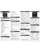
selec EM306A
Operating Instructions
FEATURES
SPECIFICATIONS
ENVIRONMENTAL CONDITIONS
- Indoor use
- Altitude of up to 2000 meters
- Pollution degree II
O
Temperature : Operating : -10 to 55 C
O
Storage : -20 to 75 C
Humidity : Up to 85% RH, non-condensing
MOUNTING
Panel mounting
WEIGHT
340gms
96 x 96
MECHANICAL INSTALLATION
Outline
Dimensions (in mm)
Panel cutout
Dimensions (in mm)
90.5
99
99
550 91.5
91.5
N
S2S1S2S1S2S1 V1
N
L
O
A
D
I1
V2 V3
L1
L2
L3
I2I3
PULSE O/P
L
N
+
CONNECTIONS DIAGRAM
TERMINAL CONNECTIONS
EM306A
FRONT PANEL DESCRIPTION
OP348-V01
EM306A
PRG
selec
INT
kWh
REV x10
1000
Impulse
/ kWh
CONFIGURATION
There are 4 dedicated keys with symbols marked as ,
, , . Use these 4 keys to enter into configuration
menu / change setting.
Note : The settings should be done by a professional,
after going through this users manual and after having
understood the application situation.
For the configuration setting mode :
! Use ( ) and ( ) keys for 3sec. to enter or exit from
configuration menu.
!Use ( ) and ( ) keys for increasing and decreasing
parameters value respectively.
!Use ( ) key to go back to previous page.
!Use ( ) key to save the setting and move on next page.
Function
Range or
Selection
Config
page.
Factory
Setting
Password
Change Password
New Password
Network Selection
CT Secondary
CT Primary
10
10
No
3P4W
1
1.1
2
3
45
5
0000 to 9998
No / Yes
3P3W / 3P4W
1A or 5A
1A, 5A to
10,000A (10.0kA)
0000 to 9998
For resetting energy parameters user will be prompted for
password. If correct password is entered, the user will be able to
reset all energy parameters. This password will be value which
will be greater than the configuration password by 1.
Factory Default
Reset Energy
Password
Reset Active Energy
5.02
5
5.1
5.01
11
No
No
No
No / Yes
No / Yes
0001 To 9999
No / Yes
<15
<150
<1500
≤ 2000
Pulse output
( kWh / pulse )
CT Ratio kWh
0.01
0.1
1
10
RESOLUTION :
SAFETY PRECAUTIONS
All safety related codifications, symbols and
instructions that appear in this operating manual or on
the equipment must be strictly followed to ensure the
safety of the operating personnel as well as the
instrument.
If the equipment is not used in a manner specified by the
manufacturer it might impair the protection provided by the
equipment.
Do not use the equipment if there is any mechanical
damage.
Ensure that the equipment is supplied with correct
voltage.
1. Read complete instructions prior to installation and
operation of the unit.
2. Risk of electric shock.
3. The equipment in its installed state must not come in close
proximity to any heating sources, steam, caustic vapors,
oils or other unwanted process by products.
1. This equipment, being built-in-type, normally becomes a
part of main control panel and in such case the terminals do
not remain accessible to the end user after installation and
internal wiring.
2. Conductors must not come in contact with the internal
circuitry of the equipment or else it may lead to a safety
hazard that may in turn endanger life or cause electrical
shock to the operator.
3. Circuit breaker or mains switch must be installed
between power source and supply terminals to facilitate
power ‘ON' or ‘OFF’ function. However this switch or
breaker must be installed in a convenient position normally
accessible to the operator.
4.
5. The equipment shall not be installed in environmental
conditions other than those mentioned in this manual.
. The equipment does not have a built-in-type fuse.
Installation of external fuse of rating 275V AC / Amp for
electrical circuitry is highly recommended.
Before disconnecting the secondary of the external current
transformer from the equipment, make sure that the current
transformer is short circuited to avoid risk of electrical
shock and injury.
6
0.5
/ battery
INSTALLATION GUIDELINES
1. To prevent the risk of electric shock, power supply to the
equipment must be kept OFF while doing the wiring
arrangement.
2. Wiring shall be done strictly according to the terminal
layout. Confirm that all connections are correct.
3. Use lugged terminals.
4. To reduce electromagnetic interference use of wires with
adequate ratings and twists of the same in equal size shall
be made with shortest connections.
5. Layout of connecting cables shall be away from any
internal EMI source.
6. Cable used for connection to power source, must have
2
a cross section of 1.5mm (AWG 15). These wires shall have
currentcarryingcapacity of 6A.
7. Before attempting work on device, ensure absence of
voltages using appropriate voltage detection device.
WIRING GUIDELINES
CAUTION :
WARNING :
CAUTION :
For installing the meter
1. Prepare the panel cutout with proper dimensions as shown
below.
2. Push the meter into the panel cutout. Secure the meter in
its place by fitting the clamp on the rear side. fit clamps on
both sides in diagonally opposite location for optimum
fitting.
3. For proper sealing, tighten the screws evenly with required
torque.
Terminal screw tightening torque : 0.5 N-m (4.42536 Lb-inch)
Screw clamp tightening torque : 0.1N-m (0.885 Lb-inch)
MAINTENANCE
1. The equipment should be cleaned regularly to avoid
blockage of ventilating parts.
2. Clean the equipment with a clean dry or damp cloth.
Do not use any cleaning agent other than water.
INT : The INT LED provides optical output for calibration
verification as well as visual indication of energy
integration. The pulse rate is 1000 Pulses/kWh.
X10 : X10 LED ON when the resolution is 10. It is the
indication of count reading which must be multiplied by
10 to get actual kWh consumed.
REV : REV LED gives the indication of reversal of two
or more CT connections or presence of negative power
in any or all phases. In such cases meter may not
indicate the correct energy consumption. The CT should
be connected to the meter with correct polarities.
USER GUIDE
LED INDICATIONS
Doc. name : OP INST EM306A OP348-V01(Page 1 of 2)

NETWORK SELECTION AND WIRING INPUT
Network selection in
configuration mode Wiring
3P4W
3P3W
3P4W, 2P3W, 1P2W
3P3W
TYPICAL WIRING DIAGRAM
3 PHASE 4 WIRE (Commonly Used) 2 PHASE - 3 WIRE
(Specifications subject to change as development is a continuous process.)
1 PHASE - 2 WIRE
Selec Controls Pvt. Ltd., India
Tel. No. : +91-22-28476443/1882
Fax No. : +91-22-28471733 I Toll free : 1800 227 353
Website: www.selec.com I Email: [email protected]
All fuse types : 0.5A class CC UL type ; 0.5A fast acting 600V
#
LOAD
LINE
L1
L2
L3
N
LOAD
LINE
L1
L2
N
LOAD
LINE
L1
N
S2S1 S2S1 S2S1 V1N V2 V3
I1I2I3
S2S1 S2S1 S2S1 V1N
PULSE
O/P
+
-
V2 V3
+
EM306A
I1I2I3
L
N
LN
#
#
PULSE
O/P
+
-
LOAD
LINE
L1
L2
L3
+
EM306A
L
N
LN
#
#
Doc. name : OP INST EM306A OP348-V01(Page 2 of 2)
3 PHASE - 3 WIRE
Pulse output from EM306A meter can be interfaced
into a process through a PLC for on line control of
energy content in the process.
If the PLC has a self excited digital input, external DC
supply is not needed.
The kWh pulse is also used to derive average kWh
information at the PLC.
Pulse output from EM306A meter can be used as
alarm generator or total energy controller by
interfacing it with Pre-settable counter and control
circuits (Contractors, Relay, Trip Circuit).
The counter is loaded with the maximum energy
consumption. When count reaches setpoint it
provides output to control circuit to take appropriate
action.
! PROCESS INTEGRATION
APPLICATION OF PULSE OUTPUT
! ENERGY CONTROLLER
I1
V1
V2
V3
VN
PULSE OUTPUT
CT
I2
I3
CT CT
12 / 24V DC
+
L
N
+
All fuse types : 0.5A class CC UL type
0.5A fast acting 600V
#
#
All fuse types : 0.5A class CC UL type
0.5A fast acting 600V
#
I1
V1
V2
V3
VN
PULSE OUTPUT
CT
I2
I3
CT CT
24V DC
maximum
+
L
N
+#
COUNTER
+
I / P
O / P To
Control
Circuit
P
L
C
S2S1 S2S1 S2S1 V1N
PULSE
O/P
+
V2 V3
+
EM306A
I1I2I3
L
N
LN
#
#
L
N
PULSE
O/P
+
LN
+
EM306A
#
#
S2S1 S2S1 S2S1 V1N V2 V3
I1I2I3
/