
© Freescale Semiconductor, Inc., 2006 - 2009. All rights reserved.
Freescale Semiconductor KTSPIGENHELPUG
User’s Guide Rev. 3.0, 10/2009
This document contains information on a new product.
Specifications and information herein are subject to change without notice.
SPIGen Help Instructions
SPIGen has additional HELP Instructions not provided in the software. This User’s Guide was created to provide the additional
help Instructions.
This SPIGen program has several new features that were added to support the new USB to SPI interface and the latest Freescale
evaluation board products that incorporate the USB to SPI feature.
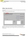
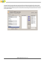
Once SPIGen is launched, the initial Window, shown above, called the “Not Configured” screen appears.
At this point, the SPIGen program is not connected to either the parallel port or the USB port of the user’s com-
puter.
The first step the user must take is to select the “Configure” menu item, shown above the Freescale logo in the
screen shot above.

SPIGen Help Instructions, Rev. 3.0
2 Freescale Semiconductor
The Edit Configuration Menu
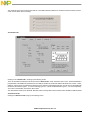
Clicking on the “Configure” menu item will cause an “Edit Configuration” drop down menu item to be displayed:
Clicking on the “Edit Configuration” menu item will bring up the General Tab of the “SPI Configuration” tabbed window, shown
below:
The major difference between this screen and that of SPIGen version 4.0.0, is the addition of the “Use USB instead of Parallel
Port” check box. When this box is checked, and stays checked, it indicates two things:
1) The SPIGen program is connected to the USB port for communication.
2) The USB port is active and a valid USB to SPI device is attached to the USB port.
If the check mark goes away, it indicates that a USB to SPI device is not attached or the software for this device is not properly
installed.
Another point to note is that, at this time, the USB to SPI interface only supports a maximum of 40 bits of data in the SPI word,
not 160, as is supported with the parallel interface. If there is sufficient demand for higher numbers of bits in the SPI word, future
generations of the SPIGen program will provide this.

SPIGen Help Instructions, Rev. 3.0
Freescale Semiconductor 3
The remainder of this document presumes that the “Use USB instead of Parallel Port” check box has been selected, and the
check mark is visible. (See next image)
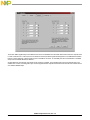
The SPI Pins Tab
Clicking on the “SPI Pins Tab” will bring up the following screen:
There are two differences between this screen and the “SPI Pins Tab” screen in SPIGen version 4.0.0. The SPI Baud Rate is
programmable in the USB to SPI interface due to the ability of the MCU to provide four different SPI baud rates., 4 MHz., 1 MHz.,
500 KHz., and 62.5 KHz. The radio buttons allow the user to select the preferred SPI baud rate. The SPI Type for the USB to SPI
interface is also limited to types 1, 2, 3 and 4. Selecting types 5, 6, 7,and 8 will default back to types 1, 2, 3 and 4 respectively.
This is due to the definition of the MCU’s SPI module.
The other features of this screen, Bit Order, Data Out, Data In and Chip Select are the same for either th USB or Parallel interface.
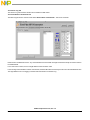
The Extra Pins Tab
Clicking the “Extra Pins Tab” brings up the following screen:

SPIGen Help Instructions, Rev. 3.0
4 Freescale Semiconductor
This screen differs significantly from the Extra Pins screen in the Parallel Port mode. While there are the same nine outputs, Data
0 - Data 4 and Control 0 - Control 3, there is no selection of which pins these signals are assigned to. In the USB to SPI hardware,
there is a jumper mapping of these signals to pins on the DB-25 connector, so essentially the same customization is available
except it is in hardware rather than software.
Another difference is that these nine signals are all “present” by default. In the parallel mode case, these signals have to be
enabled one at a time, and assigned to pins. All nine signals are MCU outputs and therefore their drive fan out is limited to that
of a standard CMOS output.

SPIGen Help Instructions, Rev. 3.0
Freescale Semiconductor 5
The Session Log Tab
The Session Log Tab should be identical for the Parallel or USB modes.
The Send a Batch of Commands Tab
The Main Program Screen contains a tab called “Send a Batch of Commands”. This screen should be
Identical to the Parallel Mode screen. Any command batches that send SPI messages should work exactly the same as those in
the Parallel Mode.
In the next screen however, there is a slight difference that should be noted.
In the sending of the Extra Bits in a batch command file, the Extra Bits will be sent exactly the same as in the Parallel Mode case.
The slight difference is in the logging of the Extra Bit commands in the Session Log.

SPIGen Help Instructions, Rev. 3.0
6 Freescale Semiconductor
As can be seen from the screen capture on the next page, the batch commands sent are all Data 0 and Control 0 extra bit
commands, yet the log indicates SPI messages being sent and received. These SPI message in the log should be ignored
because, in fact no SPI messages were sent, just extra bit messages. The fact that the USB interface always sends and receives
8 bytes is interpretted by the SPIGen program as an issued and received SPI message. If time permits, this will be coreected in
the next release of SPIGen.

How to Reach Us:
Home Page:
www.freescale.com
Web Support:
http://www.freescale.com/support
USA/Europe or Locations Not Listed:
Freescale Semiconductor, Inc.
Technical Information Center, EL516
2100 East Elliot Road
Tempe, Arizona 85284
1-800-521-6274 or +1-480-768-2130
www.freescale.com/support
Europe, Middle East, and Africa:
Freescale Halbleiter Deutschland GmbH
Technical Information Center
Schatzbogen 7
81829 Muenchen, Germany
+44 1296 380 456 (English)
+46 8 52200080 (English)
+49 89 92103 559 (German)
+33 1 69 35 48 48 (French)
www.freescale.com/support
Japan:
Freescale Semiconductor Japan Ltd.
Headquarters
ARCO Tower 15F
1-8-1, Shimo-Meguro, Meguro-ku,
Tokyo 153-0064
Japan
0120 191014 or +81 3 5437 9125
Asia/Pacific:
Freescale Semiconductor China Ltd.
Exchange Building 23F
No. 118 Jianguo Road
Chaoyang District
Beijing 100022
China
+86 10 5879 8000
For Literature Requests Only:
Freescale Semiconductor Literature Distribution Center
P.O. Box 5405
Denver, Colorado 80217
1-800-441-2447 or +1-303-675-2140
Fax: +1-303-675-2150
Freescale™ and the Freescale logo are trademarks of
Freescale Semiconductor, Inc. All other product or service names
are the property of their respective owners.
© Freescale Semiconductor, Inc.2006 - 2009. All rights reserved.
KTSPIGENHELPUG
Rev. 3.0
10/2009
Information in this document is provided solely to enable system and
software implementers to use Freescale Semiconductor products. There are
no express or implied copyright licenses granted hereunder to design or
fabricate any integrated circuits or integrated circuits based on the
information in this document.
Freescale Semiconductor reserves the right to make changes without further
notice to any products herein. Freescale Semiconductor makes no warranty,
representation or guarantee regarding the suitability of its products for any
particular purpose, nor does Freescale Semiconductor assume any liability
arising out of the application or use of any product or circuit, and specifically
disclaims any and all liability, including without limitation consequential or
incidental damages. “Typical” parameters that may be provided in Freescale
Semiconductor data sheets and/or specifications can and do vary in different
applications and actual performance may vary over time. All operating
parameters, including “Typicals”, must be validated for each customer
application by customer’s technical experts. Freescale Semiconductor does
not convey any license under its patent rights nor the rights of others.
Freescale Semiconductor products are not designed, intended, or authorized
for use as components in systems intended for surgical implant into the body,
or other applications intended to support or sustain life, or for any other
application in which the failure of the Freescale Semiconductor product could
create a situation where personal injury or death may occur. Should Buyer
purchase or use Freescale Semiconductor products for any such unintended
or unauthorized application, Buyer shall indemnify and hold Freescale
Semiconductor and its officers, employees, subsidiaries, affiliates, and
distributors harmless against all claims, costs, damages, and expenses, and
reasonable attorney fees arising out of, directly or indirectly, any claim of
personal injury or death associated with such unintended or unauthorized
use, even if such claim alleges that Freescale Semiconductor was negligent
regarding the design or manufacture of the part.
-
 1
1
-
 2
2
-
 3
3
-
 4
4
-
 5
5
-
 6
6
-
 7
7


NXP MC33937 User guide
- Type
- User guide
Ask a question and I''ll find the answer in the document
Finding information in a document is now easier with AI
Related papers
Other documents
-
Freescale Semiconductor KIT33932VWEVBE User manual
-
-
-
-
-
 Spigen SGP11612 Product information
-
 Spigen PF2101 ArcField Wireless Charger User manual
-
-
-

