Page is loading ...

Freescale Semiconductor, Inc.
User’s Guide
© Freescale Semiconductor, Inc., 2015. All rights reserved.
Document Number: KT34FS6407-34FS6408UG
Rev. 1.0, 8/2015
KIT34FS6407EVB and KIT34FS6408EVB
Evaluation Board
Figure 1. KIT34FS6407EVB and KIT34FS6408EVB Board

KT34FS6407-34FS6408UG User’s Guide Rev. 1.0 8/2015
2 Freescale Semiconductor, Inc.
Contents
1 Important Notice. . . . . . . . . . . . . . . . . . . . . . . . . . . . . . . . . . . . . . . . . . . . . . . . . . . . . . . . . . . . . . . . . . . . . . . . . . . . . . . .3
2 Getting Started. . . . . . . . . . . . . . . . . . . . . . . . . . . . . . . . . . . . . . . . . . . . . . . . . . . . . . . . . . . . . . . . . . . . . . . . . . . . . . . . .4
3 Terms. . . . . . . . . . . . . . . . . . . . . . . . . . . . . . . . . . . . . . . . . . . . . . . . . . . . . . . . . . . . . . . . . . . . . . . . . . . . . . . . . . . . . . . .5
4 Getting to Know the Hardware. . . . . . . . . . . . . . . . . . . . . . . . . . . . . . . . . . . . . . . . . . . . . . . . . . . . . . . . . . . . . . . . . . . . .6
5 Accessory Interface Board . . . . . . . . . . . . . . . . . . . . . . . . . . . . . . . . . . . . . . . . . . . . . . . . . . . . . . . . . . . . . . . . . . . . . . .21
6 Installing the Software and Setting up the Hardware. . . . . . . . . . . . . . . . . . . . . . . . . . . . . . . . . . . . . . . . . . . . . . . . . . .23
7 Initialization and Configuration Mode. . . . . . . . . . . . . . . . . . . . . . . . . . . . . . . . . . . . . . . . . . . . . . . . . . . . . . . . . . . . . . .30
8 Schematic . . . . . . . . . . . . . . . . . . . . . . . . . . . . . . . . . . . . . . . . . . . . . . . . . . . . . . . . . . . . . . . . . . . . . . . . . . . . . . . . . . .31
9 Board Layout . . . . . . . . . . . . . . . . . . . . . . . . . . . . . . . . . . . . . . . . . . . . . . . . . . . . . . . . . . . . . . . . . . . . . . . . . . . . . . . . .32
10 References. . . . . . . . . . . . . . . . . . . . . . . . . . . . . . . . . . . . . . . . . . . . . . . . . . . . . . . . . . . . . . . . . . . . . . . . . . . . . . . . . . .37
11 Revision History . . . . . . . . . . . . . . . . . . . . . . . . . . . . . . . . . . . . . . . . . . . . . . . . . . . . . . . . . . . . . . . . . . . . . . . . . . . . . . .38

Important Notice
KT34FS6407-34FS6408UG User’s Guide Rev. 1.0 8/2015
Freescale Semiconductor, Inc. 3
1 Important Notice
Freescale provides the enclosed product(s) under the following conditions:
This evaluation kit is intended for use of ENGINEERING DEVELOPMENT OR EVALUATION PURPOSES
ONLY. It is provided as a sample IC pre-soldered to a printed circuit board to make it easier to access inputs,
outputs, and supply terminals. This evaluation kit may be used with any development system or other source
of I/O signals by simply connecting it to the host MCU or computer board via off-the-shelf cables. Final device
in an application will be heavily dependent on proper printed circuit board layout and heat sinking design as
well as attention to supply filtering, transient suppression, and I/O signal quality.
The goods provided may not be complete in terms of required design, marketing, and or manufacturing related
protective considerations, including product safety measures typically found in the end product incorporating
the goods. Due to the open construction of the product, it is the user's responsibility to take any and all
appropriate precautions with regard to electrostatic discharge. In order to minimize risks associated with the
customers applications, adequate design and operating safeguards must be provided by the customer to
minimize inherent or procedural hazards. For any safety concerns, contact Freescale sales and technical
support services.
Should this evaluation kit not meet the specifications indicated in the kit, it may be returned within 30 days from
the date of delivery and will be replaced by a new kit.
Freescale reserves the right to make changes without further notice to any products herein. Freescale makes
no warranty, representation or guarantee regarding the suitability of its products for any particular purpose, nor
does Freescale assume any liability arising out of the application or use of any product or circuit, and
specifically disclaims any and all liability, including without limitation consequential or incidental damages.
“Typical” parameters can and do vary in different applications and actual performance may vary over time. All
operating parameters, including “Typical”, must be validated for each customer application by customer’s
technical experts.
Freescale does not convey any license under its patent rights nor the rights of others. Freescale products are
not designed, intended, or authorized for use as components in systems intended for surgical implant into the
body, or other applications intended to support or sustain life, or for any other application in which the failure
of the Freescale product could create a situation where personal injury or death may occur.
Should the Buyer purchase or use Freescale products for any such unintended or unauthorized application,
the Buyer shall indemnify and hold Freescale and its officers, employees, subsidiaries, affiliates, and
distributors harmless against all claims, costs, damages, and expenses, and reasonable attorney fees arising
out of, directly or indirectly, any claim of personal injury or death associated with such unintended or
unauthorized use, even if such claim alleges that Freescale was negligent regarding the design or manufacture
of the part. Freescale™ and the Freescale logo are trademarks of Freescale Semiconductor, Inc. All other
product or service names are the property of their respective owners. © Freescale Semiconductor, Inc. 2015

Getting Started
KT34FS6407-34FS6408UG User’s Guide Rev. 1.0 8/2015
4 Freescale Semiconductor, Inc.
2 Getting Started
2.1 Kit Contents/Packing List
The KIT34FS6407EVB and KIT34FS6408EVB contents include:
• Assembled and tested evaluation board/module in anti-static bag
• Warranty card
2.2 Jump Start
Freescale’s analog product development boards help to easily evaluate Freescale products. These tools support analog mixed signal and
power solutions including monolithic ICs using proven high-volume SMARTMOS mixed signal technology, and system-in-package devices
utilizing power, SMARTMOS and MCU dies. Freescale products enable longer battery life, smaller form factor, component count reduction,
ease of design, lower system cost and improved performance in powering state of the art systems.
• Click on the appropriate link for your board
KIT34FS6407EVB: www.freescale.com/KIT34FS6407EVB
KIT34FS6408EVB: www.freescale.com/KIT34FS6408EVB
• Review your Tool Summary Page
• Look for
• Download documents, software, and other information
Once the files are downloaded, review the user guide in the bundle. Jump start bundles are available on each tool summary page with the
most relevant and current information. The information includes everything needed for design.
2.3 Required Equipment and Software
To use this kit, you need
•2.7 V to 40 V power supply, 3.0 A capability
• Freescale’s KITUSBSPIDGLVME interface dongle
• SPIGen Graphical User Interface or MC3390X_GUI
When not connected to an evaluation board, the KITUSBSPIDGLVME can be used in standalone mode to program its
onboard MC68HC908JW32 microcontroller. In this case, the interface dongle and USB cable are required. For more
information, see the “
SPIGen 7 User Guide”.
2.4 System Requirements
The kit requires the following:
• USB-enabled PC with Windows
®
XP or higher
Jump Start Your Design

Terms
KT34FS6407-34FS6408UG User’s Guide Rev. 1.0 8/2015
Freescale Semiconductor, Inc. 5
3Terms
Part Number or
Parameter
Definition
CAN_5V 5.0 V CAN voltage
EVB Evaluation Board
FCCU Fault Collection and Control Unit
FS0B Fail-safe Output Number 0
INTB Interrupt
IO Input/Output
LDO Low-dropout Regulator
RSTB Reset
SMPS Switching Mode Power Supply
SPIGen Software utility (installed on a PC) provides communication functions between the PC and a Freescale evaluation board
V
AUX
Auxiliary power supply
V
CCA
Power supply for ADC
V
PRE
Pre-regulator voltage
WD Watchdog

Getting to Know the Hardware
KT34FS6407-34FS6408UG User’s Guide Rev. 1.0 8/2015
6 Freescale Semiconductor, Inc.
4 Getting to Know the Hardware
4.1 Board Overview
KIT34FS6407EVB and KIT34FS6408EVB evaluation boards demonstrate the functionality of the SMARTMOS MC34FS6407 and
MC34FS6408 power system basis chips, respectively. These ICs are equipped with an intelligent power management system including
safety features targeting the latest ISO26262 automotive functional safety standard. The EVB is a standalone board that can be used
either with a compatible microcontroller or with a PC. The latter case requires a KITUSBSPIDGLEVME accessory interface board. See
Section 2.3 "Required Equipment and Software".
4.2 Board Features
This EVB comes mounted with either an MC34FS6407 or an MC34FS6408 IC. The main features of the board are:
•V
BAT
power supply either through power jack (2.0 mm) or phoenix connector
•V
CORE
configuration:1.2 V or 3.3 V
•V
CCA
configuration: 5.0 V/3.3 V
• Internal transistor or external PNP
•V
AUX
configuration: 3.3 V or 5.0 V
• Enabled or disabled at startup
• Ignition key switch
• CAN bus
• IO connector (IO_0 to IO_5)
• Debug connector (SPI bus, CAN digital, RSTB, FS0B, INTB, Debug, MUX_OUT)
• Signalling LED to give state of signals or regulators
4.3 Device Features
The MC34FS6407 and the MC34FS6408 are multi-output ICs, with power supply and HSCAN transceiver. The MC34FS6407 is designed
to support up 800 mA on V
CORE
, while MC34FS6408 supports up to 1.5 A on V
CORE
. All other features are the same.
Table 1. Device Features
Device Description Features
MC34FS6407/
MC34FS6408
Power system
basis chip with
high-speed CAN
and LIN
transceivers
• Highly flexible SMPS pre-regulator, allowing two topologies: non-inverting buck-boost or
standard buck
• Switching mode power supply (SMPS) dedicated to MCU core supply: 1.2 V or 3.3 V,
delivering up to 1.5 A for the MC34FS6408 and up to 800 mA for the MC34FS6407
• Linear voltage regulator dedicated to MCU A/D reference voltage or I/Os supply (VCCA):
5.0 V or 3.3 V
• Linear voltage regulator dedicated to auxiliary functions or to a sensor supply (VCCA
tracker or independent 5.0 V/3.3 V)
• Multiple wake-up sources in Low-power mode: CAN and/or IOs
• Battery voltage sensing and multiplexer output terminal (various signal monitoring)
• Enhanced safety block associated with fail-safe outputs
• Six configurable I/Os
• ISO11898 high-speed CAN interface compatibility for baud rates of 40 kB/s to 1.0 MB/s
• High EMC immunity and ESD robustness

Getting to Know the Hardware
KT34FS6407-34FS6408UG User’s Guide Rev. 1.0 8/2015
Freescale Semiconductor, Inc. 7
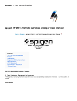
4.4 Board Description
The EVB comes with either a Freescale MC34FS6407or MC34FS6408 IC mounted on it. Below is a view of the board indicating the major
components.
Figure 2. Board Description —MC34FS6407and MC34FS6408
Table 2. Board Description
Name Description
Buck/Buck-Boost Section
•V
PRE
DC/DC selection mode, either Boost or Buck
Battery Connection
• Battery voltage input, either on Jack (black connector) or Phoenix (green) connector
Main Switch
• Battery voltage ON/OFF
Power Supplies
Buck/Buck Boost
Section
LEDs for
Power
Supplies
Compensation
Network
V
CORE
Selection
DBG Mode
Select
SPI Dongle
Connector
Battery
Connection
Main
Switch
Ignition
Key
Switch
LIN Bus
(Not Avaiable on
KIT34FS640xEVB)
CAN Bus
FS Output
Circuitry
V
CCA
and V
AUX
Selection
Main Signals of
MC34FS6407/MC34FS6406
Second Resistor Bridge
- V
DRIFG
Selection
I/Os of
MC34FS6407/MC34FS6406

Getting to Know the Hardware
KT34FS6407-34FS6408UG User’s Guide Rev. 1.0 8/2015
8 Freescale Semiconductor, Inc.
4.5 Evaluation Board Configuration
Figure 3 shows a configuration example for the EVB, which enables:
•V
CORE
3.3 V
• Compensation network for MPC5643L
•V
CCA
and V
AUX
= 5.0 V
•V
CCA
with external PNP
• Debug mode
•V
PRE
in Buck mode
•V
DDIO
tied to V
CCA
• Various signalling LEDs enabled
• IO1 configured as IN/OUT
Ignition Key Switch
• Simulate ignition key. Connected to IO_0
LIN Bus
• LIN bus as a master (Not available on KIT34FS640xEVB)
CAN Bus
• CANH and CANL differential pair
I/Os of MC34FS6407_8
• All IOs, VDDIO and GND available
Second Resistor Bridge - V
DRIFT
Selection
• Bridge resistor for V
CORE
redundant check
Main Signals of MC34FS6407_8
• SPI, VDDIO, fail-safe pin, CAN, MUXOUT, INTB and RSTB available
V
CCA
and V
AUX
Selection
•V
CCA
and V
AUX
voltage selection
FS Output Circuitry
• FS0B configuration
SPI Dongle Connector
• Connector with SPI bus. Compliant to SPIGen Freescale board
DBG Mode Select
• Controls Debug or Normal mode entering at boot up
V
CORE
Selection
•V
CORE
voltage selection
Compensation Network
• Compensation network selection
LEDs for Power Supplies
• Switches for ON/OFF on LEDs
Power Supplies
• MC34FS6407 or MC34FS6408 output power supply (V
PRE
, V
CORE
, V
AUX
, V
CCA
)
Table 2. Board Description (continued)
Name Description

Getting to Know the Hardware
KT34FS6407-34FS6408UG User’s Guide Rev. 1.0 8/2015
Freescale Semiconductor, Inc. 9
Figure 3. Default Board Configuration
KIT34FS640XEVB REV A
2015 FREESCALE
Switch Jumper Red LED Green LED

Getting to Know the Hardware
KT34FS6407-34FS6408UG User’s Guide Rev. 1.0 8/2015
10 Freescale Semiconductor, Inc.
4.6 LED Definitions
The following table lists the LEDs used as visual output devices on the EVB:
4.7 Test Point Definitions
The following test-point jumpers provide access to signals on the MC34FS6407or MC34FS6408:
Table 3. LEDs
Schematic
Label
Name Description
D6 V
PRE
Indicator of pre-regulator voltage
D7 V
AUX
Indicator of auxiliary power supply
D8 V
CCA
Indicator of ADC power supply
D9 CAN_5V Indicator of 5.0 V CAN voltage
D10 IO_5 Indicator of IO_5 state
D11 IO_4 Indicator of IO_4 state
D12 FS0B Indicator for fail-safe output number 0
D13 V
BAT_P
Indicator of battery voltage after protection diode
D14 RSTB Indicator of a reset
D15 INTB Indicator of an interrupt
D17 V
CORE
Indicator of V
CORE
power supply
Table 4. Test Points
Schematic Label Signal Name Description
TP2 J24.3 -
TP3 J24.5 -
TP4 J24.7 -
TP5 J20.16 -
TP6 PGND Power ground
TP7 PGND Power ground
TP8 GND Ground
TP9 GND Ground
TP10 GND Ground
TP11 GND Ground
TP12 GND Ground
TP13 GND Ground
TP14 GND Ground
TP15 GND Ground

Getting to Know the Hardware
KT34FS6407-34FS6408UG User’s Guide Rev. 1.0 8/2015
Freescale Semiconductor, Inc. 11
TP16 GND Ground
TP17 GND Ground
TP18 J24.2 -
TP19 J24.4 -
TP20 J24.6 -
TP21 J24.8 -
TP22 J24.10 -
TP23 J24.12 -
TP24 J24.14 -
TP25 J24.16 -
TP26 V
PRE
Pre-regulator voltage
TP27 V
CORE
Core voltage for the MCU
TP28 CANH -
TP29 CANL -
TP30 LIN LIN bus (Not available on
KIT34FS640xEVB)
TP31 MUX_OUT Output from the analog multiplexer
TP32 FS0B Fail-safe output
TP33 RSTB Reset signal
TP34 INTB Interrupt output
TP35 V
SW
V
PRE
Switching voltage
TP36 V
AUX
Auxiliary power supply
TP37 V
CCA
ADC power supply
TP38 CAN_5V CAN power supply
TP39 V
SUP3
Supply voltage
TP40 VSW_Core V
CORE
supply voltage
Table 4. Test Points (continued)
Schematic Label Signal Name Description

Getting to Know the Hardware
KT34FS6407-34FS6408UG User’s Guide Rev. 1.0 8/2015
12 Freescale Semiconductor, Inc.
4.8 Connector and Jumper Definitions
Table 5. Main Power Supply Connector
JP1 Pin Number Name of Power Rail Description
1V
CORE
Core voltage for the MCU
2 PGND Power ground
3V
CCA
ADC power supply
4 GND Ground
5V
AUX
Auxiliary power supply
6 GND Ground
7 CAN_5V CAN power supply
8 GND Ground
9V
PRE
Pre-regulator voltage
10 PGND Power ground
Table 6. Jumpers J1 through J31 (Including Connectors)
Schematic
Label
Pin Number Pin Name Jumper/Pin Function
J1
Compensation network for FB_core – part 1
1-2 V
CORE
= 1.23 V
3-4 V
CORE
= 3.3 V
J2
C_OUT – selection of output capacitance for V
CORE
If connected, output capacitance is 40 µF, 20 µF otherwise
No jumper C
OUT
= 20 µF
1-2 C
OUT
= 40 µF
J3
Power supply DC 12 V
J4
Buck-boost/standard buck mode configuration
1-2
Buck-boost configuration
3-4
No jumper
Buck only configuration
J5
V
CORE
selection
1-2
V
CORE
= 1.23 V
3-4
V
CORE
= 3.3 V

Getting to Know the Hardware
KT34FS6407-34FS6408UG User’s Guide Rev. 1.0 8/2015
Freescale Semiconductor, Inc. 13
J6
Configuration for Boots_core pin
1-2
Boots_core pin connected to GND – used for devices with linear voltage regulator on
V
CORE
2-3
Boots_core pin connected to SW_core – used for devices with switching mode power
supply on V
CORE
J7
Power supply (max. voltage = 40 V)
This connector should be used to supply EVB from protected voltage source
1 VBAT
Positive supply
2GND
Ground
J8
Power supply for EVB
Allows disconnecting of all three supply pins for current measurements
Normally (no measurement), jumpers should be connected
1-2
Enables power supply (V
BAT_P
) for VSUP3 pin of MC34FS6407(or MC34FS6408)
3-4
Enables power supply (V
SUP
) for VSUP1 and VSUP2 pins of MC34FS6407(or
MC34FS6408)
J9
Compensation network for FB_core – part 2
1-2
V
CORE
= 1.23 V
3-4
V
CORE
= 3.3 V
J10
V
SNS
_EN – connects battery voltage before filter to V
SENSE
J11
External transistor for V
CCA
1-2
Emitter of Q2 connected to VCCA_E
2-3
External transistor Q2 is not used
J12
IO_0_PD – pulls down IO_0
J13
FS0B pull-up connection
1-2
FS0B pull-up is supplied from V
SUP3
2-3
FS0B pull-up is supplied from V
DDIO
J14
Connects base of the transistor Q2 to the VCCA_B pin
J15
External resistor bridge monitoring (for future use)
Used in conjunction with J18
Resistor bridge has to be in same configuration as J5
Voltage on this voltage divider has to be adjusted to same level as for first bridge using potentiometer R17
1-2
V
CORE
= 1.23 V
3-4
V
CORE
= 3.3 V
Table 6. Jumpers J1 through J31 (Including Connectors) (continued)
Schematic
Label
Pin Number Pin Name Jumper/Pin Function

Getting to Know the Hardware
KT34FS6407-34FS6408UG User’s Guide Rev. 1.0 8/2015
14 Freescale Semiconductor, Inc.
J16
V
DDIO
tracking
1-2
V
DDIO
tracks V
CCA
2-3
V
DDIO
tracks V
CORE
J17
DBG_EN - enables debug mode
No jumper
Normal mode
1-2
Debug mode
J18
DRIFT_MONIT – External resistor bridge monitoring
1-2
Second resistor bridge on IO_1 is disabled
2-3
Reserved for future use
J19
V
CCA
/V
AUX
regulator selection
1-3 and 2-4
V
AUX
is disabled
3-5 and 4-6
V
AUX
is enabled
Table 6. Jumpers J1 through J31 (Including Connectors) (continued)
Schematic
Label
Pin Number Pin Name Jumper/Pin Function

Getting to Know the Hardware
KT34FS6407-34FS6408UG User’s Guide Rev. 1.0 8/2015
Freescale Semiconductor, Inc. 15
J20
Additional Inputs/Output
1FS0B
Fail-safe output
2 VDDIO
V
DDIO
voltage
3MISO
SPI – Master Input Slave Output
4RSTB
Reset pin – connect to the reset line of the MCU
5MOSI
SPI – Master Output Slave Input
6GND
Ground
7SCLK
SPI – clock
8GND
Ground
9NCS
SPI – Chip Select
10 GND
Ground
11 MUX_OUT
Output from the multiplexer – connect to the MCU's ADC
12 INTB
Interrupt pin – connect to the MCU IO with an interrupt capability
13 RXD_L
LIN receive pin – connect to the MCU — Not Available on KIT34FS640xEVB
14 TXD_L
LIN transmit pin – connect to the MCU — Not Available on KIT34FS640xEVB
15 GND
Ground
16 TP5
-
17 RXD
CAN receive pin – connect to the MCU
18 TXD
CAN transmit pin – connect to the MCU
19 DBG
Debug pin
20 GND
Ground
J21
LIN connector
1LIN
LIN after transceiver (NOT the MCU side) — Not Available on KIT34FS640xEVB
2GND
Ground
J22
CAN connector
1CANH
CANH signal after transceiver (NOT the MCU side)
2CANL
CANL signal after transceiver (NOT the MCU side)
Table 6. Jumpers J1 through J31 (Including Connectors) (continued)
Schematic
Label
Pin Number Pin Name Jumper/Pin Function

Getting to Know the Hardware
KT34FS6407-34FS6408UG User’s Guide Rev. 1.0 8/2015
16 Freescale Semiconductor, Inc.
J23
General Inputs/Outputs
pin1 IO_1
-
pin2 IO_0
-
pin3 IO_3
-
pin4 IO_2
-
pin5 IO_5
-
pin6 IO_4
-
pin7 VDDIO
-
pin8 NC
-
pin9 VBAT
-
pin10 GND
-
J24
SPI/USB dongle or MCU connection
SPI/USB dongle should be directly connected to this port
pin1 GND
Ground
pin2 TP18
-
pin3 TP2
-
pin4 TP19
-
pin5 TP3
-
pin6 TP20
-
pin7 TP4
-
pin8 TP21
-
pin9 SCLK
SPI – clock
pin10 TP22
Not connected
pin11 MOSI
SPI – Master Output Slave Input
pin12 TP23
-
pin13 MISO
SPI – Master Input Slave Output
pin14 TP24
-
pin15 NCS
SPI – Chip Select
pin16 TP25
-
J25
Power supply for LEDs on IO_4 and IO_5 (D11, D10)
1-2
Enables power supply for IO_4 (D11)
3-4
Enables power supply for IO_5 (D10)
J26
RSTB_LED_EN – enables LED D14 for RSTB output
Table 6. Jumpers J1 through J31 (Including Connectors) (continued)
Schematic
Label
Pin Number Pin Name Jumper/Pin Function

Getting to Know the Hardware
KT34FS6407-34FS6408UG User’s Guide Rev. 1.0 8/2015
Freescale Semiconductor, Inc. 17
J27
INTB_LED_EN – enables LED D15 for INTB output
J28
IO5_OUT – IO_5 output configuration
1-2
IO_5 connected to LED D10 via transistor Q5
2-3
IO_5 pulled down
J29
IO4_OUT – IO_4 output configuration
1-2
IO_4 pulled down
2-3
IO_4 connected to LED D11 via transistor Q6
J30
Enable LED D12 for fail-safe.
J31
Enables LED D13 as indicator of power supply
J32
Enables LED D17 as indicator for V
CORE
power supply
Table 6. Jumpers J1 through J31 (Including Connectors) (continued)
Schematic
Label
Pin Number Pin Name Jumper/Pin Function

Getting to Know the Hardware
KT34FS6407-34FS6408UG User’s Guide Rev. 1.0 8/2015
18 Freescale Semiconductor, Inc.
4.8.1 Compensation Network
A voltage regulator needs feedback from the V
CORE
voltage to be able to adjust (control) output voltage. For this reason, two bridges are
implemented in the external MC34FS6407 or MC34FS6408 circuitry. Static feedback (steady-state) voltage is defined by a simple resistor
bridge (given by RA3/RB3 and RA4). Dynamic behavior of the regulator is controlled by another bridge that is an RC divider (defined by
RBx, CBx, R1, C1, R2, C2).
Figure 4 shows the compensation network. Steady-state voltage can be either 1.2 V or 3.3 V. To tune the
dynamic performance, the board is equipped with two different bridges (possible combinations of the jumpers J1 and J9 are shown in
Table 7). The combinations shown in Table 7 are chosen to provide optimal performance for the given output voltage. The real dynamic
performance can differ for different applications and can be tuned by changing the compensation network and by adding output capacitors
(J2).
Figure 4. Compensation Network and V
CORE
Setup Schematic
Table 7. Compensation Network and V
CORE
Settings
V
CORE
(V)
Jumper Settings
Static Behavior Dynamic Behavior
J5 J1 J9
1.23 3-4 3-4 3-4
3.3 1-2 1-2 1-2
V
CORE
V
CORE
_sense

Getting to Know the Hardware
KT34FS6407-34FS6408UG User’s Guide Rev. 1.0 8/2015
Freescale Semiconductor, Inc. 19
4.8.2 Second Resistor Bridge - V
DRIFT
Monitoring
To increase the safety level of an application, a second resistor bridge has been added. This bridge generates the same voltage as the
bridge connected to FB_core pin. If the difference between voltages is greater than V
DRIFT
, the FS state machine is impacted.
Invoking this functionality involves both the board hardware and the software configuration. On the hardware side, the second resistor
bridge must be configured by jumper J18, as shown in the Figure 5, and adjusted by the potentiometer R17 to set the same voltage as on
the first bridge. Software sets registers INIT_Vreg1 (bit Vcore_FB to 1) and register INIT_FSSM1 (bit IO_1_FS to 1).
Figure 5. Second Resistor Bridge
Table 8. V
DRIFT
Monitoring Settings
V
CORE
(V)
Hardware Settings
J15 J18
1.23 1+2 3+4
3.3 3+4 1+2
V
CORE
V
CORE
V
CORE
J15
IO _ 1 V
CORE
FB Drift Enable

Getting to Know the Hardware
KT34FS6407-34FS6408UG User’s Guide Rev. 1.0 8/2015
20 Freescale Semiconductor, Inc.
4.9 Switch Definitions
Table 9. Switches
Switch Number Position Function Description
SW1
Power supply select
1-2
Supply from J7 selected
2-3
Power jack on J3 selected
SW2
V
CCA
/V
AUX
switch
Only one choice is possible at the same time
1
3.3 V / 3.3 V
2
5.0 V / 5.0 V
3
3.3 V / 5.0 V This setting is not allowed if V
AUX
is not used - option
V
CCA
only (selected by J19)
4
5.0 V / 3.3 V
SW3
LEDs - indicators for power supplies
1
V
PRE
Enables LED indicator for pre-regulator
2
V
AUX
Enables LED indicator for auxiliary power supply
3
V
CCA
Enables LED indicator for V
CCA
regulator
4
CAN_5 V Enables LED indicator for CAN regulator
SW4
Ignition switch
1-2
IO_0 connected to V
BAT
(ignition key active)
2-3
No voltage on the IO_0
/