6
Instrument selection
Radar
58365-US-191014
3 Instrument selection
Application area
The radar sensors of the VEGAPULS 10, 20, 30 series described here are
used for non-contact level measurement of liquids and bulk solids. They can
be used in both simple and aggressive liquids. The sensors also measure
light and heavy bulk solids absolutely reliably, both with strong dust and
noise generation and independent of buildup or condensation.
Device overview
VEGAPULS C 11
VEGAPULS C 11 is the ideal sensor for non-contact level measurement in
simple applications where a high degree of protection is required. It is par-
ticularly suitable for use in water treatment, pumping stations, rain overow
basins and level monitoring.
VEGAPULS C 21, C 22, C 23
VEGAPULS C 21, C 22, C 23 are the ideal sensors for non-contact level
measurement in simple applications where a high degree of protection is
required. They are particularly suitable for use in water treatment, pumping
stations and rain overow basins, for ow measurement in open channels
and level monitoring.
VEGAPULS 11, 21, 31
VEGAPULS 11, 21, 31 are the ideal sensors for non-contact level mea-
surement in simple applications. They are particularly suitable for use in
water treatment, storage tanks with acids, lyes and additives in all industrial
areas, or for measuring levels in plastic tanks from the outside through the
tank wall.
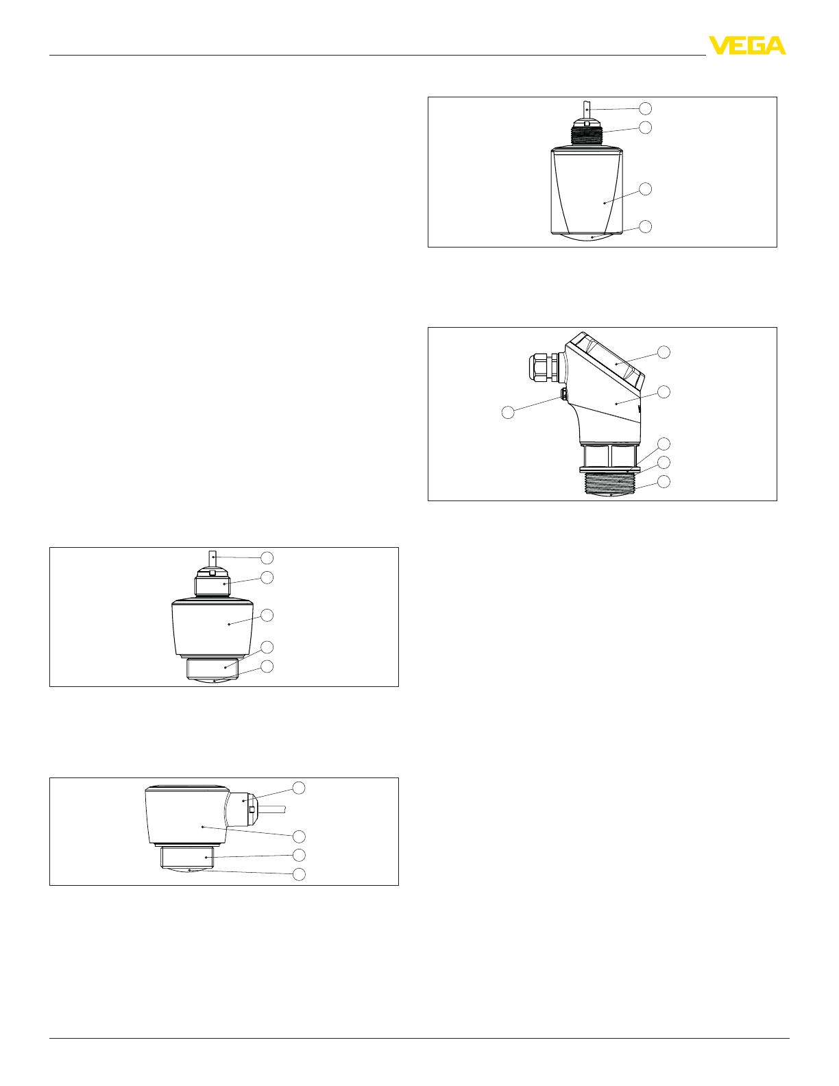
Conguration and housing protection classes
The radar sensors of series VEGAPULS 10, 20, 30 are available in dierent
designs, housing protection classes and connection techniques. The follow-
ing illustrations show typical examples.
3
4
5
1
2
Fig. 2: VEGAPULS C 11 with direct cable outlet in protection rating IP66/IP68 (3 bar)
1 Radar antenna
2 Processtting
3 Electronics housing
4 Mounting thread
5 Connection cable
1
2
3
Fig. 3: VEGAPULS C 22 with direct cable outlet for ceil mounting in protection rating
IP66/IP68 (3 bar)
1 Radar antenna
2 Processtting
3 Electronics housing
4 Cable outlet
3
4
1
2
Fig. 4: VEGAPULS C 23 with direct cable outlet in protection rating IP66/IP68 (3 bar)
1 Radar antenna
2 Electronics housing
3 Mounting thread
4 Connection cable
4
6
5
1
2
3
Fig. 5: VEGAPULS 31 in protection class IP66/IP67
1 Radar antenna
2 Processtting
3 Process seal
4 Electronics housing
5 Display and adjustment unit
6 Ventilation/pressure compensation


